Voltage Protection Relays: Types, Functions, Applications and Selection Guide for 33 kV and 11 kV Systems
- A voltage protection relays monitors electrical voltage and responds to abnormal conditions. When it detects overvoltage, undervoltage, residual overvoltage, three-phase voltage unbalance or phase loss, the relay evaluates the measured values against its configured settings and operating delays. Depending on the protection scheme, it can issue an alarm, trip command or control signal.
- Voltage protection relays are widely used in 33 kV and 11 kV substations, power plants, industrial distribution systems, motor switchgear, and solar photovoltaic (PV) and wind power grid connection projects.
- Voltage protection functions can be provided by a dedicated relay or integrated into a feeder protection relay, motor protection relay, generator protection relay, grid connection protection relay or automatic load shedding device.
1. What Is a Voltage Protection Relay?
- A voltage protection relay is a protective device that detects abnormal operating conditions by monitoring electrical voltage.
- In 33 kV and 11 kV systems, it normally receives secondary voltage signals from a voltage transformer (VT). The relay continuously compares the measured voltage with configured settings.
When an abnormal condition satisfies the applicable operating criteria for the specified time, the relay can:
- Issue an alarm;
- Send a trip command to a circuit breaker;
- Initiate automatic bus transfer logic;
- Initiate undervoltage load shedding;
- Report abnormal conditions to a monitoring system.
The actual response depends on the protection scheme, output wiring and relay configuration.
Basic Operating Process
- Voltage acquisition: The relay receives phase-to-neutral voltage, phase-to-phase voltage, residual voltage or other required voltage signals.
- Measurement and comparison: It compares the measured quantities with the configured voltage settings.
- Time delay: It checks whether the abnormal condition persists for the specified operating delay.
- Protection or control action: It issues an alarm, trip command or control signal and records the event, as supported by the device.
2. Main Types of Voltage Protection Relays
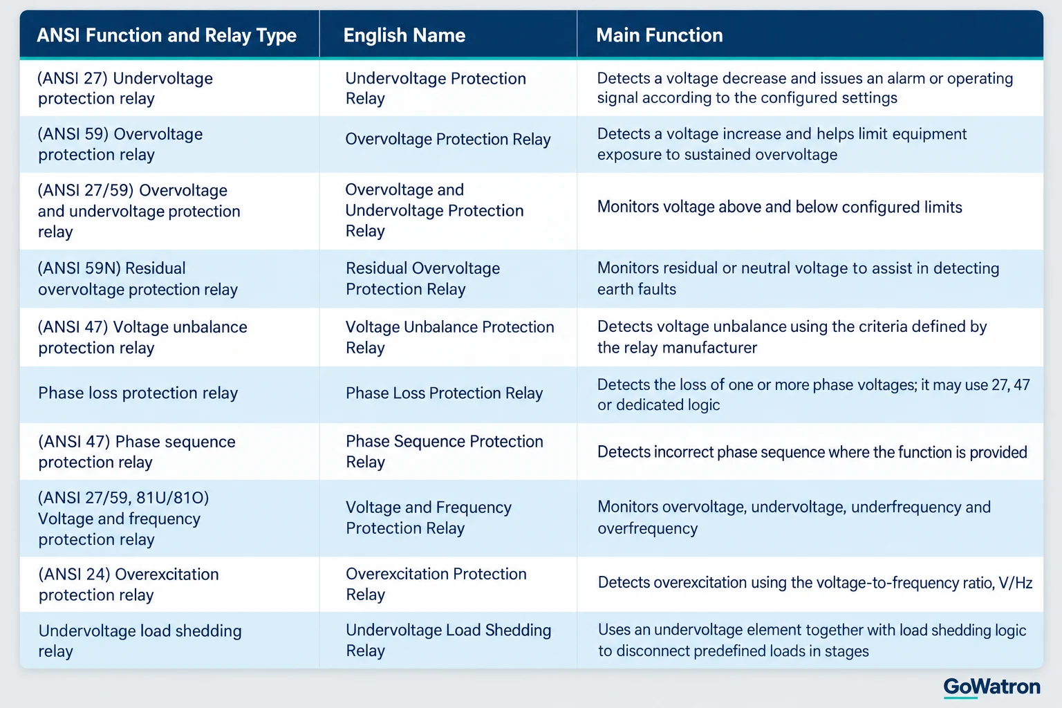
- Function names and ANSI suffixes may vary between manufacturers. The applicable device manual and protection logic should be checked for the selected relay.
- The (ANSI 47) designation may be used for voltage unbalance or phase-sequence-related functions, depending on the relay implementation. The availability of voltage unbalance protection does not by itself confirm that a separate phase sequence protection function is provided.
3. Functions of Voltage Protection Relays
3.1 (ANSI 27) Undervoltage Protection Relay
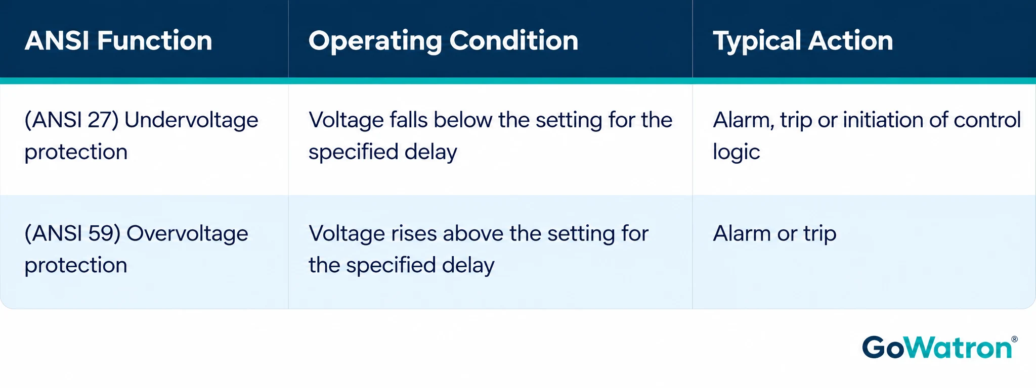
- An undervoltage protection relay detects a reduction in system voltage. When the measured voltage falls below a configured setting for the specified time, the relay issues the associated output signal.
- Undervoltage may result from an upstream supply failure, a system short circuit, insufficient supply capacity or a power supply transfer.
Typical applications include:
- Distribution feeders: Monitoring feeder voltage.
- Busbars: Detecting busbar loss of voltage and participating in automatic bus transfer logic.
- Motors: Initiating shutdown or participating in restart control according to process requirements.
- Generators and grid connection points: Detecting voltage abnormalities and operating according to the protection scheme.
- Undervoltage load shedding: Disconnecting predefined loads when the configured shedding criteria are satisfied.
For example, if the busbar voltage remains below its pickup setting for longer than the configured delay, the relay may issue an alarm or initiate a control action.
Undervoltage does not always require an immediate trip. Temporary voltage dips, equipment operating requirements and coordination with other protection devices must be considered.
3.2 (ANSI 59) Overvoltage Protection Relay
An overvoltage protection relay detects voltage above a configured limit.
When the voltage exceeds the pickup setting for the specified time, the relay can issue an alarm or trip command. This helps limit the exposure of generators, transformers, capacitor banks and other equipment to sustained overvoltage.
Typical applications include:
- Generator terminal voltage monitoring;
- Substation busbar voltage monitoring;
- Capacitor bank voltage protection;
- Solar PV and wind power grid connection protection;
- Industrial distribution system voltage monitoring.
Some relays provide multiple protection stages. For example, one stage may initiate an alarm and another may issue a trip command. The available stages and operating actions depend on the device configuration.
3.3 (ANSI 27/59) Overvoltage and Undervoltage Protection Relay
An overvoltage and undervoltage protection relay combines both functions in one device.
This type of relay is suitable where both upper and lower voltage limits must be monitored, including generator, distribution feeder, industrial load and renewable energy applications.
Voltage settings should be determined with reference to the normal operating range, equipment withstand capability, protection coordination and applicable grid connection requirements.
3.4 (ANSI 59N) Residual Overvoltage Protection Relay
- A residual overvoltage protection relay monitors residual voltage or neutral voltage for abnormal conditions associated with earth faults.
- When a single-phase-to-earth fault occurs, the measured residual voltage or neutral displacement voltage may increase. The relay compares the measured quantity with its configured pickup setting and operating delay, then issues an alarm or trip signal according to the protection scheme.
- Residual overvoltage protection is also described as neutral voltage displacement protection in some applications and manufacturer documentation.
Typical applications include:
- Earth-fault monitoring in unearthed neutral systems;
- Earth-fault monitoring in systems earthed through an arc-suppression coil;
- Generator stator earth-fault protection schemes;
- Earth-fault-related voltage monitoring on busbars and feeders.
The relay may receive the relevant voltage from an open-delta VT connection, a neutral voltage input or a calculated value derived from phase voltages. The measured quantity, VT connection, ratio and relay scaling must be confirmed for the selected scheme.
Residual overvoltage can indicate an earth-fault-related voltage abnormality, but (ANSI 59N) residual overvoltage protection alone generally cannot identify which feeder has the fault. Feeder selection may require residual current, directional elements or another earth-fault location method.
3.5 (ANSI 47) Three-Phase Voltage Unbalance Protection Relay
A voltage unbalance protection relay monitors the balance of the three-phase voltage supply.
Voltage unbalance can produce unbalanced motor currents, increase motor temperature and affect equipment operation. Monitoring voltage unbalance can therefore help identify abnormal supply conditions affecting motors and other three-phase loads.
Typical applications include:
- Three-phase motor protection;
- Industrial distribution systems;
- Motor control centres;
- Three-phase supply voltage monitoring.
Voltage unbalance protection and negative-sequence current protection monitor different quantities. Voltage unbalance protection assesses the supply voltage, while negative-sequence current protection monitors negative-sequence current.
The (ANSI 47) designation and the operating criteria should be checked against the selected relay’s documentation. A relay providing voltage unbalance protection does not necessarily provide a separate phase sequence protection function.
3.6 Phase Loss Protection Relay
- A phase loss protection relay detects the loss of one or more phase voltages in a three-phase supply.
- Phase loss may be caused by a blown fuse, a disconnected wire, a failed contact or an upstream supply abnormality. For a running three-phase motor, phase loss can result in abnormal current and overheating.
- When phase loss is detected, the relay can issue an alarm or trip command according to its configuration.
- Phase loss detection may use (ANSI 27) undervoltage elements, (ANSI 47) voltage unbalance elements or dedicated logic. The detection criteria, operating delay and response to VT circuit failure should be checked in the device manual.
3.7 (ANSI 47) Phase Sequence Protection Relay
- A phase sequence protection relay checks whether the three-phase supply has the required phase sequence.
- For motors, fans and pumps, an incorrect phase sequence can cause rotation in the wrong direction. Phase sequence protection can detect an incorrect sequence before starting or during operation and issue an alarm or blocking signal according to the control scheme.
Typical applications include:
- Motor control panels;
- Pumping and fan systems;
- Three-phase electrical equipment;
- Temporary supplies or installations where supply wiring may be changed.
The ANSI designation and detection logic should be checked against the selected device’s documentation.
3.8 Voltage and Frequency Protection Relay
A voltage and frequency protection relay monitors both system voltage and frequency. Common functions include:
- (ANSI 27) Undervoltage protection;
- (ANSI 59) Overvoltage protection;
- (ANSI 81U) Underfrequency protection;
- (ANSI 81O) Overfrequency protection.
These relays are commonly used for generators, industrial captive power plants, distributed generation and renewable energy grid connections.
Depending on the model, a device may also provide rate-of-change-of-frequency, rate-of-change-of-voltage or automatic load shedding functions.
3.9 (ANSI 24) Overexcitation Protection Relay
- Overexcitation protection generally uses the voltage-to-frequency ratio, V/Hz, to determine whether a generator or transformer is operating under an overexcitation condition.
- When voltage is too high or frequency is too low, V/Hz may increase, causing magnetic flux density to exceed the equipment’s intended operating range. The protection can issue an alarm or trip command according to its settings and operating characteristic.
Typical applications include:
- Generator protection;
- Generator-transformer unit protection;
- Transformer overexcitation protection.
3.10 Undervoltage Load Shedding Relay
- An undervoltage load shedding relay disconnects selected loads according to a predefined scheme when voltage remains low and the configured operating conditions are satisfied.
- The scheme uses an (ANSI 27) undervoltage element together with load shedding logic. Depending on the device, this logic may include multiple stages, operating delays, blocking conditions and configurable trip output assignments.
The objectives include:
- Reducing system loading;
- Supporting voltage recovery where appropriate;
- Reducing the risk of further system instability;
- Preserving the supply to priority loads where possible.
A load shedding scheme requires more than a voltage threshold. Its design should also consider system stability, load criticality, short-circuit fault blocking and voltage recovery conditions.
4. Applications of Voltage Protection Relays
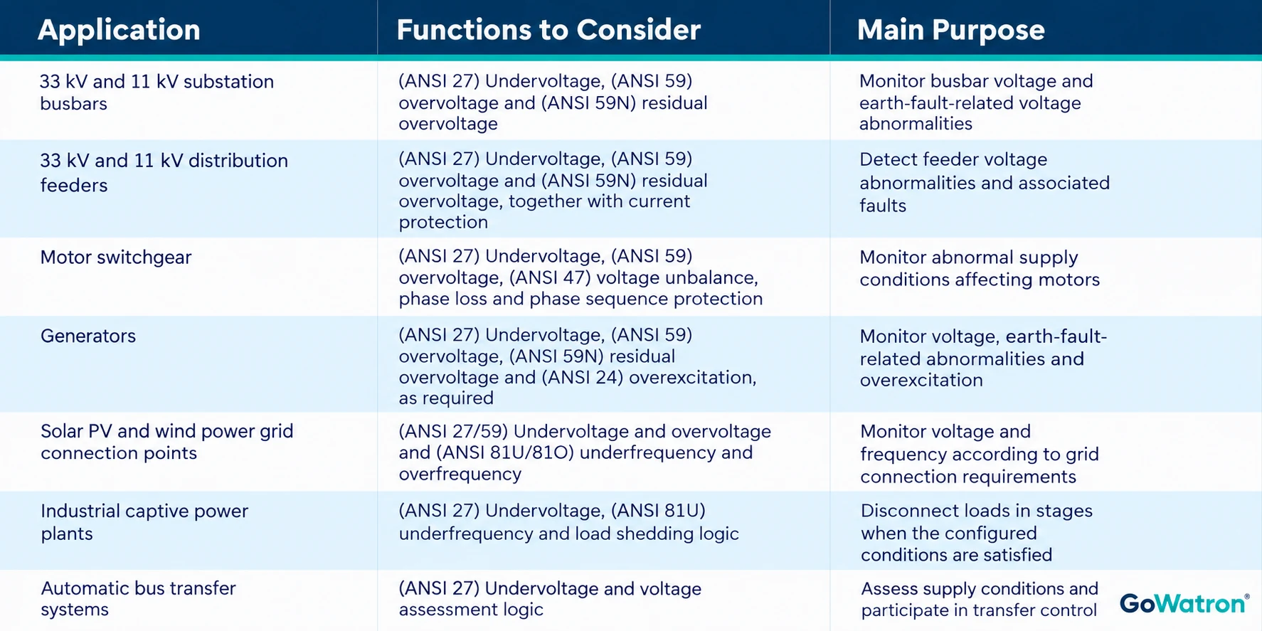
The choice of functions and whether they initiate an alarm or trip depend on the system configuration and operating requirements.
5. Voltage Protection and VT Circuit Supervision
Voltage protection depends on a reliable voltage input. In systems using voltage transformers, the condition of the VT secondary circuit is therefore also significant.
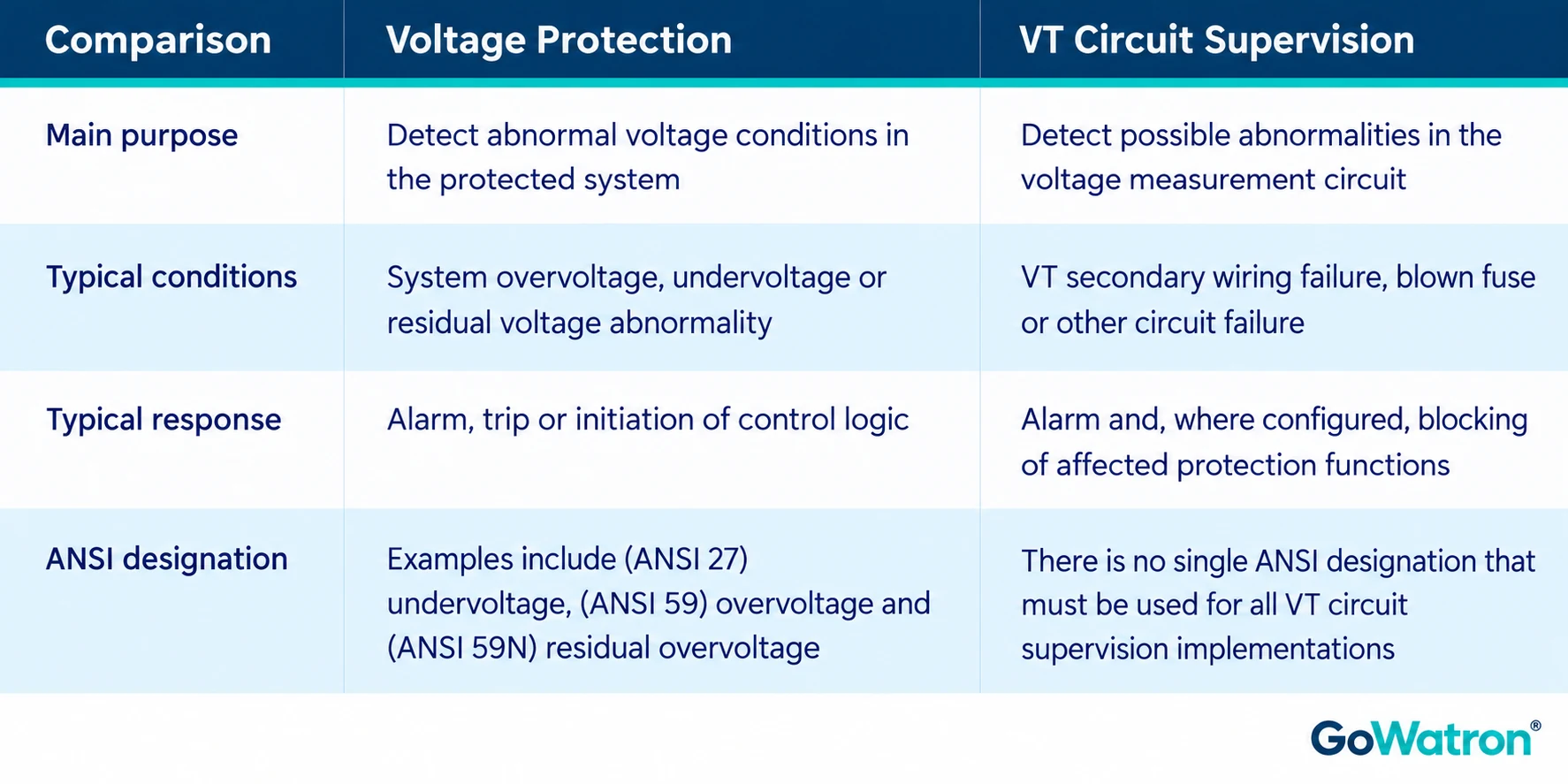
For example, a VT secondary circuit failure can cause the relay’s measured voltage to decrease even though the primary system voltage remains normal. Without suitable VT circuit supervision and blocking logic, some voltage-dependent functions could respond incorrectly.
When selecting a relay, check:
- Whether VT circuit failure supervision is available;
- Which protection functions are blocked when a VT circuit failure is detected;
- Whether an alarm is issued;
- Whether the blocking and reset conditions meet the project requirements.
6. Recommended GoWatron Products with Voltage Protection Functions
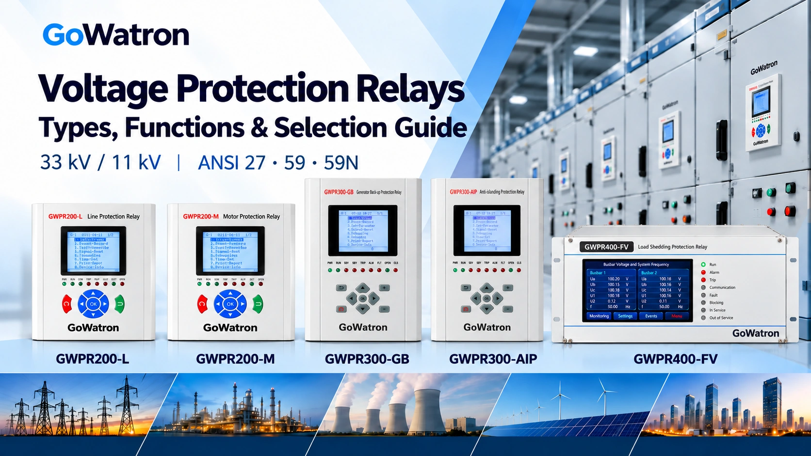
- GoWatron offers numerical protection relays with voltage-related functions for feeders, motors, generators, renewable energy grid connections and underfrequency or undervoltage load shedding.
- For 33 kV and 11 kV projects, selection should start with the protected equipment and the required protection scheme. A feeder application commonly requires current protection as well as voltage protection, while a renewable energy grid connection may also require frequency and anti-islanding functions.
6.1 Product Selection Table
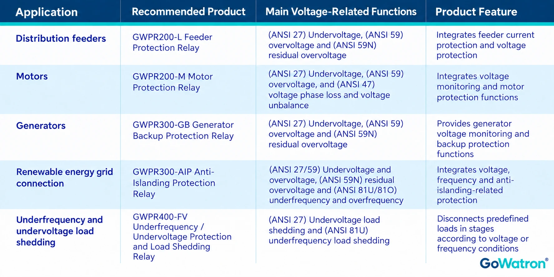
The table lists the principal functions relevant to this article; it is not a complete product function list. The configuration, input wiring and suitability must be confirmed against the selected product documentation and project requirements.
6.2 33 kV and 11 kV Feeder Voltage Protection: GWPR200-L
GWPR200-L Feeder Protection Relay
The GWPR200-L Feeder Protection Relay is suitable for distribution applications requiring both feeder current protection and voltage protection.
The device integrates feeder protection, measurement, control, event recording and communication functions. Its principal voltage-related functions include:
- (ANSI 27) Undervoltage protection;
- (ANSI 59) Overvoltage protection;
- (ANSI 59N) Residual overvoltage protection.
For 33 kV and 11 kV distribution feeder applications, the GWPR200-L can be used with the corresponding current transformers (CTs), VTs and circuit breaker to form a feeder protection scheme.
Recommended applications:
- Substation incoming and outgoing feeder switchgear;
- Industrial distribution feeders;
- Medium-voltage cables and overhead lines;
- Distribution protection retrofit projects.
The relay is intended for distribution systems up to 35 kV with applicable neutral earthing arrangements. For solidly earthed systems, consult GoWatron before selection.
6.3 Motor Voltage Protection: GWPR200-M
GWPR200-M Motor Protection Relay
The GWPR200-M Motor Protection Relay is suitable for applications requiring voltage monitoring together with integrated motor protection.
Its principal voltage-related functions include:
- (ANSI 27) Undervoltage protection;
- (ANSI 59) Overvoltage protection;
- (ANSI 47) Voltage phase loss and voltage unbalance protection.
The device also integrates motor protection and electrical measurement functions. The available functions, operating logic and input configuration should be confirmed against the selected product documentation.
Recommended applications:
- Motor switchgear;
- Industrial pumps, fans and compressors;
- Motor control and protection systems;
- Motor protection retrofit projects.
6.4 Generator Voltage Protection: GWPR300-GB
GWPR300-GB Generator Backup Protection Relay
The GWPR300-GB Generator Backup Protection Relay is designed for generator backup protection and monitors voltage, current and other operating conditions.
Its principal voltage-related functions include:
- (ANSI 59) Overvoltage protection;
- (ANSI 27) Undervoltage protection;
- (ANSI 59N) Residual overvoltage protection.
For generator applications, the voltage protection configuration should be designed with reference to the generator neutral earthing arrangement, VT wiring and required protection coverage.
Recommended applications:
- Power plant generator protection;
- Industrial captive power plants;
- Generator protection panels;
- Generator backup protection retrofit projects.
6.5 Renewable Energy Grid Connection Voltage Protection: GWPR300-AIP
GWPR300-AIP Anti-Islanding Protection Relay
The GWPR300-AIP Anti-Islanding Protection Relay is suitable for distributed generation and renewable energy grid connection projects. It monitors voltage, frequency and other electrical quantities at the grid connection point.
Its principal voltage and frequency functions include:
- (ANSI 59) Overvoltage protection;
- (ANSI 27) Undervoltage protection;
- (ANSI 59N) Residual overvoltage protection;
- (ANSI 81O) Overfrequency protection;
- (ANSI 81U) Underfrequency protection;
- (ANSI 81df) Rate-of-change-of-frequency protection, df/dt.
The GWPR300-AIP can be used in grid connection schemes requiring a combination of voltage, frequency and anti-islanding-related functions. Protection configuration, operating times and settings should comply with the requirements of the applicable grid operator.
Recommended applications:
- Solar PV power plant grid connection;
- Wind farm grid connection;
- Distributed generation systems;
- Renewable energy grid connection protection panels.
6.6 Underfrequency and Undervoltage Load Shedding: GWPR400-FV
GWPR400-FV Underfrequency / Undervoltage Protection and Load Shedding Relay
The GWPR400-FV Underfrequency / Undervoltage Protection and Load Shedding Relay is suitable for projects that require predefined loads to be disconnected in stages in response to frequency or voltage conditions.
Its main functions include:
- (ANSI 81U) Underfrequency load shedding: 8 stages;
- (ANSI 27) Undervoltage load shedding: 8 stages;
- Accelerated load shedding based on rate of change of frequency, df/dt;
- Accelerated load shedding based on rate of change of voltage, dU/dt;
- Voltage monitoring for two busbar sections;
- VT circuit failure supervision and associated blocking;
- Configurable load shedding stages and trip output assignments.
The relay provides 8 underfrequency load shedding stages and 8 undervoltage load shedding stages. Each function comprises 5 basic stages and 3 special stages.
Acceleration is initiated only when the configured acceleration criteria are satisfied and the applicable blocking conditions are inactive.
The load shedding scheme should be developed with reference to system stability studies, load criticality and the available interruptible load capacity.
Recommended applications:
- Industrial captive power plants;
- Islanded power systems;
- Power plants and substations;
- Renewable energy projects requiring automatic underfrequency and undervoltage load shedding.
7. How to Select a Voltage Protection Relay for a 33 kV or 11 kV System
7.1 Identify the Protected Equipment
First, identify the equipment or part of the system to be protected:
- Distribution feeder;
- Motor;
- Generator;
- Substation busbar;
- Renewable energy grid connection point;
- Power system requiring automatic load shedding.
If the project also requires overcurrent, earth-fault or motor protection, an integrated protection relay with voltage functions may be appropriate.
7.2 Identify the Required Protection Functions
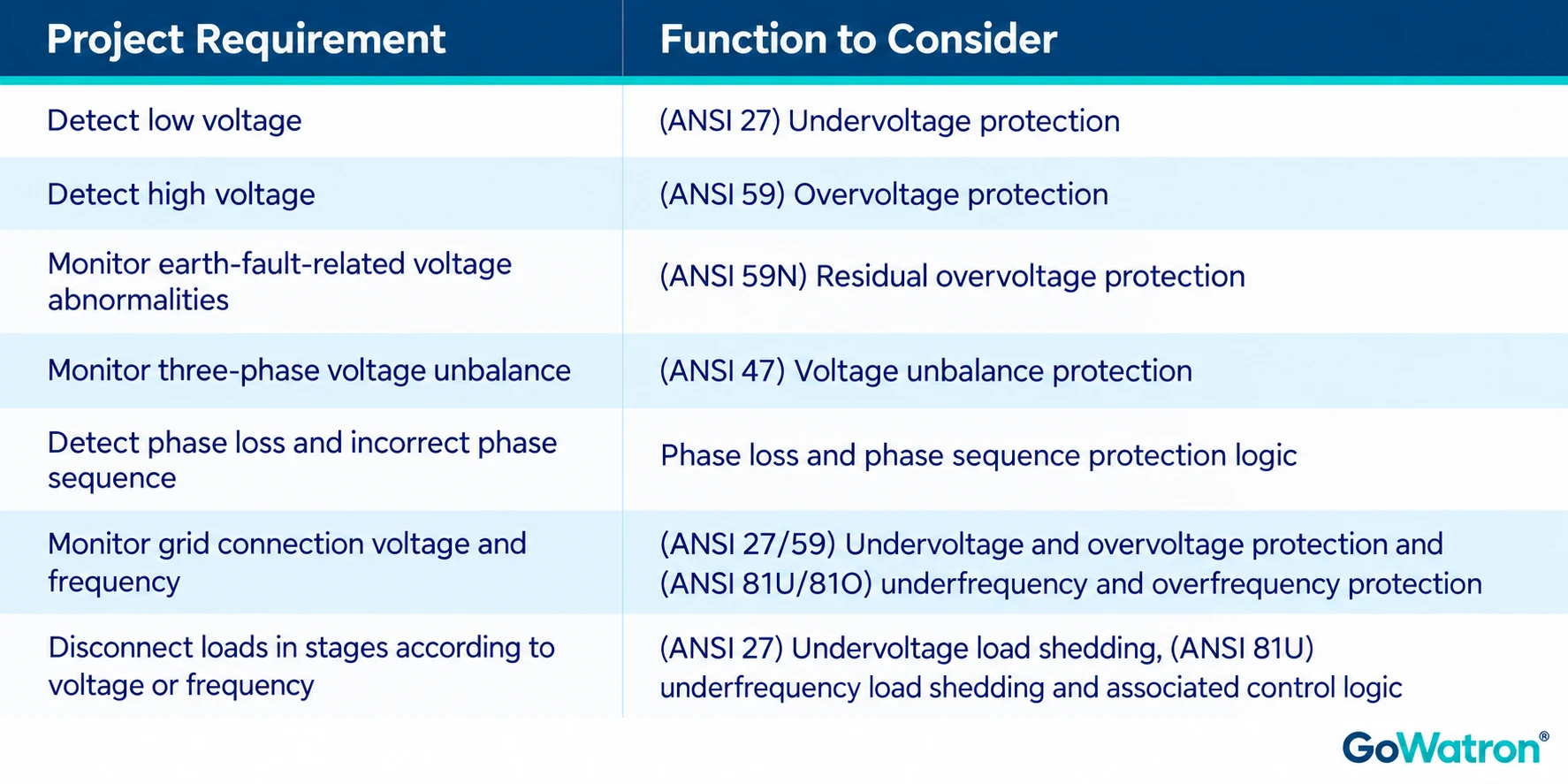
7.3 Confirm System Voltage and Input Arrangement
Confirm whether the nominal system voltage is 33 kV or 11 kV.
The relay normally receives secondary voltage signals from a VT. Check:
- VT primary and secondary rated voltages;
- VT ratio;
- Phase-to-neutral or phase-to-phase voltage connection;
- Whether a residual voltage input is required;
- Relay rated input and permissible input range.
The 33 kV or 11 kV primary system voltage is not the relay’s direct input voltage. Wiring must be designed according to the product specifications and the project’s electrical design.
7.4 Confirm Operating and Control Requirements
Determine whether the relay must:
- Issue an alarm only;
- Trip after a time delay;
- Initiate automatic bus transfer;
- Initiate undervoltage load shedding;
- Report status and events to a monitoring system.
Also confirm the required protection stages, operating delays, output contacts and coordination with other devices.
7.5 Confirm VT Circuit Supervision and Blocking Requirements
For schemes that use VT inputs, check:
- Whether VT circuit failure supervision is provided;
- Which functions must be blocked during a VT circuit failure;
- How the device reports the abnormal condition;
- The conditions for resetting the alarm and releasing the blocking.
7.6 Confirm Communication and Installation Requirements
Depending on the project, check:
- RS-485 or Ethernet interfaces;
- Required protocols, such as Modbus RTU, IEC 60870-5-103, IEC 60870-5-104 or IEC 61850;
- Flush mounting in switchgear or installation in a centralised protection panel;
- Required numbers of inputs and outputs;
- Time synchronisation and event recording requirements.
Standard and optional communication interfaces and protocols vary by model and must be confirmed before ordering.
8. Request Voltage Protection Relay Selection Support and a Quotation
If you need a voltage protection solution for a 33 kV or 11 kV system, GoWatron can assist with the selection of feeder protection, motor protection, generator protection, grid connection protection or underfrequency and undervoltage load shedding products.
To help us recommend a suitable model, please provide:
- Nominal system voltage and frequency;
- Protected equipment and system earthing arrangement;
- Required functions, such as (ANSI 27) undervoltage, (ANSI 59) overvoltage, (ANSI 59N) residual overvoltage or (ANSI 47) voltage unbalance protection;
- VT secondary rated voltage and connection arrangement;
- Alarm, trip and control requirements;
- Communication interface and protocol requirements;
- Expected quantity and project destination.
Contact GoWatron for voltage protection relay selection support and a quotation.


