3-Phase Motor Protection Relays: Selection Guide, ANSI Functions & Configuration
Document Type: Technical Articles
Document Published: 2026-10-21
Last Updated: 2026-10-27
1. Overview of 3-Phase Motor Protection Relays
- A 3-phase motor protection relay is a numerical protection device designed to monitor three-phase alternating-current (AC) motors and protect them against electrical faults, thermal overload, abnormal starting conditions and operational disturbances.
- Three-phase motors are widely used in power generation, petrochemical plants, mining operations, water treatment facilities, manufacturing plants and industrial power distribution systems. Depending on motor capacity, voltage level, starting characteristics and operating requirements, different protection functions and relay configurations may be necessary.
- Modern numerical motor protection relays typically provide thermal overload protection, instantaneous and time overcurrent protection, negative-sequence current protection, earth-fault overcurrent protection, undercurrent protection, excessive starting time protection and locked-rotor protection. More comprehensive protection schemes may also include motor differential protection, bearing temperature protection, fault recording and communication with supervisory control and data acquisition (SCADA) systems.
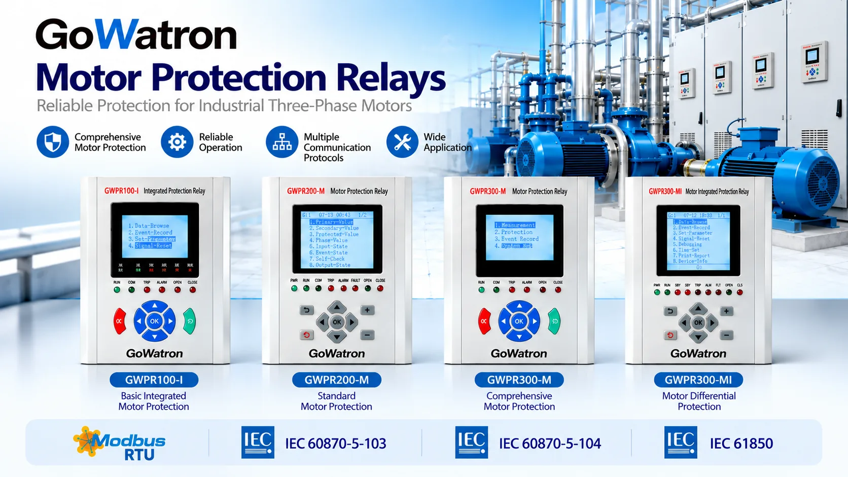
- The GoWatron GWPR Series Protection Relays offer different configurations for industrial motor protection, ranging from basic electrical protection to comprehensive motor protection and motor differential protection.
- Selecting a suitable 3-phase motor protection relay requires consideration of motor electrical parameters, starting characteristics, protection requirements, current transformer (CT) arrangements and automation system architecture.
2. How to Select a 3-Phase Motor Protection Relay
- Selecting a 3-phase motor protection relay involves more than matching the relay to the motor’s rated voltage or power.
- Motor starting current, permissible starting time, thermal withstand capability, CT characteristics, system earthing arrangement and required protection functions must also be considered.
2.1 Motor Electrical Parameters
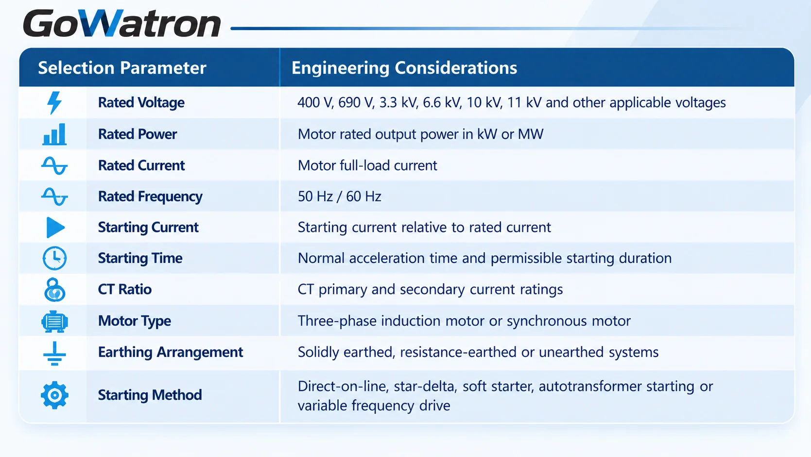
- Motor rated current, starting current and permissible starting time are particularly important when determining thermal overload, overcurrent, excessive starting time and locked-rotor protection settings.
- For example, a conventional 6.6 kV induction motor may require thermal overload, overcurrent, negative-sequence current, earth-fault overcurrent and undercurrent protection. A large 11 kV motor serving a critical industrial process may additionally require motor differential protection.
- Synchronous motors may require additional functions, such as loss-of-synchronism or excitation-related protection, depending on their design and operating requirements. These functions should be evaluated separately from the standard induction motor protection configuration.
2.2 Motor Starting Methods and Protection Requirements
Different starting methods produce different current and thermal characteristics.
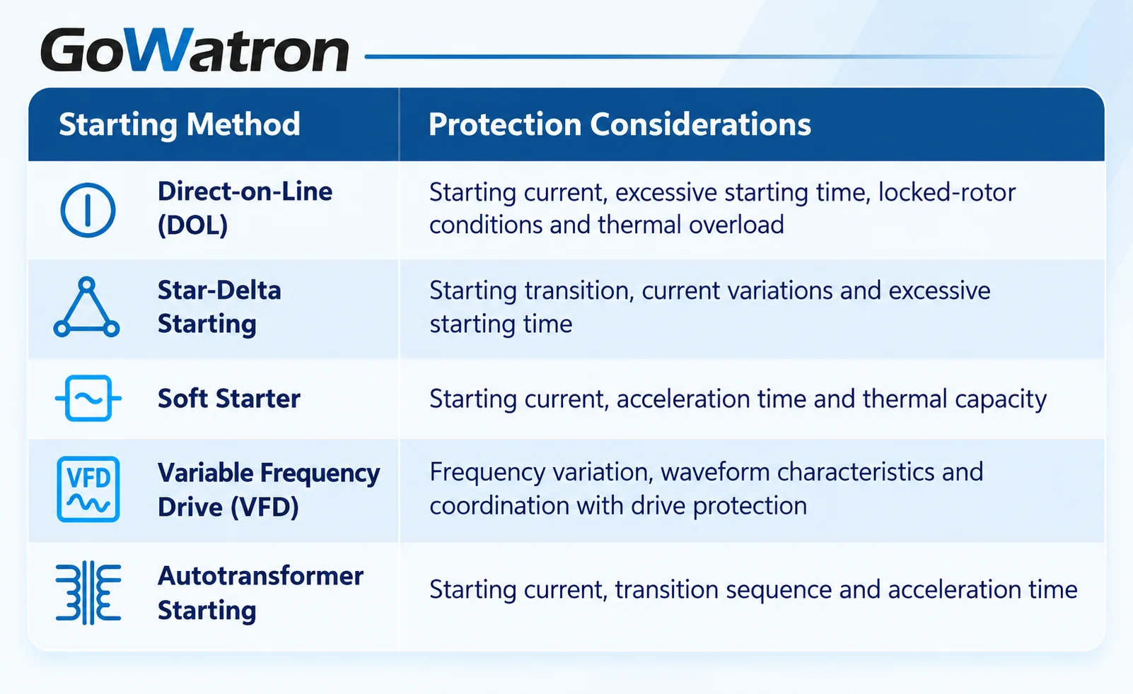
- For VFD applications, the protection relay’s measurement characteristics must be compatible with the installation point and applicable frequency range.
- A fixed-frequency protection relay should not be assumed suitable for direct connection to the VFD output without verifying its measurement compatibility over the applicable frequency range.
3. ANSI Protection Functions and GWPR Series Relay Selection
- The GoWatron GWPR series provides different protection configurations for three-phase AC motors, ranging from basic electrical protection to comprehensive motor protection and motor differential protection.
- The following ANSI protection function comparison helps engineers select a suitable GWPR protection relay according to motor operating conditions, required protection functions and system complexity. The functions are identified using ANSI device function designations.
3.1 GWPR Series Motor Protection Relays – ANSI Function Comparison
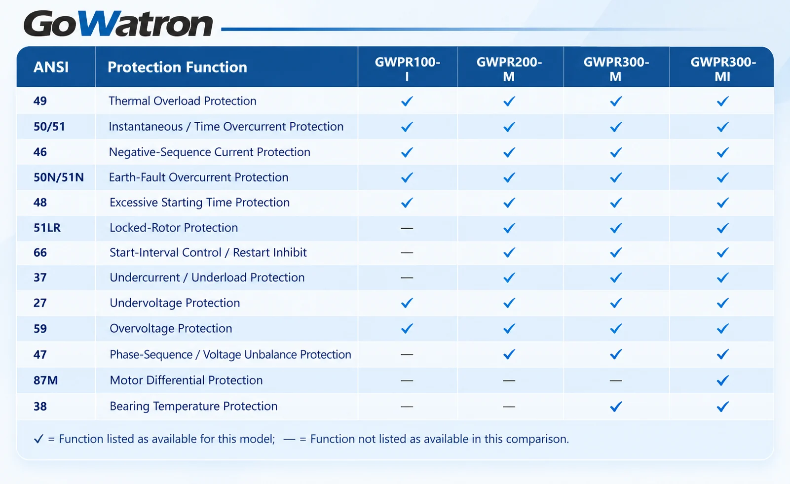
- Protection settings, measurement inputs and communication options should be verified against the applicable product specifications.
- In this article, Undercurrent / Underload Protection (ANSI 37) refers to the undercurrent protection element used to detect low-current or loss-of-load conditions. Its suitability for a particular process depends on the relationship between motor current and mechanical load.Protection settings, measurement inputs and communication options should be verified against the applicable product specifications.
3.2 GWPR Series Motor Protection Relay Selection
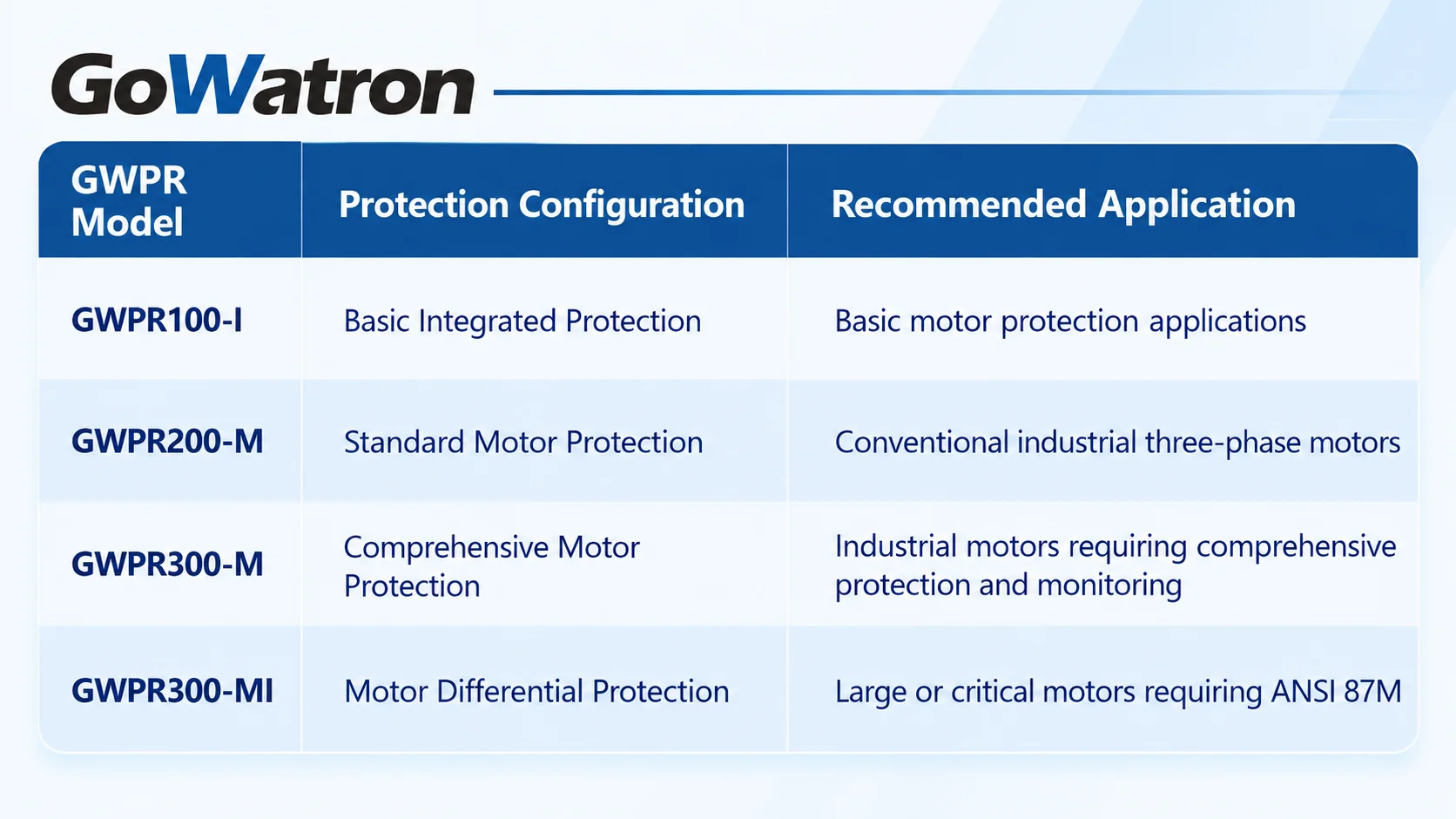 The GWPR100-I provides basic motor protection functions, including thermal overload, overcurrent, negative-sequence current, earth-fault overcurrent, excessive starting time, undervoltage and overvoltage protection.
- For conventional industrial motors, the GWPR200-M provides a dedicated motor protection configuration with additional functions such as locked-rotor protection, undercurrent protection, start-interval control / restart inhibit (ANSI 66) and phase-sequence / voltage unbalance protection.
- The GWPR300-M is suitable for more demanding industrial motor applications requiring comprehensive protection, monitoring and bearing temperature protection.
- For large or critical motors, the GWPR300-MI provides motor differential protection (ANSI 87M) in addition to conventional motor protection functions.
- In the model designations used here, the suffix -I denotes the integrated basic protection configuration, -M denotes the motor protection configuration, and -MI denotes the motor protection configuration with differential protection.
4. Working Principles of Main Motor Protection Functions
4.1 Thermal Overload Protection (ANSI 49)
- Thermal overload protection is one of the most important functions of a 3-phase motor protection relay.
- During normal operation, a motor generates heat due to electrical and mechanical losses. Excessive current, prolonged starting or repeated starting can cause the motor’s thermal condition to exceed its permissible limits.
- A numerical motor protection relay estimates motor heating using a thermal model based on measured current and configured motor characteristics. Depending on the relay design, the model may use current-squared heating characteristics and accumulated thermal capacity to estimate the motor’s thermal state.
- Protection settings should consider the motor’s rated current, thermal time constants, permissible starting time, heating characteristics and cooling characteristics.
- The GWPR series provides thermal overload protection across the four listed configurations, helping reduce the risk of damage caused by sustained overload and excessive thermal stress.
4.2 Instantaneous / Time Overcurrent Protection (ANSI 50/51)
- Overcurrent protection detects abnormal current conditions associated with short circuits and excessive current.
- ANSI 50 provides instantaneous overcurrent protection, while ANSI 51 provides time-delayed overcurrent protection.
- Since motor starting currents can be considerably higher than rated operating current, overcurrent protection must be coordinated with the motor’s normal starting characteristics.
- The GWPR series provides overcurrent protection functions that can be coordinated with upstream protective devices to achieve appropriate fault clearance and selectivity.
4.3 Negative-Sequence Current Protection (ANSI 46)
- Negative-sequence current protection detects unbalanced three-phase current conditions caused by phase loss, unequal phase impedances or supply disturbances.
- Negative-sequence current produces additional rotor heating, potentially damaging the motor during prolonged abnormal operation.
- The protection pickup and operating delay should be coordinated with the motor’s permissible negative-sequence withstand capability.
- ANSI 46 is based on current unbalance or negative-sequence current, whereas ANSI 47 is associated with voltage phase-sequence or voltage unbalance conditions. These protection functions should be distinguished when selecting and configuring the relay.
4.4 Earth-Fault Overcurrent Protection (ANSI 50N/51N)
- Earth-fault overcurrent protection detects faults involving motor windings or associated conductors and earth.
- Residual current can be measured by summing the three phase CT currents or using a dedicated core-balance current transformer (CBCT), also known as a zero-sequence CT.
- The appropriate pickup setting depends on the system earthing arrangement, available earth-fault current and required sensitivity.
- For GWPR series applications, the residual-current measurement arrangement and protection settings should be selected according to the motor feeder design.
4.5 Excessive Starting Time Protection (ANSI 48)
- Excessive starting time protection detects motor starting conditions in which the motor fails to complete acceleration within the permitted time.
- Prolonged starting may result from mechanical overload, low supply voltage, high driven-load inertia or other abnormal conditions.
- The starting-time setting should be based on the motor’s normal acceleration characteristics and thermal withstand capability.
4.6 Locked-Rotor Protection (ANSI 51LR)
- Locked-rotor protection detects conditions in which the motor rotor cannot accelerate normally or becomes stalled during operation.
- A locked-rotor condition may cause high current and rapid thermal stress.
- The protection characteristic must be coordinated with the motor’s permissible locked-rotor withstand time, particularly for heavy-duty industrial motors.
- The operating logic should distinguish starting conditions from running conditions where required by the motor protection scheme.
4.7 Start-Interval Control / Restart Inhibit (ANSI 66)
- Repeated motor starting can cause significant thermal stress.
- Start-interval control / restart inhibit prevents excessive starting frequency and restricts restarting when the required conditions have not been satisfied.
- This function is particularly important for motors used in applications involving frequent starting and stopping.
- Settings should consider the motor’s permissible starting frequency, minimum interval between starts and thermal condition.
4.8 Undercurrent / Underload Protection (ANSI 37)
- Undercurrent protection detects a reduction in motor operating current below a configured threshold.
- This condition may indicate loss of mechanical load, dry running of a pump, belt failure, loss of material flow or other abnormal operating conditions.
- The GWPR200-M, GWPR300-M and GWPR300-MI provide undercurrent protection capabilities for industrial motor applications.
- The undercurrent pickup should be set below the minimum expected current during normal loaded operation, with an appropriate delay to avoid unnecessary operation during starting, stopping or temporary load fluctuations.
- Undercurrent protection should not be regarded as a universal substitute for dedicated dry-running protection or process instrumentation, particularly where motor current changes are small.
4.9 Undervoltage Protection (ANSI 27)
- Undervoltage protection detects supply voltage falling below a configured threshold.
- Low voltage may reduce motor starting torque, increase acceleration time and cause excessive current under certain operating conditions.
- Undervoltage settings should consider motor operating limits, system voltage variations and coordination with the motor control scheme.
4.10 Overvoltage Protection (ANSI 59)
- Overvoltage protection detects supply voltage exceeding a configured threshold.
- Excessive voltage may increase insulation stress and magnetic losses.
- Overvoltage protection settings should be coordinated with permissible motor operating voltage and expected system conditions.
4.11 Phase-Sequence / Voltage Unbalance Protection (ANSI 47)
- Phase-sequence / voltage unbalance protection monitors abnormal three-phase voltage conditions, including incorrect phase sequence and voltage unbalance.
- These conditions can cause abnormal motor operation, increased heating, reduced torque and unstable operating conditions.
- ANSI 47 is a voltage-based protection function and should be distinguished from negative-sequence current protection (ANSI 46).
- The specific measuring principle depends on the relay design. Where both ANSI 46 and ANSI 47 are available, their settings and operating logic should be coordinated to provide appropriate protection against phase-related abnormalities.
4.12 Motor Differential Protection (ANSI 87M)
- Motor differential protection provides selective protection for internal faults within the defined differential protection zone.
- The operating principle compares currents entering and leaving the protected zone.
- Under normal operating conditions or external faults, the differential current, after applying the necessary CT ratio compensation and phase compensation (where required), should remain below the operating threshold.
- An internal fault produces an imbalance between the currents entering and leaving the protected zone. When the differential current exceeds the applicable operating threshold and satisfies the relay’s restraint characteristics, the protection initiates tripping.
- Differential protection is particularly relevant for large, expensive or critical motors where rapid and selective internal fault clearance is required.
- Within the GWPR series, the GWPR300-MI provides motor differential protection in combination with conventional motor protection functions.
4.13 Bearing Temperature Protection (ANSI 38)
- Bearing temperature protection monitors abnormal temperature conditions associated with motor bearings.
- Excessive bearing temperature may result from lubrication problems, mechanical wear, misalignment or other abnormal operating conditions.
- Depending on the measurement arrangement, the protection system may use bearing temperature sensors or external monitoring signals to initiate alarms or trips.
- The GWPR300-M and GWPR300-MI provide bearing temperature protection, as shown in the function comparison table in Section 3.1.
- Bearing temperature protection complements electrical thermal overload protection (ANSI 49) but does not replace it.
5. Motor Protection Configuration by Application
- The appropriate protection configuration depends on the motor’s operating characteristics and the consequences of a protection failure.5. Motor Protection Configuration by Application
- The appropriate protection configuration depends on the motor’s operating characteristics and the consequences of a protection failure.
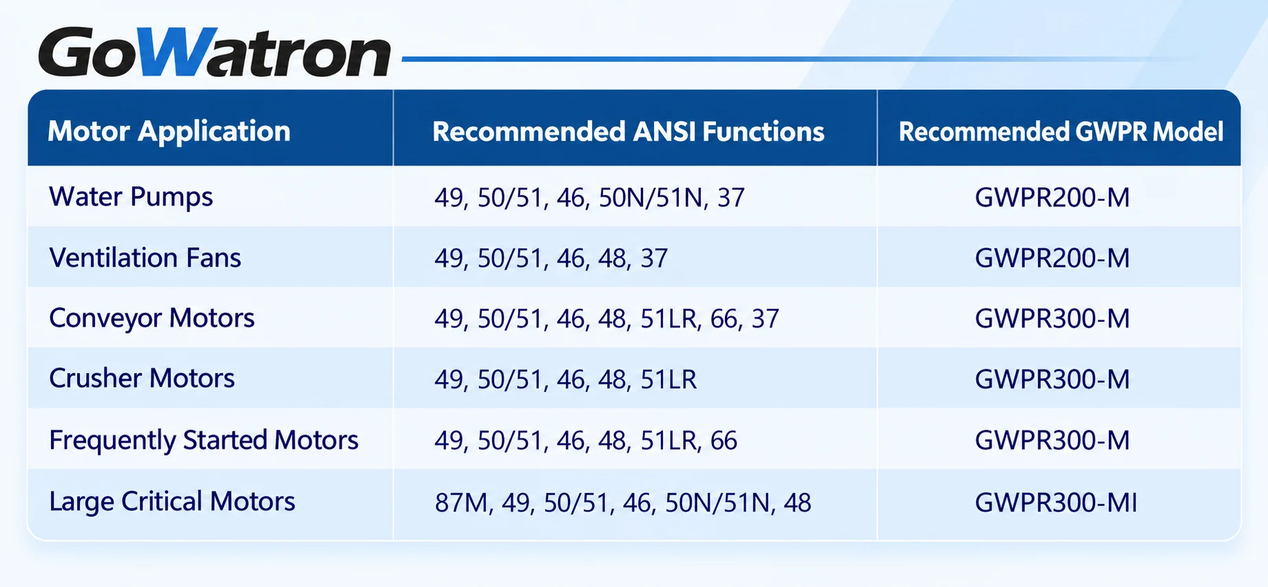
- These configurations provide general engineering guidance. Additional functions may be necessary depending on motor design, system earthing arrangement and operating requirements.
- For water pumps and conveyors, undercurrent protection (ANSI 37) can provide additional supervision of abnormal load conditions. Positive-displacement pumps and deep-well pumps may require additional starting supervision or locked-rotor protection (ANSI 51LR).
- High-inertia fans may also require locked-rotor protection (ANSI 51LR) to detect abnormal starting or stalling conditions.
- For large and critical motors, bearing temperature protection (ANSI 38) and voltage protection (ANSI 27/59) should also be considered, together with motor differential protection (ANSI 87M).
6. Communication and SCADA Integration
- Modern motor protection relays are increasingly integrated into industrial automation systems and electrical monitoring networks.
- In addition to fault protection, numerical relays may provide electrical measurements, alarms, event records, operating status and remote control capabilities.
- Depending on the GWPR series configuration, communication options may include:
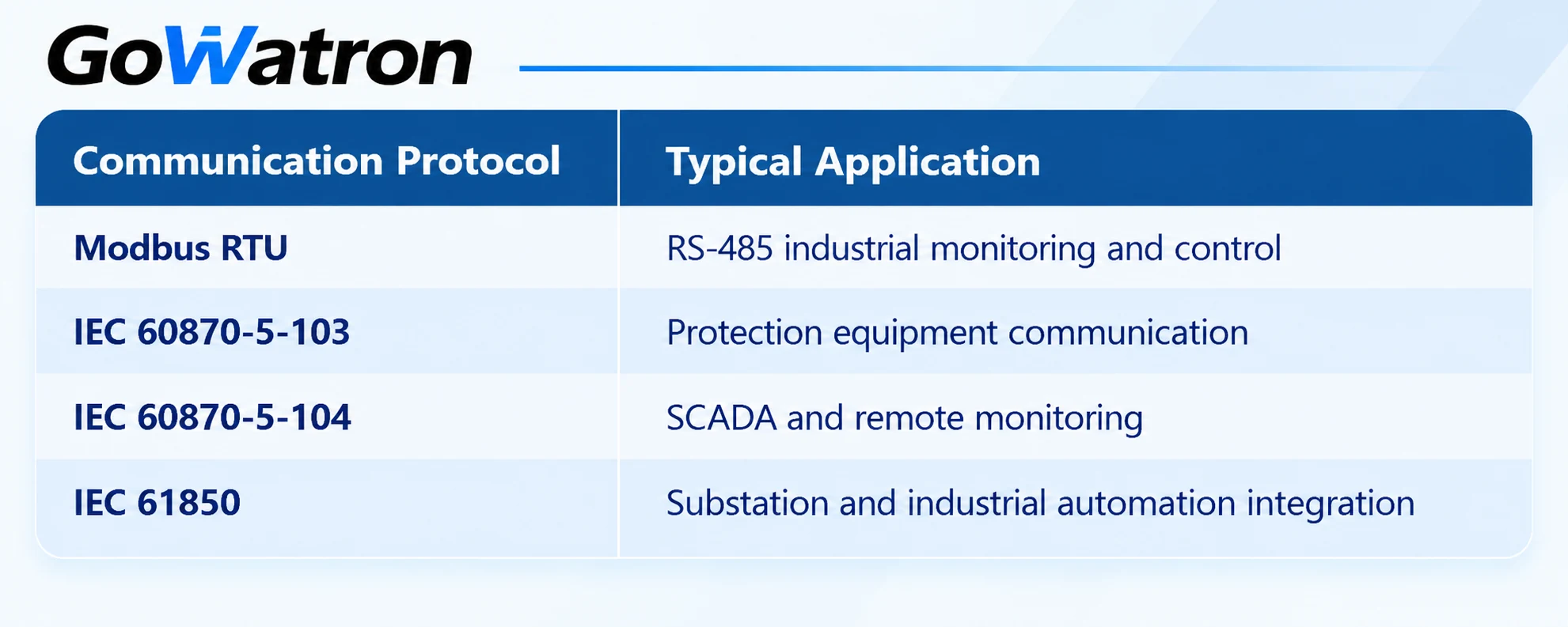
- The availability of each protocol depends on the selected relay hardware, firmware and communication configuration. IEC 61850 may be provided as an optional feature where supported.
- Through suitable communication interfaces, GWPR series protection relays can be integrated into industrial SCADA systems for centralised motor monitoring, fault indication and operational supervision.
7. Motor Protection Relay Setting Considerations
- Correct protection settings are essential for reliable motor operation.
7.1 Rated Current and CT Configuration
- The motor protection relay’s rated current settings should be coordinated with the motor nameplate current and the installed CT ratio.
- CT accuracy and saturation performance should also be considered, particularly during motor starting and short-circuit conditions.
7.2 Thermal Overload Settings
- Thermal overload settings should reflect the motor’s permissible heating characteristics.
- The thermal model should account for motor rated current, starting conditions, heating and cooling characteristics and permissible thermal capacity.
7.3 Overcurrent Coordination
- Overcurrent protection must distinguish between normal motor starting current and genuine fault current.
- Instantaneous and time-delayed elements should be coordinated with motor starting characteristics and upstream protection devices.
7.4 Starting and Locked-Rotor Settings
- Excessive starting time and locked-rotor protection settings should be based on the motor’s acceleration characteristics and permissible thermal withstand time.
- For heavy-duty motors, additional consideration should be given to high-inertia loads and prolonged acceleration.
7.5 Undercurrent Settings
- Undercurrent protection should be configured according to the minimum expected operating current under normal load conditions.
- The pickup threshold and operating delay should avoid unnecessary tripping during temporary load reductions, starting or stopping.
7.6 Earth-Fault Settings
- Earth-fault overcurrent protection settings should be selected according to the system earthing arrangement, available earth-fault current and required sensitivity.
- Where a dedicated CBCT is used, its ratio and measurement characteristics should be considered.
7.7 Motor Differential Protection Settings
- For motors equipped with motor differential protection (ANSI 87M), settings should account for CT ratios, polarity, protection-zone boundaries and possible CT saturation during external faults.
- Differential pickup and restraint characteristics should be coordinated with the motor protection relay manufacturer’s recommendations and the protection scheme design.
7.8 Bearing Temperature Settings
- Bearing temperature protection settings should be coordinated with the motor manufacturer’s recommended bearing temperature limits and the installed sensor characteristics.
- Alarm and trip thresholds should be selected according to motor operating conditions and maintenance requirements.
8. Conclusion
- Selecting a suitable 3-phase motor protection relay requires a comprehensive assessment of motor electrical parameters, starting characteristics, thermal limits, protection requirements and communication needs.
- For conventional industrial motors, thermal overload, overcurrent, negative-sequence current, earth-fault overcurrent, undercurrent and voltage protection (ANSI 27/59) form an important part of the protection scheme.
- Heavy-duty applications may require additional excessive starting time protection, locked-rotor protection and start-interval control / restart inhibit, while large or critical motors may benefit from motor differential protection.
- The GoWatron GWPR Series Protection Relays provide different protection, measurement and communication configurations for industrial motor applications.
- By selecting the appropriate protection relay and coordinating protection settings with actual motor operating characteristics, engineers can improve protection reliability, reduce equipment damage risks and minimise unplanned downtime.


