Motor Differential Protection (ANSI 87M): Working Principle, Purpose and Setting Calculation
- Motor differential protection (ANSI 87M) is the main protection for large high-voltage motors, used to rapidly clear internal phase-to-phase short circuits. This article explains in detail the working principle, protection functions, setting calculation methods and typical settings of 87M, helping electrical engineers quickly master the key setting points.
- Applicability Note: According to GB/T 50062-2008 Code for Design of Relaying Protection and Automatic Device of Electric Power Installations, for motors of 3 kV and above, instantaneous overcurrent protection is generally preferred for motors below 2 MW; for motors of 2 MW and above, or motors below 2 MW whose instantaneous overcurrent protection sensitivity does not meet requirements, longitudinal differential protection shall be installed, with instantaneous tripping. In a complete motor protection scheme, 87M is usually also coordinated with overcurrent, negative-sequence, earth-fault, thermal overload and other protection functions to form a complete scheme combining main protection with other fault/abnormal operating protections. In actual engineering practice, some important high-voltage motors below 2 MW with high requirements for production continuity (such as critical pumps/compressors in the petrochemical and metallurgical industries) may also be equipped with differential protection according to project protection configuration requirements.
1. Working Principle of Motor Differential Protection (87M)
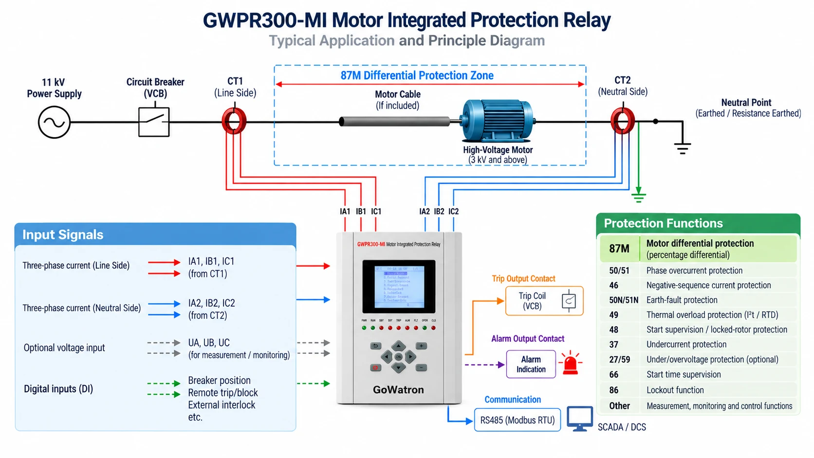
- The core principle of motor differential protection is Kirchhoff’s Current Law: during normal operation and external faults, the current flowing into and out of the differential protection zone remains theoretically balanced, and the differential current is close to zero; when a phase-to-phase short circuit occurs inside the protection zone, the current balance is broken, the differential current increases significantly, and when it exceeds the operating boundary, the protection trips.
- Modern numerical protection relays for 87M generally adopt the percentage differential protection characteristic, forming an operating boundary based on the relationship between the differential current and the restraint current, thereby achieving both internal fault sensitivity and external fault stability.
1.1 Definition of Differential Current and Restraint Current
Polarity Convention: For the polarity convention used in this article, the CT polarities are defined so that current flowing into the protected motor zone is positive at both ends. The current on the terminal side (switchgear side) is denoted by \( \dot{I}_1 \), and the current on the neutral side by \( \dot{I}_2 \).
- Differential current (operating quantity):
\[ I_d = |\dot{I}_1 + \dot{I}_2| \]
During normal operation, the currents on both sides flow in and out, and the phasor sum is close to 0; during internal faults, the differential current increases significantly.
- Restraint current (restraint quantity):
\[ I_{res} = \frac{|\dot{I}_1| + |\dot{I}_2|}{2} \]
Alternatively, \( I_{res} = \max(|\dot{I}_1|,|\dot{I}_2| \)may also be used, depending on the algorithm implemented in the specific protection relay.
Note: For example, some numerical protection relays adopt differential and restraint current algorithms with CT balancing factors:
\[ I_d = |\bar{I}_1 + K \cdot \bar{I}_2|,\quad I_r = 0.5(|\bar{I}_1| + K \cdot |\bar{I}_2| \]
where \( K \) is the CT balancing/ratio-compensation factor, whose definition and calculation method depend on the specific protection relay. Some relays may perform internal normalisation based on the CT ratios on both sides. Before setting, the actual algorithm, CT ratio input method and polarity convention of the relay must be confirmed.
1.2 Percentage Differential Characteristic
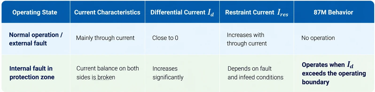
Note: During internal faults, the restraint current is not necessarily very small; its magnitude depends on the fault location, current distribution and the restraint current algorithm adopted by the relay. Therefore, the operating condition of 87M should be judged by whether the differential current exceeds the percentage differential operating boundary, and should not be simply understood as “the restraint current is small during internal faults.”
1.3 Key Parameters of the Percentage Differential Characteristic Curve
- Minimum differential pickup: The starting threshold of differential protection, ensuring sensitivity to low-level internal faults while avoiding the maximum spill current during normal operation.
- Breakpoint current: The transition point of the percentage differential characteristic from one slope section to another. As the restraint current increases, the protection generally adopts a stronger restraint characteristic to improve stability under motor starting, high through-current conditions and CT saturation.
- First slope (Slope 1): Mainly determines the operating characteristic in the low to medium restraint current region, improving stability under normal operation and motor starting while ensuring internal fault sensitivity.
- Second slope (Slope 2): Mainly acts in the large restraint current region, enhancing stability under severe external faults and CT saturation by raising the operating threshold.
1.4 Influence of Motor Starting Transients
- When a motor is started direct-on-line, the starting current may typically reach several times the rated current, for example about 6–8 times, but the actual value depends on the motor design and starting method. The normal motor starting current is fundamentally a through current and, under ideal conditions, should not produce significant differential current. In actual operation, due to transient components in the starting current, CT errors on the two sides, and unequal CT transient saturation, a relatively large spurious differential (spill) current may occur.
- Therefore, the percentage differential characteristic and any additional starting-stability measures of 87M should ensure that the protection remains stable during normal motor starting. Some relays automatically raise the setting or strengthen restraint during starting.
2. Main Purpose and Protection Zone of Motor Differential Protection
- 87M is the main protection for large high-voltage motors and is applicable to key industrial applications such as power, petrochemical, metallurgical and mining industries.
2.1 Main Purpose
- Rapid clearing of internal phase-to-phase short circuits: Tripping instantaneously or with a very short delay, before the short-circuit current damages the stator core and winding insulation.
- Determination of the protection zone: The protection zone of 87M is determined by the installation positions of the CTs on both sides of the differential protection, i.e., the electrical equipment between the two CT groups belongs to the differential protection zone. Therefore, whether the motor feeder cable is included in the protection zone should be judged according to the primary connection and the actual CT installation positions.
2.2 Limitations
- 87M is generally insensitive to turn-to-turn short circuits involving only a small number of turns in the same phase winding, because such faults may not produce a sufficiently large differential current on both sides of the differential protection. Therefore, 87M cannot serve as the main protection for turn-to-turn short circuits. If the turn-to-turn fault further develops into a phase-to-phase fault or other internal fault capable of producing a significant differential current, 87M may operate. In actual engineering practice, comprehensive protection must be achieved by combining negative-sequence current, earth-fault and other applicable motor protection functions.
3. Setting Calculation and Typical Settings of Motor Differential Protection
- The main objectives of motor differential protection setting are to achieve adequate sensitivity to internal faults while maintaining stability during normal operation, motor starting, and external faults. The following are general principles and typical values in engineering practice, mainly referring to the Industrial and Civil Power Distribution Design Manual and relevant setting guidelines.
3.1 Basic Parameters and Balancing Factors
- CT ratio matching: When the CT ratios on both sides are different, the corresponding CT ratio or balancing factor should be set according to the protection relay algorithm, so that the currents on both sides are correctly normalised inside the relay, minimising the spill current during normal operation.
- CT selection: The differential protection CTs should be selected as appropriate protection-class CTs according to the protection relay requirements, and the CT ratio, accuracy limit factor, secondary burden and performance under maximum external through-fault current conditions shall be verified. The CTs on both sides should preferably have similar ratios and transient characteristics to reduce spill current during normal operation, starting and external faults.
3.2 Key Setting Items (Calculation Example Reference Values, Not ANSI/IEC Specified Values)
The following values are only used to explain the setting method. They do not represent the specified values of ANSI 87M or IEC 60255-187-1, nor the recommended values of all protection relays.
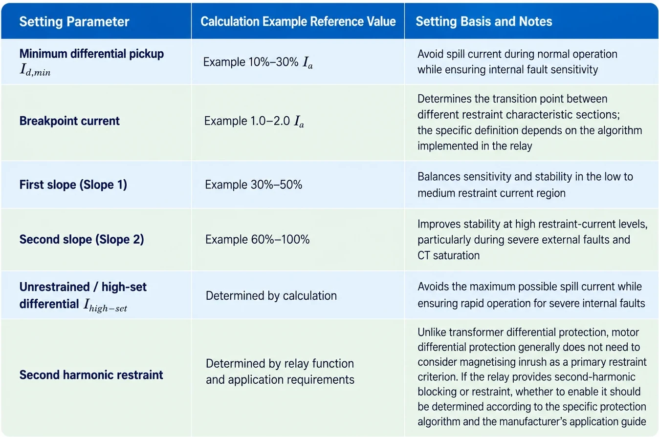
Important Note: Different numerical protection relays may differ significantly in the definition and default values of Slope 1, Slope 2 and breakpoint current. Therefore, the ranges given in this article are only used to explain the setting philosophy, and the final settings must be determined according to the operating characteristics of the specific protection relay and the manufacturer’s technical manual.
3.3 Setting Calculation Example
Consider a 1.4 MW, 11 kV motor for which 87M differential protection is applied because instantaneous overcurrent protection does not provide adequate sensitivity.
(1) Rated current calculation
\[ I_e=\frac{1400}{\sqrt{3}\times11\times0.88\times0.95}\approx88\ \text{A} \]
\( with \cos\varphi\approx0.88,\eta\approx0.95 \)
(2) CT selection
Select a protection-class CT with a ratio of 100/1. The CT rated secondary current is \( I_n=1\ \text{A} \); the CT secondary current at the rated motor current is approximately:
\[ I_{e,sec}=\frac{88}{100}=0.88\ \text{A} \]
(3) Setting calculation
If the differential setting of the relay is based on the CT rated secondary current \( I_n=1\ \text{A} \), and \( I_{d,\min}=0.20I_n \)is taken, then:
\[ I_{d,\min}=0.20\ \text{A} \]
Converted to the primary side:
\[ 0.20\times100=20\ \text{A} \]
This is equivalent to the following percentage of the rated motor current:
\[ \frac{20}{88}\approx0.23I_e \]
(4) Stability verification (simplified example)
Assume that a certain relay adopts the following simplified percentage differential characteristic (only for illustrating the verification approach):
\[ I_{d,trip}=I_{d,\min}+S(I_{res}-I_k),\ \text{when }I_{res}>I_k \]
Take\( I_{d,\min}=0.20\ \text{A},\ I_k=1.20\ \text{A},\ S=0.70 \).
When the external fault through current is\( I_{res}=8\ \text{A} \) (secondary side):
\[ I_{d,trip}=0.20+0.70\times(8-1.20)=4.96\ \text{A} \]
For simplification, assume that under this operating condition, the comprehensive spill current formed by CT errors, measurement errors and other factors is 10% of the through current (this 10% is only a calculation example in this article and is not a general setting value):
\[ I_{unb}=8\times10\%=0.80\ \text{A} \]
Since \( 0.80\ \text{A}<4.96\ \text{A} \), under the above assumptions and simplified operating characteristic, the spill current does not reach the operating boundary, and 87M remains stable.
Note: Actual numerical motor differential protection may adopt single-slope, dual-slope or multi-segment restraint characteristics. The specific operating equation, breakpoints and slope definitions shall be determined according to the protection relay manufacturer’s technical manual. The spill current produced by actual CT saturation cannot be simply generalised as a fixed 10%.
4. Summary
- Motor differential protection (87M) is the main protection for large high-voltage motors. Based on Kirchhoff’s Current Law and the percentage differential principle, it can rapidly clear internal phase-to-phase short circuits. Setting calculations should focus on the minimum differential pickup, breakpoint current, slope coefficients and unrestrained/high-set differential setting. Final settings shall be determined according to the protection relay manual and the actual motor parameters. During setting, special attention should be paid to CT polarity definitions, starting transient spill current and CT saturation during external faults.


