Arc-Flash Protection Relay Solution for Switchgear
1. Internal Arc Fault: A Rapidly Developing and Destructive Fault
- Internal arc faults in MV/LV switchgear are among the most destructive fault types in power distribution systems. When insulation breaks down or a sustained arc forms between conductors, intense light radiation, high temperature and pressure effects are produced within an extremely short time. As the fault duration increases, the released arc energy accumulates rapidly, easily causing severe damage to busbars, circuit breakers, cables and insulating components, and posing a direct threat to on-site personnel and adjacent switchgear.
- In some 6 kV–35 kV medium-voltage distribution systems, due to factors such as system configuration, CT arrangement, protection scope and engineering economics, the busbar may not be equipped with independent busbar differential protection, and busbar faults are mainly cleared by incoming or upstream overcurrent protection. To achieve selective coordination between downstream and upstream protection, backup overcurrent protection usually requires a certain operating time delay, which significantly increases the duration of an internal arc fault.
- Arc-flash protection relays are dedicated protection devices designed for fast detection and fast clearing of internal arc faults in switchgear. They detect the intense light produced by an arc fault and use fault current as a confirmation criterion. Once both operating conditions are met, the relay rapidly issues a trip command, thereby shortening the fault duration and reducing the released arc energy.
- For MV/LV switchgear, GoWaton provides the GWPR220-AF Feeder Arc-Flash Protection Relay and the GWPR350-AF Busbar Arc-Flash Protection Relay. Through the coordination of arc sensors, protection relays and circuit breaker trip circuits, a zone-selective arc protection solution can be established covering feeder panels, circuit breaker compartments, cable compartments, busbar compartments, incomer panels and bus-coupler panels.
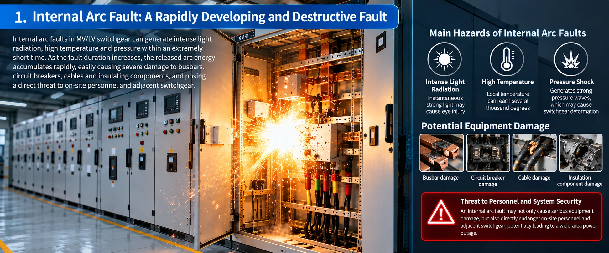
Recommended caption: Internal arc fault zones in switchgear and comparison between conventional protection and arc protection.
Suggested content: A switchgear panel diagram showing the busbar compartment, circuit breaker compartment and cable compartment, with the arc fault risk area highlighted. Alongside it, a side-by-side comparison of the conventional overcurrent protection operating path and the arc protection operating path, illustrating the difference in fault clearing time.
Suggested position: End of Section 1, before Section 2.
2. Why Conventional Protection Schemes Cannot Respond Quickly to Switchgear Arc Faults
- Internal faults in MV/LV switchgear are characterized by fast development and diverse fault locations. Busbar differential protection offers good selectivity and fast operation, but usually requires corresponding CTs and secondary circuits, and its protection zone is determined by the CT installation positions. For some MV/LV distribution systems, considering system scale, retrofit conditions and engineering economics, independent busbar differential protection may not be installed.
- Conventional overcurrent protection mainly operates based on fault current. To ensure selectivity among feeder, incomer and upstream protection, time-grading coordination is usually required. When a fault occurs on the busbar or inside the switchgear, the upstream backup overcurrent protection may need a certain time delay before clearing the fault, while arc energy continues to accumulate as the fault duration increases.
- In addition, arc faults inside switchgear are not limited to the busbar area; they may also occur in the circuit breaker compartment, cable terminations, connection points and other insulation-weak locations. Therefore, a single protection principle alone may not cover all internal fault areas.
- By directly detecting the intense light produced by an arc, arc protection provides a fast means of detecting internal switchgear faults and complements conventional overcurrent protection.
Conventional overcurrent protection operating path:
- Fault current → Overcurrent element pickup → Selective time delay → Circuit breaker trip
Arc protection operating path:
- Arc detection + overcurrent criterion → Arc fault confirmation → Fast trip → Fault isolation
- Therefore, arc protection does not replace overcurrent protection or busbar differential protection; it adds fast detection and fast clearing capability for internal arc faults in switchgear.
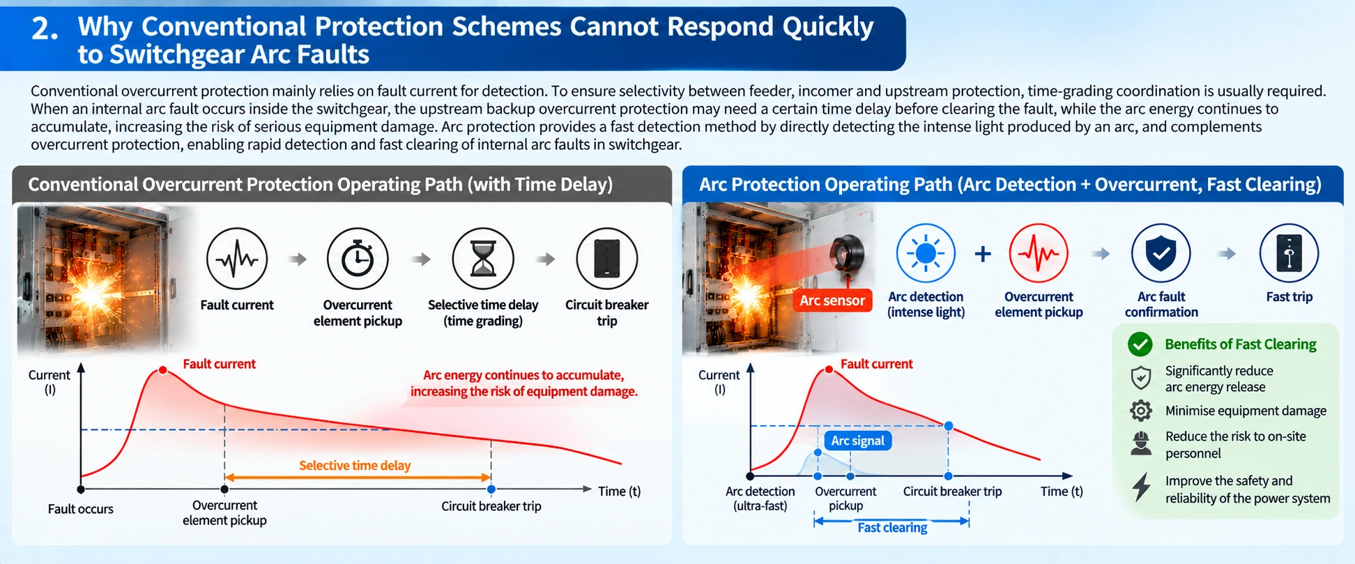
Recommended caption: Operating path comparison between conventional overcurrent protection and arc protection.
Suggested content: A two-track timing diagram. The upper track shows the conventional overcurrent protection path, with the fault current, pickup, selective time delay and breaker trip clearly marked. The lower track shows the arc protection path, with arc detection, overcurrent confirmation, fast trip and fault isolation. The difference in total clearing time should be visually obvious, without labelling specific millisecond values.
Suggested position: End of Section 2, before Section 3.
3. Core Operating Principle: Arc Detection and Overcurrent Dual-Criteria Logic
- Switchgear arc protection typically adopts a combined logic of arc detection and overcurrent supervision.
- When an arc sensor installed inside the switchgear detects abnormal intense light, the arc protection relay receives an arc pickup signal. At the same time, the relay determines through its current measurement channels whether the fault current exceeds the configured pickup value. When both criteria are satisfied, the relay confirms the arc fault and issues a trip command.
Typical protection logic:
- Arc sensor detects intense light + Overcurrent element pickup → Arc fault confirmation → Fast trip command → Circuit breaker clears the faulted zone
- By adopting arc detection and overcurrent dual-criteria logic, the fast detection speed of arc detection can be utilised, while the current condition improves the reliability of protection operation and reduces the risk of maloperation caused by normal lighting, external intense light or other non-fault light sources.
- Depending on specific project requirements, different arc pickup conditions, protection zones, trip targets and intertripping logic can also be designed. The actual protection logic should be determined in accordance with the primary system configuration, switchgear structure and user protection requirements.
- For some low-voltage switchgear, the possibility of visible arcs during normal switching operations must also be considered. Therefore, sensor placement, light detection threshold and current blocking or pickup conditions need to be properly coordinated to avoid misinterpreting normal switching arcs as internal arc faults.
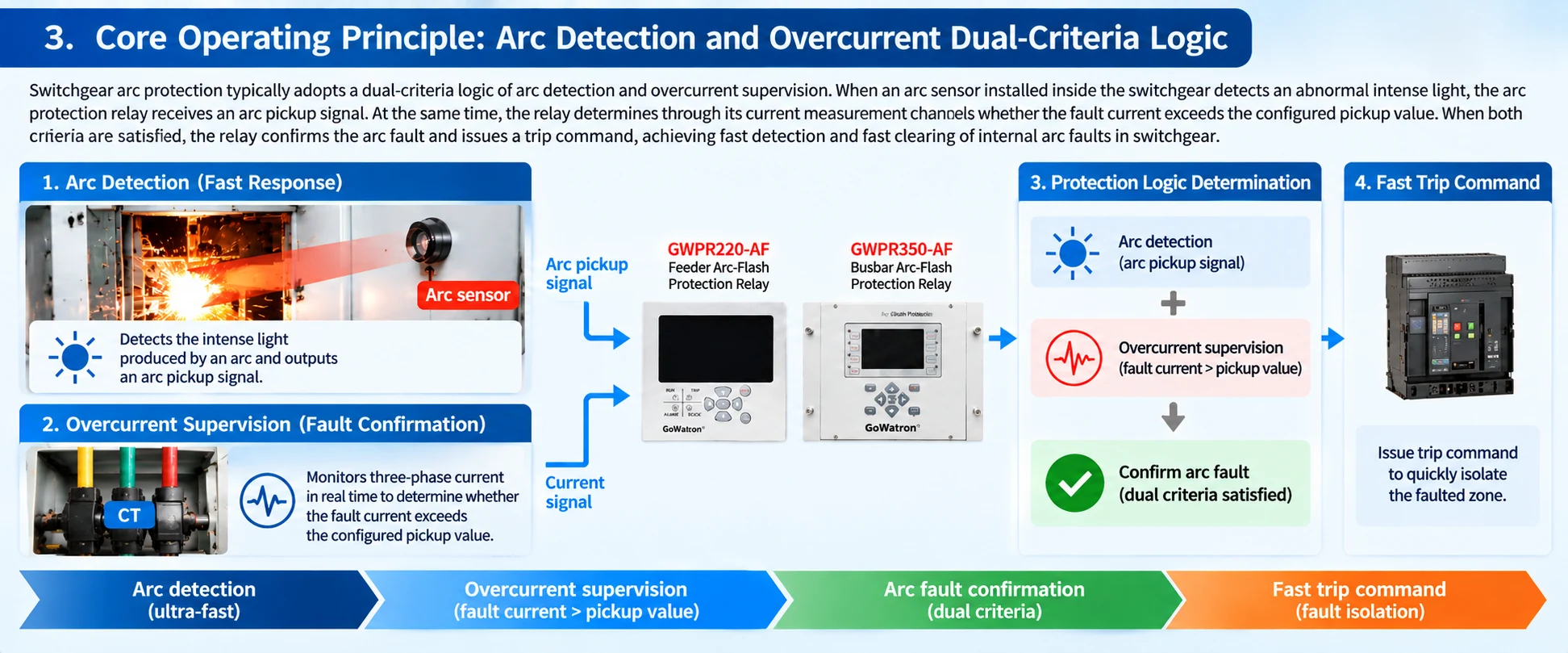
- Suggested content: A logic diagram showing two parallel input branches — the arc sensor branch and the CT current measurement branch — converging into an AND logic gate. The output passes through arc fault confirmation and trip output to the circuit breaker. The arc pickup signal, current pickup value and dual-criteria confirmation should be clearly labelled.
- Suggested position: Within Section 3, after the typical protection logic paragraph and before the low-voltage switchgear paragraph. Alternatively, place at the end of Section 3.
3.1 Why Arc Protection Emphasises Fast Operation
- The energy produced by an internal arc in switchgear is closely related to the fault current and its duration, so shortening the fault duration is an important objective in arc protection design. From arc initiation to final fault clearing, the total time includes arc detection, protection logic processing, trip output operation and circuit breaker opening time. Therefore, engineering design should not only consider the operating speed of the arc protection relay itself, but also comprehensively consider the actual opening time of the circuit breaker. The specific operating times of the GWPR220-AF and GWPR350-AF are subject to the corresponding product technical specifications.
4. System Architecture and Key Components
A complete switchgear arc protection system typically consists of arc sensors, protection relays, current measurement circuits and trip output circuits.
Basic architecture:
Arc sensors + CT current signals → Arc protection relay → Protection logic processing → Trip output → Circuit breaker
Arc sensors are installed in designated switchgear zones to detect the intense light produced by an internal arc. Depending on the switchgear structure and project scheme, arc detection methods suitable for different areas can be adopted to monitor the busbar compartment, circuit breaker compartment and cable compartment.
The protection relay is responsible for receiving arc signals and current signals, executing the arc protection logic, and issuing trip commands to the corresponding circuit breakers according to the faulted zone.
The GoWaton arc protection solution is divided into two main levels according to the protected equipment:
GWPR220-AF Feeder Arc-Flash Protection Relay
Mainly used for feeder panels and local switchgear arc protection, capable of arc detection and trip control for the circuit breaker compartment, cable compartment and related areas.
GWPR350-AF Busbar Arc-Flash Protection Relay
Mainly used for busbar arc protection and multi-bay centralised arc protection, capable of establishing corresponding protection zones and trip logic according to the busbar sectionalising arrangement and the incomer and bus-coupler configuration.
Used together, the two types of devices form a layered architecture combining feeder-level protection and busbar-level protection, covering arc protection requirements from a single feeder panel to an entire busbar system.
5. Zone-Selective Arc Protection
For a distribution system composed of multiple switchgear panels, detecting an arc alone is not sufficient; it is also necessary to determine which protection zone the fault occurred in and which circuit breaker should be tripped. Therefore, zone selectivity is an important part of a switchgear arc protection scheme.
Typical switchgear can be divided into the following protection zones:
- Busbar compartment: busbar and busbar connection area
- Circuit breaker compartment: circuit breaker body, contacts and primary connection area
- Cable compartment: cable termination and cable connection area
After an arc is detected in different zones, different trip logic can be executed according to the primary system configuration.
When an arc fault occurs in a feeder panel or cable compartment, the GWPR220-AF issues a trip command according to the arc detection zone and protection logic. For cable-side faults, the corresponding feeder circuit breaker can usually be tripped. For faults within the circuit breaker compartment or on the source side of the circuit breaker, the trip logic should be determined from the primary system configuration, including whether the upstream incomer or other relevant source circuit breakers must also be tripped.
For busbar faults, when an arc fault occurs in the busbar zone, the GWPR350-AF can issue trip commands to the relevant incomer circuit breaker, bus-coupler circuit breaker or other faulted source circuit breakers according to the preset protection zones and trip matrix.
Through this zone-based protection approach, the arc fault can be cleared quickly while the trip scope is controlled according to the fault location, avoiding unnecessary expansion of the outage area.
6. Complete GWPR220-AF + GWPR350-AF Solution
For a complete MV/LV switchgear system, GoWaton uses the GWPR220-AF and GWPR350-AF to build an arc protection scheme combining feeder-level and busbar-level protection.
The GWPR220-AF is mainly responsible for:
Local protection zones such as feeder panels, circuit breaker compartments and cable compartments.
The GWPR350-AF is mainly responsible for:
Busbar protection zones including the busbar, busbar sectionalising zones and busbar-related areas associated with incomer and bus-coupler circuits.
Complete protection architecture:
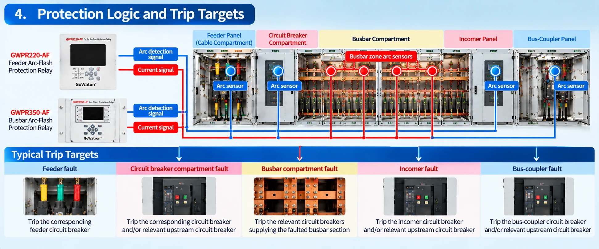
This layered and zone-based arc protection structure can select the corresponding trip targets according to the fault location, and is suitable for single busbar, single busbar with sections, and MV/LV distribution systems with multiple feeder panels.
For specific projects, GoWaton can determine the arc detection zones, required number of protection devices and trip matrix according to the primary system diagram, number of switchgear panels, busbar configuration and circuit breaker arrangement.
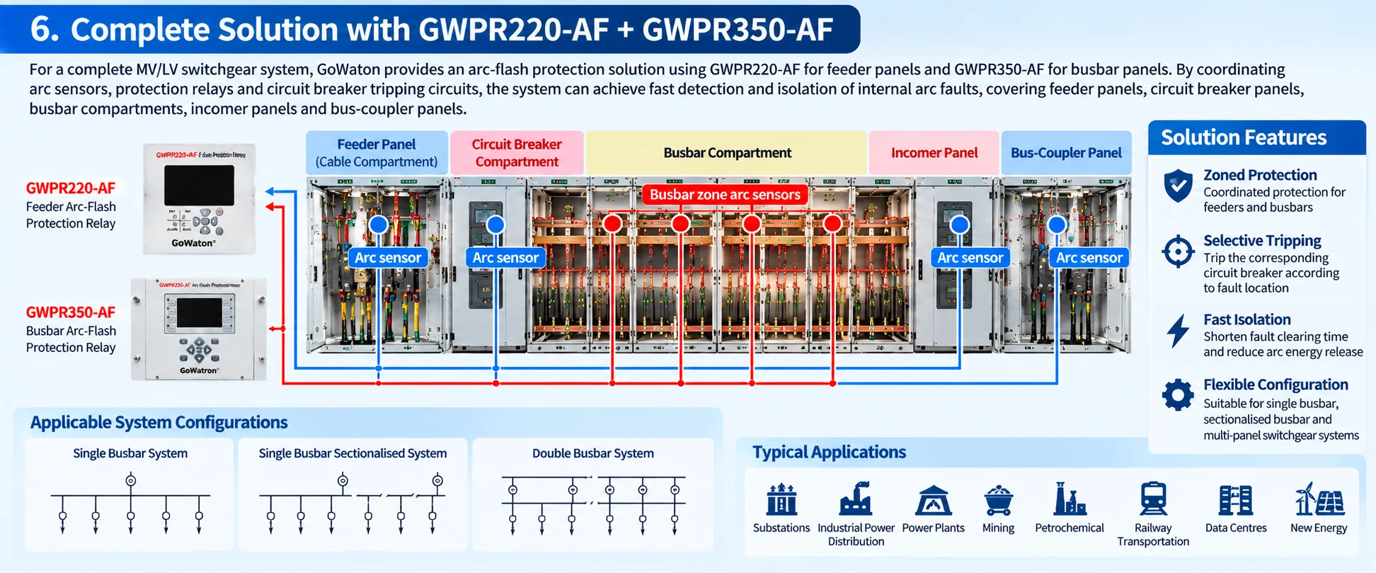
Recommended caption: Complete GWPR220-AF + GWPR350-AF arc-flash protection solution for switchgear.
Suggested content: An overall architecture diagram showing feeder-area arc sensors connected to the GWPR220-AF and busbar-area arc sensors connected to the GWPR350-AF. Both relays feed into the protection logic and trip matrix, which then issues trip commands to the feeder circuit breaker, incomer circuit breaker and bus-coupler circuit breaker. The feeder-level and busbar-level protection layers should be visually separated.
Suggested position: End of Section 6, before Section 7.
7. Health Monitoring and Protection Reliability
- Arc protection must operate rapidly and reliably when an internal arc fault occurs, making the operational status of the relay and its detection circuits particularly important.
- In actual engineering practice, according to the hardware structure of the arc protection system, the sensor connection status, device power supply, protection circuits, trip output circuits and communication status should be monitored, and abnormalities should be identified in a timely manner through alarms and event records.
- For important distribution systems, trip circuit monitoring, device failure alarms and necessary redundancy measures should also be considered in accordance with project reliability requirements.
- The GoWaton arc protection system can be designed according to specific project requirements for arc detection, alarm, trip and communication schemes, so that arc protection coordinates with the existing protective relaying system, switchgear control system and substation automation system.
- The specific self-monitoring functions, number of binary inputs and outputs, communication interfaces and redundancy configuration are subject to the technical specifications of the corresponding GWPR220-AF and GWPR350-AF models.
8. Selection and Engineering Considerations
When selecting arc protection relays, the protection zones, number of sensors and trip targets should be determined according to the switchgear structure, primary system configuration and operating mode, rather than simply configuring protection devices according to the number of switchgear panels.
Sensor placement
Arc sensors should be positioned to cover key internal arc-risk areas, including the busbar compartment, circuit breaker compartment, cable compartment and cable connection areas. The required detection coverage should be determined according to the internal structure of the switchgear.
Current criterion
Provided that the device input requirements and secondary circuit design requirements are met, arc protection can use the corresponding CT current signals for fault confirmation. The current pickup value should be reasonably set in accordance with the system rated current, short-circuit current level and existing protection settings. The pickup setting should be high enough to avoid operation during the maximum normal load current and permissible transient currents, while maintaining sufficient sensitivity to internal arc faults under the minimum system operating condition.
Protection zoning
For multiple switchgear panels, protection zones should be divided according to the busbar sections, incomer, bus-coupler and feeder relationships, so that the correct circuit breakers can be selected for tripping after an arc fault occurs.
Trip matrix
The trip targets corresponding to arc faults in different zones should be clearly defined:
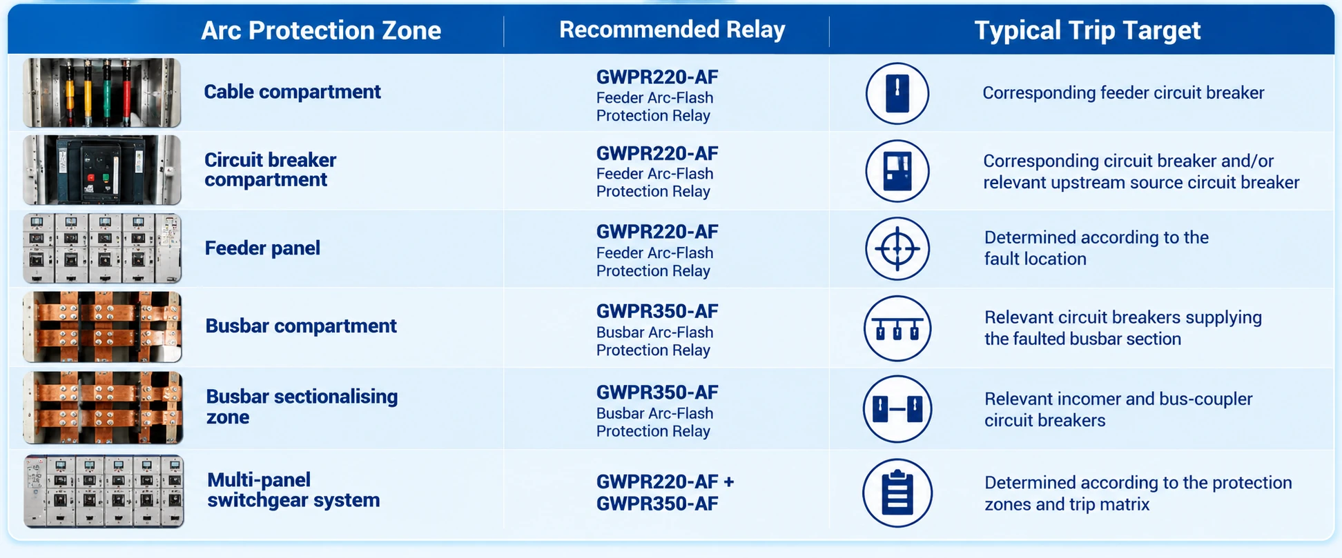
The actual trip targets should be determined according to the primary system configuration, power supply direction and project protection logic.
Communication and system integration
For projects requiring connection to SCADA or a substation automation system, the corresponding communication interfaces and protocols should be selected according to the actual device configuration to upload device status, alarms, event information and other operating data. The specific supported protocols are subject to the corresponding product technical specifications.
9. Typical Applications and Voltage Range
Applicable voltage levels:
6 kV, 10 kV, 11 kV, 20 kV, 22 kV, 33 kV, 35 kV and related low-voltage switchgear.
Typical application scenarios:
- Substation medium-voltage switchgear, industrial power distribution systems, auxiliary power systems of power plants, mining, petrochemical, rail transit, data centres, as well as renewable energy distribution systems such as photovoltaic and wind power.
- In the above application scenarios, arc protection can serve as an important protection measure for fast detection and clearing of internal arc faults in switchgear.
- The GoWaton GWPR220-AF Feeder Arc-Flash Protection Relay and GWPR350-AF Busbar Arc-Flash Protection Relay can be configured in layers according to different protected equipment such as feeder panels, busbars, incomers and bus-couplers, and combined with arc sensors, current criteria and trip matrix to form a complete switchgear arc protection solution.
- For new switchgear projects or retrofit projects of existing distribution systems, the specific arc protection scheme can be determined according to the primary system diagram, switchgear layout, busbar sectionalising method, CT configuration and circuit breaker relationships, so as to minimise the duration of internal arc faults while ensuring protection reliability and selectivity. During project selection, the primary system diagram and switchgear configuration can be provided, and GoWaton will propose arc detection zones, sensor placement and trip matrix recommendations according to the actual system configuration.


