Distributed DC Power Supply Systems: Working Principle, Advantages and Disadvantages, Applications and Selection Guide
1. What Is a Distributed DC Power Supply System?
- A distributed DC power supply system provides DC auxiliary power through individual supply units installed close to the equipment they serve. This localised approach can be particularly useful for medium-voltage switchgear, ring main units (RMUs), compact substations, distribution automation equipment and industrial power distribution systems.
- For clarity, distributed DC power supply in this article refers to locally installed, electrically independent DC power supply units. Each unit supplies its designated loads through a separate DC output circuit.
- This definition distinguishes the arrangement from conventional centralised DC auxiliary power supply systems. It also differs from distributed power architectures (DPAs), where multiple power conversion modules share a common DC busbar.
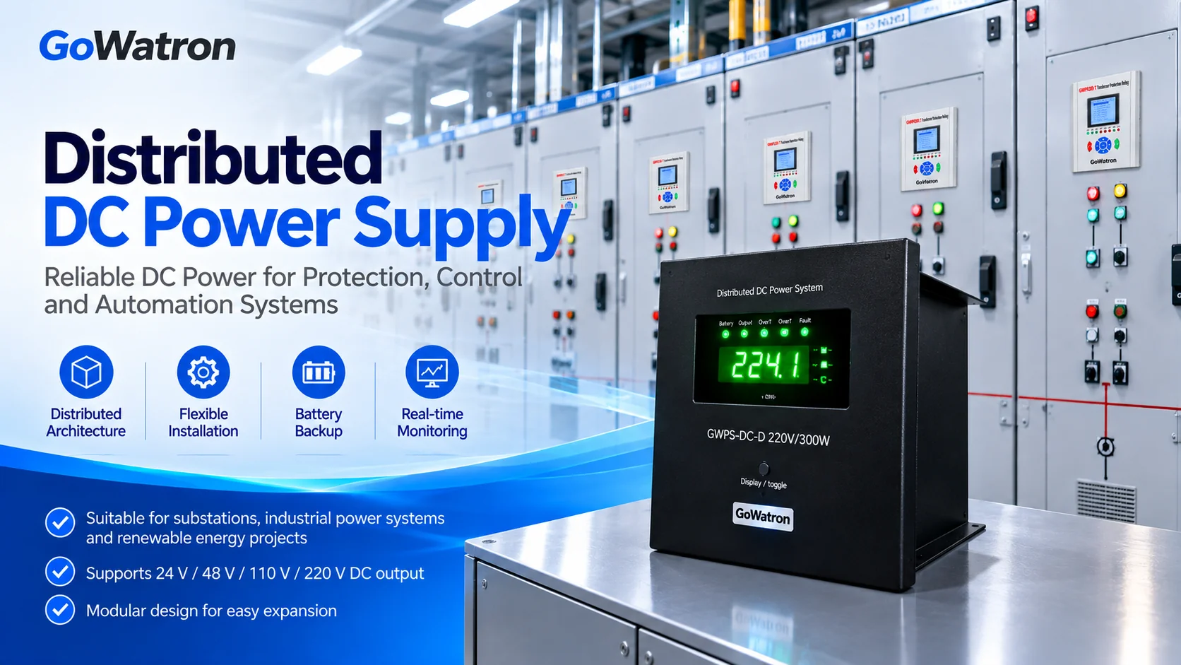
Depending on the design, a distributed DC power supply unit may provide:
- AC/DC rectification and battery charging
- Battery energy storage and charge/discharge management
- DC/DC voltage conversion, depending on the circuit topology
- DC output protection
- Power supply monitoring and fault indication
- Communication interfaces and remote monitoring, where provided
Rechargeable batteries are commonly used for backup energy storage, although other suitable storage technologies may be adopted. The internal circuit arrangement is not necessarily the same across all distributed DC power supply products.
2. Working Principle of Distributed DC Power Supply Systems
To explain how the system operates, the following sections consider a typical arrangement with an AC input supply and battery backup.
2.1 Typical System Architecture
The principal functions and energy paths can be represented as follows:
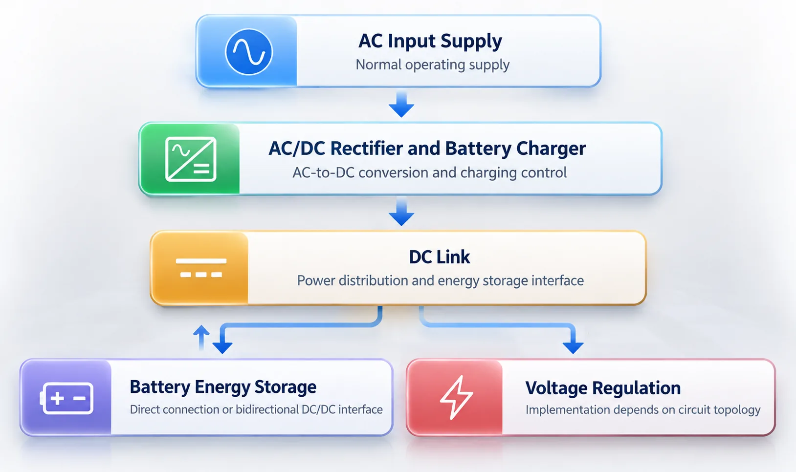
DC Output
Protection relays, circuit-breaker operating circuits, control and communication equipment
Figure 2-1. Functional representation of a typical distributed DC power supply system. The position of the voltage regulation stage is illustrative only. Depending on the circuit topology, voltage regulation may be implemented in the rectifier stage, a battery-side converter, an output-side converter or another regulation stage. The battery may be connected directly to the DC link or through a dedicated bidirectional DC/DC converter. The actual circuit arrangement depends on the product design.
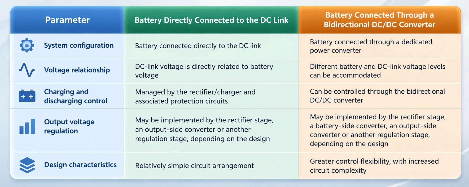
2.2 Common Battery Connection Arrangements
There are two common ways of connecting battery energy storage to the DC power conversion system. Understanding the distinction is important when reviewing a manufacturer’s circuit design.
2.3 Normal Operation
- During normal operation, the AC/DC rectifier and battery charger convert the incoming AC supply into DC power.
- This power supplies the connected DC loads while maintaining the battery state of charge, or restoring it where necessary, according to the charging management strategy.
2.4 Loss of AC Input Supply
- If the AC input supply is interrupted, the battery provides backup power to the connected DC loads through the relevant conversion or distribution circuits.
- The output voltage and any interruption during the transition must remain within the permissible limits of the connected protection, control and communication equipment.
2.5 Restoration of AC Input Supply
- Once the AC input supply is restored, the system returns to normal operation using the primary supply.
- Battery charging then resumes or is adjusted according to the battery condition and the applicable charging strategy.
3. Advantages of Distributed DC Power Supply Systems
The main benefits of distributed DC power supplies arise from placing the supply equipment close to its loads. These benefits can be especially relevant in compact installations or where equipment is spread across several locations.
- Flexible installation; Individual units can be installed close to switchgear panels, control cabinets or other equipment
- Reduced space requirements; May eliminate the need for separate centralised DC power supply panels and dedicated battery cabinets
- Reduced DC cabling; Shorter DC supply circuits can reduce cable quantities, installation work and associated costs
- Improved local fault containment; Where individual supply units are electrically independent and do not share a common DC busbar, local faults can generally be contained within the affected supply unit, provided that appropriate fault isolation and protection arrangements are implemented
- Flexible system expansion; Additional power supply units can be installed as new equipment or loads are added
- Potential cost advantages in small installations; Projects with relatively few switchgear panels may require less initial investment in DC supply equipment and cabling
- Suitability for dispersed installations; Particularly useful where electrical equipment is distributed across separate locations
Modular maintenance; Individual power supply units can be inspected, serviced or replaced independently
These advantages should be assessed in the context of the complete installation. Even where DC outputs are independent, the units may share an AC input source, communication network or other auxiliary infrastructure.
As a result, electrical separation between DC supply units does not eliminate common-cause failure risks.
4. Disadvantages and Limitations of Distributed DC Power Supply Systems
The same decentralised arrangement that provides installation flexibility can also create engineering, operational and maintenance challenges. These need to be considered before selecting a distributed solution.
- Distributed energy storage; Multiple battery installations increase inspection, replacement and maintenance requirements
- Variations in battery service life; Different ambient temperatures inside switchgear panels may result in unequal battery ageing and capacity degradation
- Potentially higher long-term maintenance costs; Maintenance and replacement costs may increase as the number of independent supply units grows
- More complex centralised monitoring; Multiple power supply nodes, communication interfaces and alarms must be managed
- Individual unit failure risk; Without redundancy, failure of a power supply unit may interrupt the DC supply to its associated loads
- Distributed earthing and insulation monitoring; Electrically independent DC systems may require separate insulation monitoring and earth-fault location arrangements
- Limitations for high-power loads; Some compact power supply units may not be suitable for high-power or long-duration DC loads
- Increased cost for extended backup autonomy; Increasing battery capacity at multiple locations may increase total storage requirements, installation space and maintenance costs
- Different environmental conditions; Variations in temperature, humidity and ventilation may affect the reliability and service life of individual units
5. Comparison Between Distributed and Centralised DC Power Supply Systems
Choosing between distributed and centralised DC power supplies requires more than comparing equipment purchase prices. The arrangement of the loads, battery requirements, fault protection and maintenance strategy all influence the most suitable design.
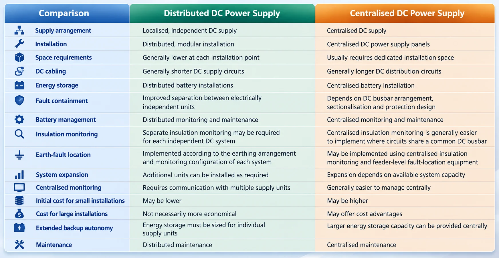
Where extended backup autonomy is required, each distributed supply unit may need a larger battery.
Across an installation, this can increase the combined battery capacity, space requirements and maintenance expenditure compared with a suitably designed centralised arrangement.
For a meaningful comparison, engineers should therefore evaluate the total life-cycle cost, including equipment, installation, DC cabling, battery replacement, maintenance and ongoing operation
6. Typical Applications of Distributed DC Power Supply Systems
6.1 Medium-Voltage Switchgear
Distributed DC power supply systems can be considered for medium-voltage switchgear in 10 kV, 11 kV, 33 kV and 35 kV distribution networks, provided that the selected power supply equipment meets the applicable technical requirements.
Typical DC loads include:
- Protection relays
- Circuit-breaker trip and close circuits
- Control and signalling circuits
- Communication and automation equipment
An important distinction is that the rated voltage of the switchgear main circuit is not the same as the rated output voltage of its DC auxiliary power supply.
The DC output voltage must be selected to suit the rated supply voltage and permissible operating voltage range of the protection devices, circuit-breaker operating mechanisms and other connected DC loads.
Section 6.5 summarises typical DC auxiliary voltage levels. DC 110 V and DC 220 V are commonly used for protection and control in medium-voltage switchgear, although other voltages may be specified by the equipment manufacturer or project requirements.
6.2 Ring Main Units (RMUs)
- Distributed DC power supply systems can support RMUs equipped with motor-operated switching mechanisms, distribution automation terminals and battery backup requirements.
- A local DC supply can serve the operating mechanism, control circuits and automation equipment without requiring all DC loads to be supplied from a centralised installation.
6.3 Compact Substations
- Compact substations often have limited space for auxiliary equipment. A distributed DC power supply can provide local power for protection, control and communication devices within the substation.
- Its modular configuration may also make it easier to integrate the supply into compact electrical equipment and accommodate future expansion.
6.4 Distribution Automation Systems
- Distributed DC power supply systems may supply remote terminal units (RTUs), feeder terminal units (FTUs) and other distribution automation devices.
- Where automation equipment is installed at geographically separated locations, each supply unit can be selected according to the local load profile and specified backup autonomy.
6.5 Typical DC Output Voltage Levels
- Several DC auxiliary supply voltage levels are commonly encountered in electrical power systems.
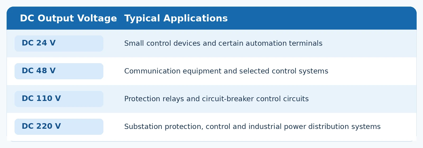
- These are representative engineering configurations, not a specification applicable to every distributed DC power supply product.
- The available output voltage, rated continuous power, short-duration output capability, battery capacity and backup autonomy must be checked against the selected product’s technical data and the actual load requirements.
7. Key Technical Requirements for Distributed DC Power Supply Systems
7.1 Power Supply Reliability
- Reliability of the AC input supply
- Reliability of AC/DC rectifiers and DC/DC converters
- Condition and health of the battery or other energy storage system
- Power supply redundancy and fault isolation arrangements
- Fault detection, protection and alarm functions
7.2 Battery Service Life and Environmental Conditions
- Ambient temperature
- Charging and discharging conditions
- Depth of discharge
- Operating age
- Maintenance practices
7.3 Circuit-Breaker Operating Capability and DC Voltage Dips
- Continuous DC load power
- Peak output power and current
- Trip-coil and closing-coil energisation duration
- Spring-charging motor current and operating duration
- Required operating sequences and repeated operating capability
- Operating capability at the minimum permissible battery voltage
- DC output voltage dips during switching operations
- DC short-circuit current, current-limiting characteristics and protection coordination
7.4 Battery Backup Autonomy Calculation
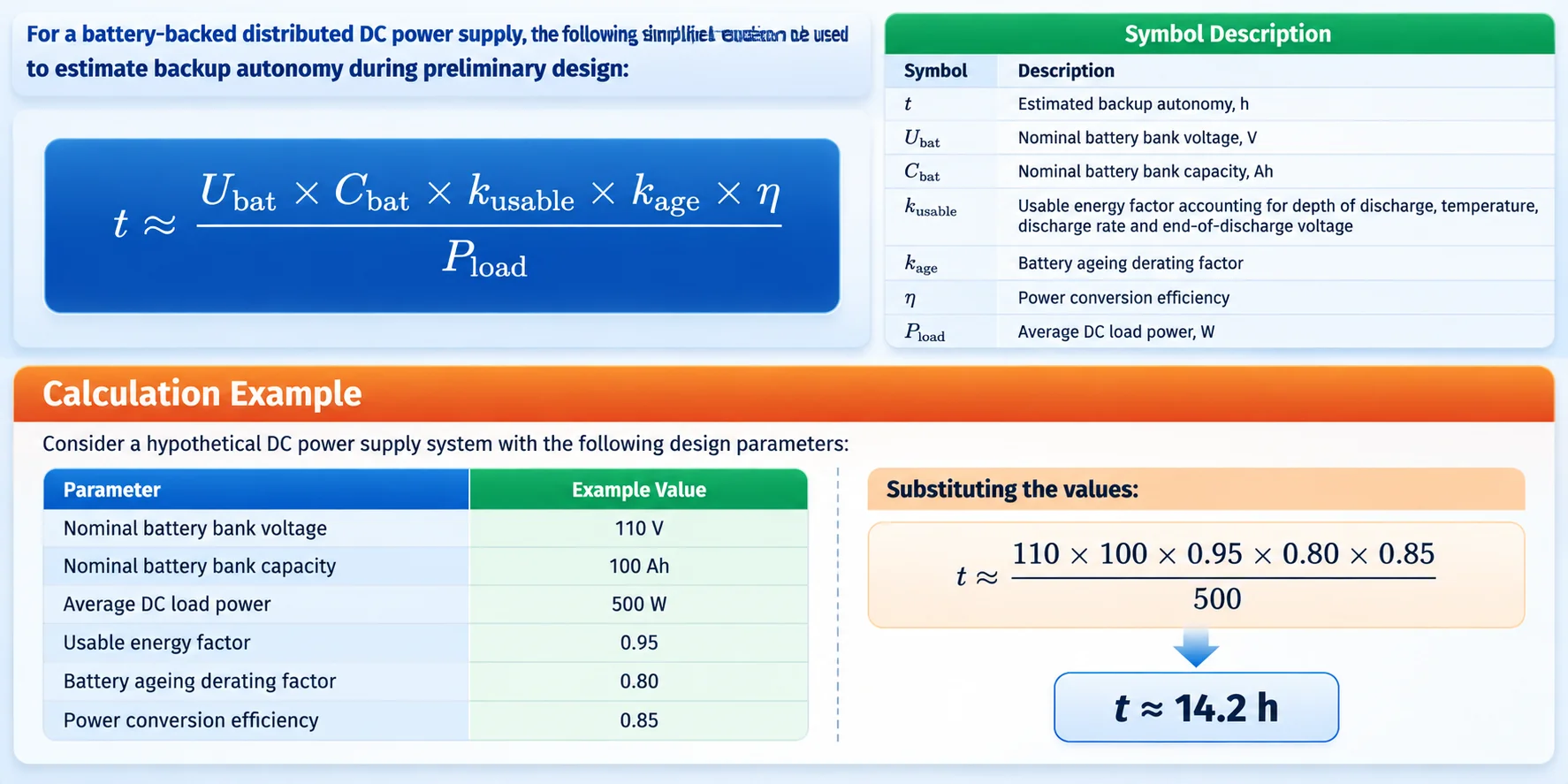
- This is a simplified theoretical estimate, not a guaranteed backup duration for a particular product.
- The 110 V, 100 Ah battery bank is included only to demonstrate the calculation method. It should not be interpreted as a typical battery configuration for all distributed DC power supplies.
- For detailed engineering design, battery sizing must be verified against the applicable discharge characteristics, taking account of discharge rate, minimum operating temperature, permissible end-of-discharge voltage, load variations and available capacity at the specified end of service life.
- Care is also needed when applying correction factors. The usable energy factor and battery ageing derating factor should be defined consistently so that the same reduction in available capacity is not counted twice.
- For example, if the usable energy factor already accounts for reduced capacity at the minimum design temperature, the ageing factor should not include that same temperature-related reduction again.
- The factors in this example are illustrative. Actual values must be established from the relevant battery specifications and project design requirements.
7.5 Remote Monitoring and Communication
Where an installation contains multiple distributed DC power supply units, centralised supervision can help operators monitor the condition of individual supplies and identify faults.
Depending on the project requirements and product configuration, monitoring functions may include:
- AC input supply status
- DC output voltage and current
- Battery condition and charging/discharging alarms
- Power conversion module faults
- Abnormal DC output conditions
- Remote communication and centralised fault indication
The supported communication interfaces, protocols and monitoring functions must be confirmed from the applicable product documentation.
7.6 DC Earthing and Insulation Monitoring
- A distributed DC power supply installation may contain several electrically independent DC systems.
- The appropriate insulation monitoring and earth-fault location arrangements depend on the earthing configuration of each system.
- For unearthed DC systems that require insulation monitoring, suitable insulation monitoring devices should be provided in accordance with the applicable standards and engineering requirements.
- If multiple independent DC systems have separate insulation monitoring devices, their operating principles, settings and communication arrangements should be coordinated to avoid incompatibility or mutual interference.
- For systems using other earthing arrangements, the fault detection and protective measures should be selected according to the electrical characteristics and protection requirements of those systems.
8. Selection Guide for Distributed DC Power Supply Systems
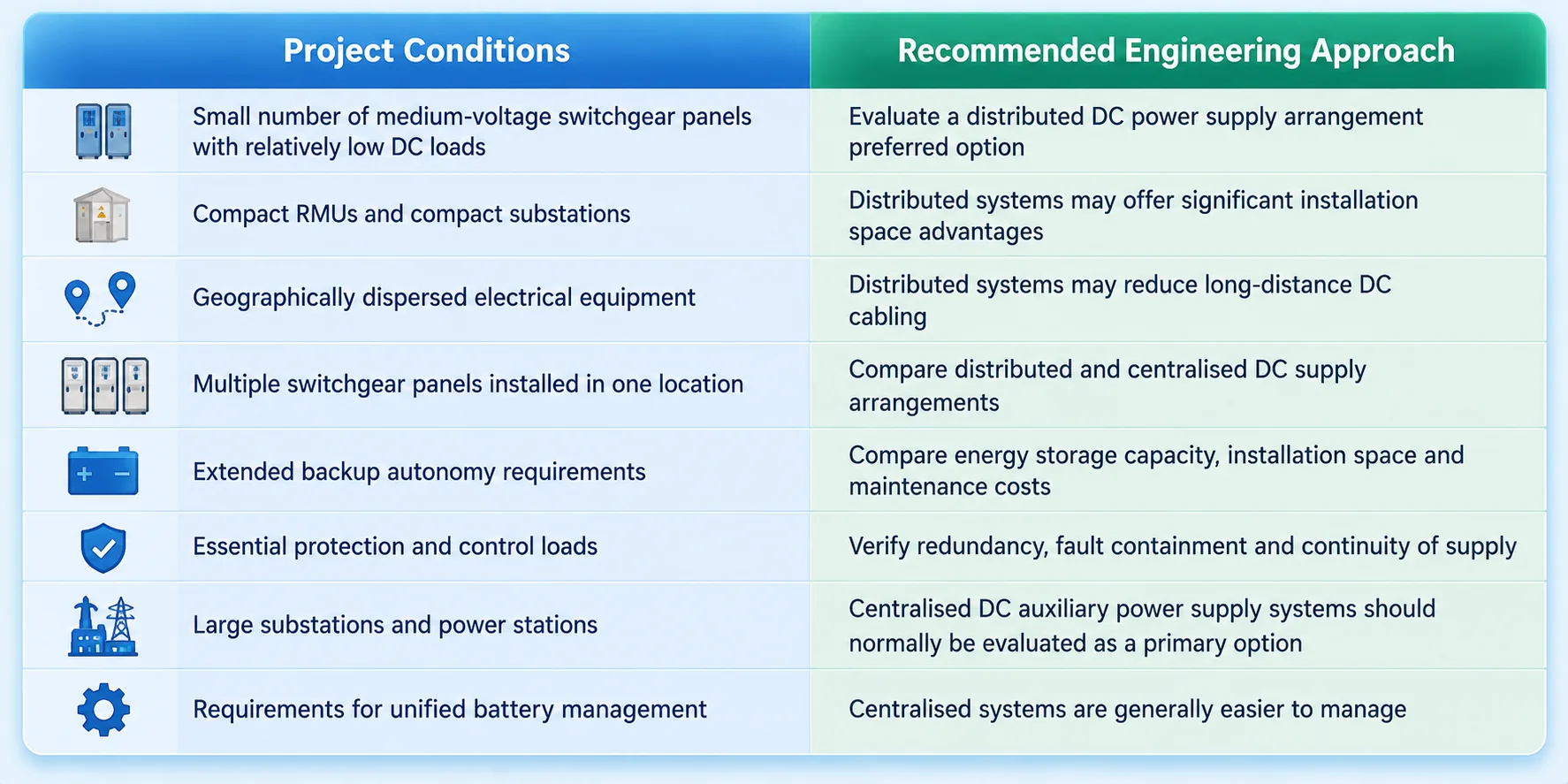
The best supply arrangement depends on how the equipment is installed, where the loads are located and what level of reliability and backup autonomy the project requires.
The following table provides a practical starting point for comparing distributed and centralised solutions.
9. Conclusion
Distributed DC power supply systems provide localised DC auxiliary power through independent units installed near their connected loads. They are particularly relevant to medium-voltage switchgear, RMUs, compact substations and distribution automation equipment.
Their principal advantages are flexible installation, reduced space requirements, shorter DC supply circuits and modular expansion. Where supply units are electrically independent and correctly protected, the arrangement can also help contain local faults.
However, distributed energy storage introduces additional battery management, monitoring and maintenance requirements. Differences in battery ageing and environmental conditions can affect backup performance, while larger installations may face higher overall life-cycle costs.
For a battery-backed distributed DC power supply system, the engineering assessment should cover the following technical and economic requirements:
- Continuous output power and short-duration operating capability.
- DC voltage dips during circuit-breaker opening and closing operations.
- DC short-circuit current, current-limiting characteristics and protection coordination.
- Battery capacity, backup autonomy and service life.
- Continuity of DC supply following loss of the AC input.
- Remote monitoring, communication and fault alarm functions.
- Earthing arrangements, insulation monitoring and earth-fault location.
- Environmental suitability and maintenance requirements.
- zTotal life-cycle cost.
Neither distributed nor centralised DC power supply systems are inherently superior in every application. The appropriate solution depends on project size, load distribution, supply reliability, backup autonomy, installation constraints and total life-cycle cost.


