Undervoltage Protection (ANSI 27): Working Principle, Functions and Setting Calculations
1. What Is Undervoltage Protection (ANSI 27)?
Undervoltage protection (ANSI 27) is a voltage-based protection function designed to detect when the measured system voltage falls below a configured threshold for a specified period.
It is widely used in medium-voltage and low-voltage power distribution systems, industrial electrical installations, substations, motor control systems and power generation facilities.
The principal purposes of undervoltage protection include:
- Detecting sustained or abnormal voltage reductions
- Protecting electrical equipment against unacceptable low-voltage operating conditions
- Initiating circuit-breaker tripping where required
- Providing alarm signalling and control interlocking
- Initiating load shedding under specified operating conditions
- Coordinating with other protection and automation functions
Undervoltage protection must be distinguished from instantaneous voltage-dip detection and power quality monitoring. Although these functions may use similar voltage measurements, their operating criteria, time delays and intended responses can differ.
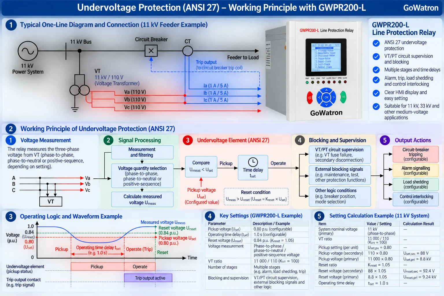
2. Working Principle of Undervoltage Protection
2.1 Basic Operating Principle
An undervoltage protection relay continuously monitors one or more voltage quantities supplied by voltage transformers (VTs) or directly measured through suitable voltage inputs.
The measured voltage may be:
- Phase-to-phase voltage
- Phase-to-neutral voltage
- Positive-sequence voltage
- Another voltage quantity supported by the relay’s protection algorithm
When the selected measured voltage falls below the configured pickup voltage, the undervoltage element picks up, provided that all relevant enabling and blocking conditions are satisfied.
The basic pickup criterion is:
\[ \boxed{U_{\mathrm{meas}}<U_{\mathrm{set}}} \tag{1} \]
Where:
- \( U_{\mathrm{meas}} \) = measured voltage used by the protection element
- \( U_{\mathrm{set}} \) = configured pickup voltage
The protection element may initiate an operating timer once the pickup condition is satisfied.
If the undervoltage condition persists for the configured operating time, the relay initiates the assigned protection or control action.
The final response may include circuit-breaker tripping, alarm signalling, load shedding or control interlocking, depending on the application.
2.2 Pickup Voltage and Operating Time
- Pickup voltage; Voltage threshold below which the protection element starts operating
- Operating time delay ; Configured time for which the pickup condition must persist before the assigned action is initiated
2.3 Reset Voltage and Hysteresis
\[ k_{\mathrm{reset}}= \frac{U_{\mathrm{reset}}}{U_{\mathrm{set}}} \tag{2} \]
\[ U_{\mathrm{set}}=0.80U_{\mathrm{n}} \]
\[ k_{\mathrm{reset}}=1.05 \]
\[ U_{\mathrm{reset}}=0.80\times1.05U_{\mathrm{n}} \]
\[ \boxed{U_{\mathrm{reset}}=0.84U_{\mathrm{n}}} \tag{3} \]
3. Main Functions of Undervoltage Protection
3.1 Definite-Time Undervoltage Protection
Definite-time undervoltage protection operates after a preset delay when the measured voltage remains below the configured pickup voltage.
The operating condition can be expressed as:
\[ U_{\mathrm{meas}}<U_{\mathrm{set}} \]
for the configured duration:
\[ t\geq t_{\mathrm{set}} \]
Where:
– \(t\) = elapsed time during which the pickup condition remains satisfied
– \(t_{\mathrm{set}}\) = configured operating time delay
This function is suitable for applications where short-duration voltage dips should be tolerated but sustained undervoltage conditions require a response.
3.2 Multi-Stage Undervoltage Protection
- Some numerical protection relays provide multiple undervoltage protection stages.
- Different stages may be configured with separate pickup voltages, operating time delays and assigned actions.
For example:
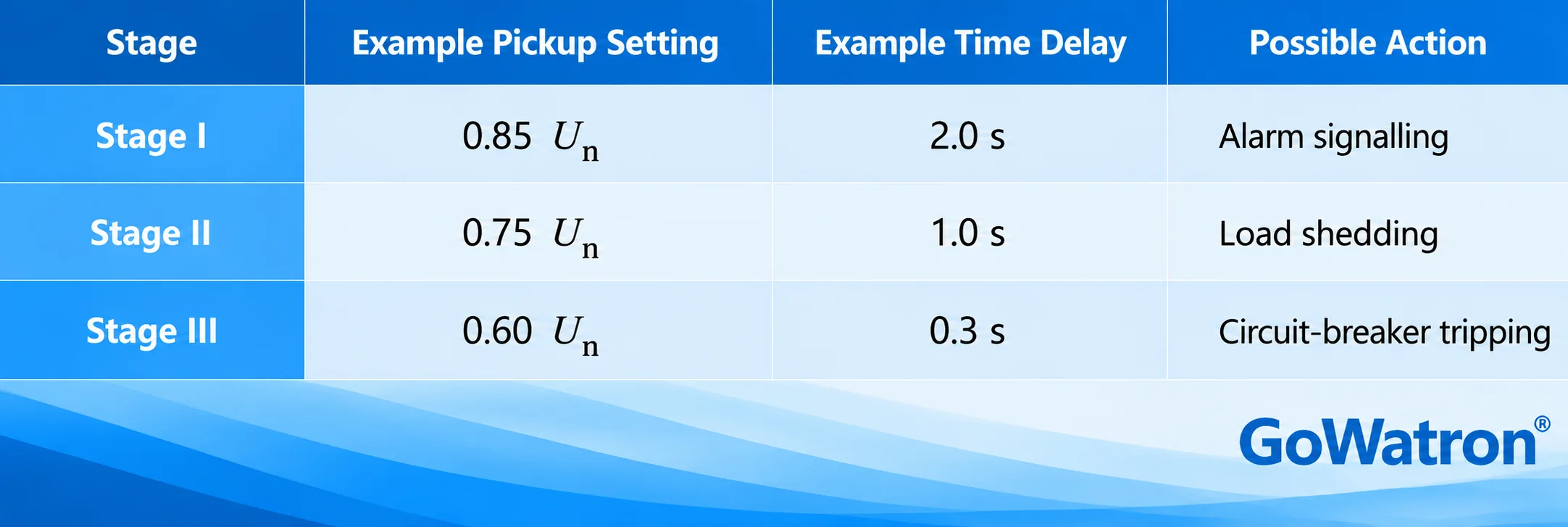
These values are illustrative only. They are not universal recommended settings and must not be applied without considering the system operating requirements and protection coordination.
3.3 Undervoltage Load Shedding
Undervoltage load shedding is used to disconnect selected loads when the system voltage falls below specified limits.
Its purpose is to reduce electrical loading and, where appropriate, support voltage recovery.
A load-shedding scheme may incorporate:
- Multiple undervoltage stages
- Independent operating time delays
- Load priority classification
- Frequency-related supervision or combined logic
- VT/PT circuit supervision and blocking
- External enabling and blocking signals
Load shedding must be coordinated with the overall power system operating strategy.
The presence of ANSI 27 protection does not automatically mean that a relay includes a complete load-shedding scheme.
3.4 Alarm Signalling and Control Interlocking
- Undervoltage protection may also be configured to provide alarm signalling without initiating circuit-breaker tripping.
- In industrial power systems, undervoltage elements may be incorporated into control interlocking schemes to prevent equipment operation under unsuitable voltage conditions.
- The action should be selected according to the application and the equipment’s permissible operating voltage range.
4. Applications of Undervoltage Protection
4.1 Medium-Voltage Distribution Systems
Undervoltage protection is commonly applied in 11 kV and 33 kV distribution systems.
Typical applications include:
- Feeder protection and control
- Substation busbar voltage supervision
- Transformer-associated protection and control schemes
- Industrial distribution networks
- Automatic bus transfer schemes
- Load-shedding systems
The protection settings must be coordinated with the normal operating voltage range, expected voltage dips and the applicable system protection philosophy.
4.2 Motor Protection
Induction motors may experience increased current, reduced torque and operating instability under undervoltage conditions.
Undervoltage protection can be used to initiate alarm signalling, motor disconnection or restart inhibition according to the motor protection scheme.
Motor protection settings should consider:
- Minimum permissible operating voltage
- Motor starting and reacceleration requirements
- Expected voltage-dip duration
- Process continuity requirements
- Thermal and mechanical operating limitations
4.3 Transformer and Substation Applications
In substations, undervoltage protection may form part of:
- Busbar voltage supervision
- Automatic bus transfer logic
- Load-shedding schemes
- Protection and control interlocking
- Auxiliary system supervision
The protection function should be coordinated with the relevant circuit-breaker operating sequence and other system automation functions.
4.4 Power Generation and Renewable Energy Systems
- Undervoltage protection may be used in generator protection and renewable energy installations.
- However, its settings must be coordinated with the applicable grid connection requirements and voltage ride-through obligations.
- A voltage dip should not automatically cause disconnection where the connected equipment is required to remain operational during specified disturbances.
5. Undervoltage Protection Setting Principles
5.1 Selection of Pickup Voltage
The pickup voltage should be selected below the minimum voltage expected during permissible normal operation, while remaining sufficiently sensitive to detect unacceptable undervoltage conditions.
A simplified engineering relationship is:
\[ U_{\mathrm{set}}<U_{\mathrm{min,normal}} \tag{4} \]
Where:
– \(U_{\mathrm{set}}\) = configured pickup voltage
– \(U_{\mathrm{min,normal}}\) = minimum normal operating voltage
This relationship is a preliminary selection principle rather than a complete setting rule.
The final setting should consider measurement accuracy, operating tolerances, voltage transformer characteristics, system operating variations and equipment requirements.
5.2 Selection of Operating Time Delay
The operating time delay should prevent unnecessary operation during acceptable short-duration voltage dips.
The selected delay should consider:
- Expected voltage-dip duration
- Equipment voltage ride-through capability
- Motor starting and reacceleration conditions
- Upstream and downstream protection coordination
- Automatic transfer and restoration schemes
- Required system operating response
A longer time delay may improve tolerance to temporary voltage reductions but can also delay the required protective action.
5.3 Voltage Measurement Method
The selected voltage measurement method affects the sensitivity and operating behaviour of undervoltage protection.
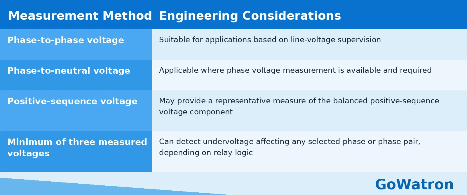
The measurement quantity and phase-selection logic must be confirmed from the relay documentation.
5.4 VT/PT Circuit Supervision and Blocking
VT/PT circuit supervision is important for preventing incorrect undervoltage protection operation caused by voltage measurement circuit abnormalities.
Depending on the protection relay design, VT/PT circuit supervision may detect conditions such as:
- VT fuse failure
- Secondary circuit disconnection
- Loss of one or more voltage measurement signals
- Other abnormal voltage measurement conditions
When a relevant abnormal condition is detected, the protection relay may block the associated undervoltage element and issue an alarm according to the configured protection logic.
VT fuse failure refers to a specific fault condition. VT/PT circuit supervision and blocking refers to the broader supervision and blocking function.
The supervision logic should distinguish, as far as practicable, between an actual system undervoltage condition and a voltage measurement circuit failure.
6. Undervoltage Protection Setting Calculation
6.1 Primary and Secondary Voltage Conversion
When the relay measures voltage through a VT, the relationship between primary and secondary voltage must be considered.
For corresponding voltage quantities:
\[ U_{\mathrm{sec}}= \frac{U_{\mathrm{pri}}}{K_{\mathrm{VT}}} \tag{5} \]
Where:
\(U_{\mathrm{sec}}\) = secondary voltage
\(U_{\mathrm{pri}}\) = primary voltage
\(K_{\mathrm{VT}}\) = applicable VT voltage transformation ratio
The voltage quantities must be expressed on consistent bases, such as primary and secondary phase-to-phase voltages.
6.2 Per-Unit Voltage Setting
The per-unit pickup setting can be expressed as:
\[ U_{\mathrm{set,pu}}= \frac{U_{\mathrm{set}}}{U_{\mathrm{base}}} \tag{6} \]
Where:
\(U_{\mathrm{set,pu}}\) = per-unit pickup setting
\(U_{\mathrm{set}}\) = configured pickup voltage
\(U_{\mathrm{base}}\) = voltage base corresponding to the relay’s selected measurement quantity
For example, a setting of:
\[ U_{\mathrm{set,pu}}=0.80 \]
corresponds to 80% of the selected voltage base.
6.3 Example: 11 kV System
Consider an 11 kV distribution system with a VT ratio of:
\[ \frac{11\,000}{110} \]
The corresponding voltage transformation ratio is:
\[ K_{\mathrm{VT}}=100 \]
Assume that the required undervoltage pickup setting is:
\[ U_{\mathrm{set,pu}}=0.80 \]
For a nominal secondary phase-to-phase voltage of 110 V:
\[ U_{\mathrm{set,sec}}=110\times0.80 \]
\[ \boxed{U_{\mathrm{set,sec}}=88\ \mathrm{V}} \tag{7} \]
The corresponding primary phase-to-phase pickup voltage is:
\[ U_{\mathrm{set,pri}}=11\,000\times0.80 \]
\[ \boxed{U_{\mathrm{set,pri}}=8.8\ \mathrm{kV}} \tag{8} \]
These results apply to the assumed voltage measurement base and VT configuration.
If the relay uses phase-to-neutral voltage or positive-sequence voltage, the appropriate measurement definition and scaling must be used.
6.4 Example: 33 kV System
Consider a 33 kV distribution system with a VT ratio of:
\[ \frac{33\,000}{110} \]
Therefore:
\[ K_{\mathrm{VT}}=300 \]
Assume an undervoltage pickup setting of:
\[ U_{\mathrm{set,pu}}=0.85 \]
The secondary phase-to-phase pickup voltage is:
\[ U_{\mathrm{set,sec}}=110\times0.85 \]
\[ \boxed{U_{\mathrm{set,sec}}=93.5\ \mathrm{V}} \tag{9} \]
The corresponding primary phase-to-phase pickup voltage is:
\[ U_{\mathrm{set,pri}}=33\,000\times0.85 \]
\[ \boxed{U_{\mathrm{set,pri}}=28.05\ \mathrm{kV}} \tag{10} \]
The calculated values are illustrative. Actual settings must be verified against the system voltage limits and the relay’s voltage measurement configuration.
7. Protection Coordination and Blocking Logic
7.1 Coordination with Overcurrent Protection
- Undervoltage protection and overcurrent protection detect different electrical conditions.
- Overcurrent protection responds to excessive current, whereas undervoltage protection responds to a reduction in the selected measured voltage.
- These functions may operate independently or be combined in a protection and control scheme.
7.2 Coordination with Automatic Bus Transfer
- Undervoltage protection is frequently used to initiate automatic bus transfer schemes.
- However, bus transfer operation should not depend solely on an undervoltage pickup signal.
Additional conditions may include:
- Incoming supply availability
- Busbar voltage conditions
- Circuit-breaker position
- Protection blocking signals
- Transfer permissive conditions
- Synchronism or residual voltage conditions, where applicable
7.3 Coordination with Load Shedding
- Undervoltage load shedding should be coordinated with system operating conditions and the load priority scheme.
- Multiple stages may be used to disconnect loads progressively.
- The settings should be selected to avoid unnecessary load shedding during acceptable short-duration voltage dips.
7.4 VT/PT Circuit Supervision and Protection Blocking
- A failure in the voltage measurement circuit can cause the relay to detect an apparent undervoltage condition even when the primary system voltage is normal.
- For this reason, VT/PT circuit supervision and blocking may be used to prevent incorrect operation.
- The blocking arrangement should be designed according to the relay’s available supervision functions and the overall protection philosophy.
8. Common Setting Problems and Engineering Considerations
8.1 Pickup Voltage Set Too High
- If the pickup voltage is set too close to the normal operating voltage, the protection element may operate unnecessarily during permissible system voltage variations.
- This can lead to unwanted alarm signalling, circuit-breaker tripping or load shedding.
8.2 Operating Time Delay Set Too Short
- An excessively short time delay may cause the protection element to operate during temporary voltage dips that the connected equipment is designed to tolerate.
- The time delay should therefore be coordinated with the relevant equipment voltage ride-through requirements.
8.3 Repeated Pickup and Reset Operations
- When the measured voltage fluctuates around the configured pickup voltage, repeated pickup and reset operations may occur if the reset characteristic is not appropriately configured.
- Suitable hysteresis and reset settings can reduce this behaviour.
- The reset ratio and reset voltage should be selected according to the relay characteristics and the operating requirements of the protected system.
8.4 Incorrect VT/PT Configuration
- Incorrect VT ratios, voltage measurement selection or phase-voltage configuration can result in inaccurate undervoltage pickup settings.
- The configured VT ratio and selected measurement quantity must be checked before the protection settings are applied.
8.5 Inadequate VT/PT Circuit Supervision
- If VT/PT circuit supervision is not correctly configured, voltage measurement circuit failures may be interpreted as genuine undervoltage conditions.
- For example, VT fuse failure may cause an abnormal voltage measurement and potentially initiate an incorrect protection response.
- The supervision and blocking functions should be verified during protection testing and commissioning.
8.6 Inappropriate Protective Action
- Not every undervoltage condition requires immediate circuit-breaker tripping.
- Depending on the application, the appropriate response may be alarm signalling, load shedding, control interlocking or delayed tripping.
- The assigned action should be coordinated with the equipment operating requirements and the overall system protection scheme.
9. Conclusion
- Undervoltage protection (ANSI 27) is an important protection and control function in electrical power systems. It detects when the selected measured voltage falls below a configured pickup threshold and initiates the required response according to the protection logic.
- Reliable operation depends on selecting appropriate pickup voltage, reset voltage, operating time delay, voltage measurement method and VT/PT circuit supervision settings.
- For 11 kV and 33 kV distribution systems, the protection settings must also be coordinated with circuit-breaker operating requirements, equipment voltage ride-through capability, automatic bus transfer schemes and load-shedding arrangements.
- Undervoltage protection should be configured according to the actual electrical system requirements rather than applying fixed voltage thresholds or time delays across different installations.
The final settings should be verified through engineering calculations, protection coordination studies and commissioning tests before the protection scheme is placed into service.


