Where Are ANSI 50/51 Overcurrent Protection Relays Used?
1. What Is ANSI 50/51 Overcurrent Protection?
An overcurrent protection relay continuously measures the current flowing through a power circuit. When the measured current exceeds the configured pickup value and the applicable operating criteria are satisfied, the relay issues a trip command to the circuit breaker. This isolates the faulty equipment or circuit section and prevents the fault from developing into a wider system disturbance.
According to the ANSI/IEEE device function numbering system:
- ANSI 50 — Instantaneous Overcurrent Protection: operates when the current exceeds the pickup setting, with no intentional time delay. It is primarily used for the rapid clearance of high-current faults close to the protection location.
- ANSI 51 — Time Overcurrent Protection: operates with a definite-time or inverse-time characteristic. It is primarily used to achieve selective coordination between upstream and downstream protection devices.
ANSI 50/51 typically serves as the primary phase-fault protection for radial distribution feeders. It is also widely used as backup protection for transformers, generators, motors and other electrical equipment.
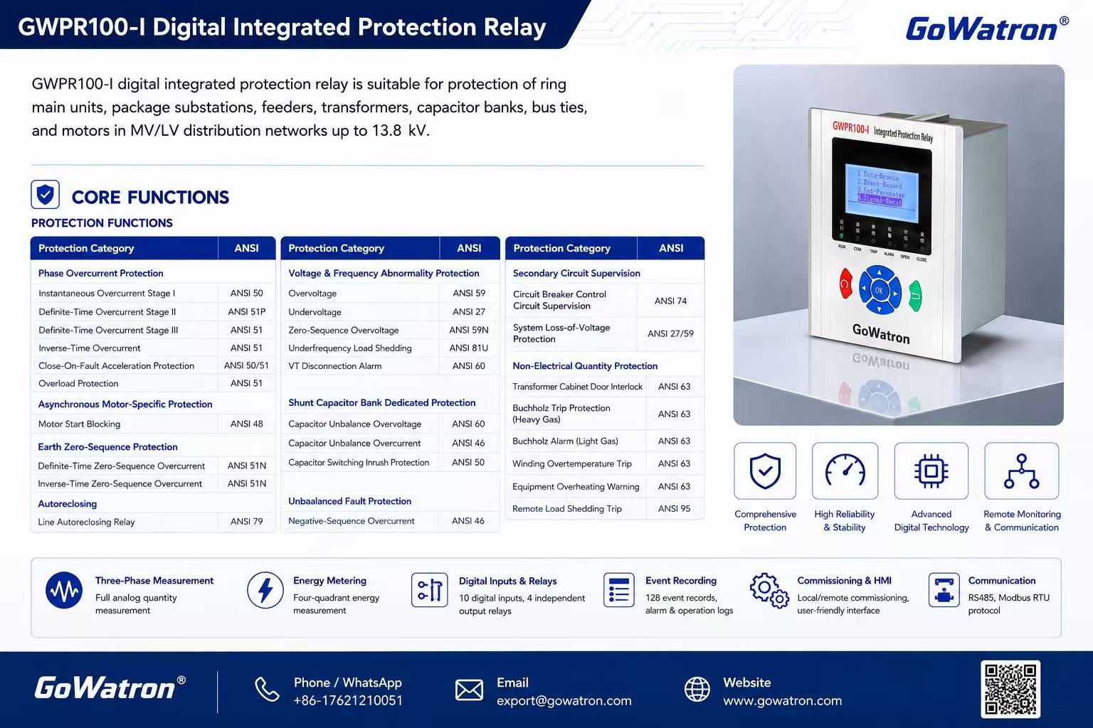
2. Main Applications of ANSI 50/51 Overcurrent Protection
2.1 Distribution Lines and Outgoing Feeders
ANSI 50/51 protection is widely used for incoming and outgoing feeders in substations, switching stations, distribution substations and industrial power systems.
It is primarily used to detect:
- Phase-to-phase faults;
- Three-phase faults;
- Abnormal phase overcurrents;
- Faults not cleared by downstream protection or circuit breakers.
ANSI 50 provides rapid clearance of high-current faults close to the relay location. ANSI 51 provides time-delayed protection and backup for downstream circuits through coordinated pickup settings and operating times.
In radial distribution systems, the pickup settings and operating times of successive relays can be coordinated so that the circuit breaker closest to the fault operates first. This isolates the smallest practicable section of the network and minimises the extent of the outage.
2.2 Transformer Protection
ANSI 50/51 protection can be applied to distribution transformers, station service transformers and power transformers for phase-fault and backup protection.
Typical applications include:
- High-voltage-side overcurrent protection;
- Low-voltage-side overcurrent protection;
- Backup protection for external faults;
- Backup protection for internal transformer faults;
- Backup protection when downstream protection or a circuit breaker fails to clear a fault.
For large or critical transformers, ANSI 87T transformer differential protection is normally used as the primary protection against internal faults, while ANSI 50/51 provides backup protection.
Relay settings should take account of transformer rated current, permissible overload capability, magnetising inrush current, current-transformer ratio and performance, available short-circuit current, and coordination with upstream and downstream protection. The instantaneous element must be set carefully to avoid unwanted operation during transformer energisation.
For large transformers, overcurrent protection may not provide sufficient sensitivity for low-magnitude internal faults, particularly when the available fault current is limited by system or transformer impedance. Transformer differential protection therefore remains the preferred primary protection for internal phase faults, while ANSI 50/51 is generally applied as backup protection.
2.3 Motor Protection
In industrial plants, pumping stations, fan systems, compressor installations, conveyor systems and water-treatment facilities, ANSI 50/51 protection can be used to protect motors and their supply circuits against short circuits and abnormal overcurrents.
Typical applications include:
- Short-circuit protection for the motor and its supply circuit;
- Backup protection for internal phase faults;
- Protection against sustained overcurrent caused by a stalled or mechanically locked rotor;
- Backup protection for an excessively long starting condition;
- Protection of motor feeder cables.
Motor starting current may be several times the rated current and may include a high transient asymmetrical component during the initial energisation period. The ANSI 50 pickup setting must therefore be selected to remain secure against the maximum starting current, including any applicable transient component. The ANSI 51 pickup and time characteristic must coordinate with the motor starting-current profile and permissible starting time.
For critical motors, ANSI 50/51 protection is commonly coordinated with additional functions such as:
- ANSI 48 — Incomplete Sequence or Excessive Starting-Time Protection;
- ANSI 49 — Thermal Overload Protection;
- ANSI 46 — Negative-Sequence or Current-Unbalance Protection;
- ANSI 51LR — Locked-Rotor Protection;
- ANSI 87M — Motor Differential Protection.
ANSI 51 should not be regarded as a substitute for a dedicated thermal model when accurate motor thermal protection is required.
2.4 Generator Backup Protection
ANSI 50/51 may be used for short-circuit protection on smaller generating units and as backup protection for the differential and other primary protection functions of larger generators.
Typical applications include:
- Faults at the generator terminals;
- Faults on generator leads;
- Backup protection for external power-system faults;
- Backup protection when downstream protection or a circuit breaker fails to clear a fault.
Generator short-circuit current may be limited or may decay significantly after fault inception, reducing the sensitivity of conventional time-overcurrent protection. For large or critical generators, ANSI 87G generator differential protection normally provides the primary protection against stator phase faults.
ANSI 50/51 may be applied as backup protection. For improved sensitivity during external phase faults accompanied by a significant voltage reduction, ANSI 51V voltage-restrained or voltage-controlled time-overcurrent protection can be used.
2.5 Incoming Feeders, Bus Couplers and Bus-Section Circuits
ANSI 50/51 protection can be installed on incoming feeders, bus couplers and bus-section circuit breakers to detect short circuits and abnormal overcurrents in the associated circuits.
Typical applications include:
- Incoming-feeder short-circuit protection;
- Bus-coupler circuit protection;
- Backup protection for busbar faults;
- Selective coordination between incoming and outgoing feeders;
- Backup protection when a connected circuit breaker fails to clear a fault;
- Fault blocking in automatic bus-transfer schemes.
ANSI 50/51 is not a dedicated busbar primary protection scheme. For important busbars and higher-voltage applications, ANSI 87B busbar differential protection is normally used as the primary protection, with overcurrent protection providing backup.
In double-ended or multi-source busbar systems, fault current may be supplied from more than one direction. ANSI 67 directional overcurrent protection may therefore be required to maintain selectivity.
2.6 Capacitor Bank and Reactor Protection
ANSI 50/51 can also be applied to shunt capacitor banks, series reactors, shunt reactors and other reactive-power compensation equipment.
It may be used to detect:
- Internal equipment short circuits;
- Faults in connecting cables or conductors;
- Phase-to-phase faults;
- Sustained abnormal overcurrents;
- Fault currents caused by insulation failure.
Relay settings should account for capacitor-bank energisation inrush, harmonic current, reactor overload capability and power-system transients. This prevents normal switching operations from causing unwanted trips.
Depending on the equipment design, capacitor-bank protection may also require dedicated functions such as unbalance, overvoltage and undervoltage protection.
2.7 Medium- and Low-Voltage Switchgear
ANSI 50/51 is one of the most commonly applied protection functions in medium-voltage switchgear and low-voltage power-distribution systems.
Typical applications include:
- Incoming switchgear;
- Outgoing switchgear;
- Feeder switchgear;
- Transformer feeder switchgear;
- Motor feeder switchgear;
- Bus-coupler and bus-section switchgear;
- Ring main units and distribution substations.
The protection relay receives current measurements from current transformers. When it detects a short circuit or abnormal overcurrent, it issues a trip command to the corresponding circuit breaker.
Modern numerical protection relays may also provide fault records, sequence-of-events records, fault-current measurements, alarm outputs and remote communication functions.
2.8 Industrial and Infrastructure Power Systems
Overcurrent protection relays are widely used in industrial facilities and critical infrastructure, including:
- Steel and metallurgical plants;
- Oil, gas and petrochemical facilities;
- Coal and non-coal mining operations;
- Cement and building-material plants;
- Data centres and telecommunications facilities;
- Rail transit systems and airports;
- Ports, terminals and shore-power systems;
- Water-treatment plants and large pumping stations;
- Hospitals and large commercial buildings;
- Captive power plants and emergency power systems.
In these applications, ANSI 50/51 relays can be integrated with circuit breakers, switchgear, substation automation systems and SCADA systems to provide fault tripping, alarms, event recording and remote operational monitoring.
2.9 Solar PV, Wind Power and Battery Energy Storage Systems
ANSI 50/51 protection can be applied to AC distribution and collector systems in renewable-energy installations, including:
- Solar PV plant collector feeders;
- Wind-farm collector feeders;
- Prefabricated substations;
- Step-up transformer circuits;
- The AC side of power conversion systems;
- Grid-connection switchgear;
- Auxiliary power systems;
- Incoming and outgoing feeders in renewable-energy substations.
Inverter-based resources typically provide a limited fault-current contribution governed by the power-electronic converter and its control strategy. Depending on the converter design, control mode and grid-code requirements, the fault current may be only moderately above rated current and may persist for only a limited duration.
Consequently, ANSI 50/51 settings in inverter-dominated systems should not be derived solely from conventional synchronous-source short-circuit characteristics. Protection performance should be verified using the minimum and maximum fault-current contributions expected from the converters under the applicable operating modes. Directional, undervoltage, differential or communications-assisted protection may also be required.
2.10 Ring Networks, Double-Ended Systems and Multi-Source Networks
In ring networks, double-ended supply systems and networks containing distributed generation, fault current may flow towards the fault from multiple directions. Non-directional ANSI 50/51 protection alone may not provide adequate selectivity.
Such systems may require:
- ANSI 67 — Directional Overcurrent Protection;
- ANSI 67N — Directional Earth-Fault Protection;
- Communications-assisted tripping or blocking logic;
- Graded time coordination;
- Automatic reclosing or automatic bus-transfer logic.
Directional elements determine the direction of fault-current flow. This helps prevent the unnecessary tripping of healthy circuits and limits the extent of the resulting outage.
3. What Is the Difference Between ANSI 50 and ANSI 51?
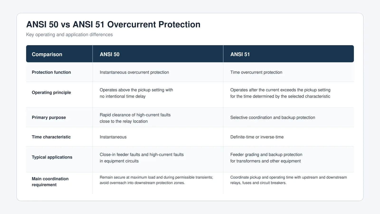
ANSI 50 prioritises high-speed fault clearance, while ANSI 51 provides selectivity and coordinated backup protection. The two functions are commonly used together to achieve an appropriate balance between operating speed and continuity of supply.
The effective reach of an ANSI 50 element depends on fault-current distribution, system impedance, source configuration and the selected pickup setting. Unlike distance-protection zones, it should not be defined as a fixed percentage of line length without a system-specific study.
4. How Does ANSI 50/51 Differ from Earth-Fault Overcurrent Protection?
ANSI 50/51 generally refers to phase-overcurrent protection. It is primarily used to detect phase-to-phase faults, three-phase faults and abnormal phase currents.
Earth faults are commonly detected by dedicated neutral or residual overcurrent elements, including:
- ANSI 50N/51N — Instantaneous and time neutral overcurrent protection;
- ANSI 50G/51G — Instantaneous and time ground overcurrent protection;
- ANSI 67N — Directional neutral or earth-fault overcurrent protection.
ANSI 50/51 should not, therefore, be treated as a general designation for every type of earth-fault protection. Earth-fault detection capability depends on the relay measurement method, CT connections, the method used to derive or measure residual current, and the system neutral-earthing arrangement.
The suffix conventions used by individual relay manufacturers may vary. The applicable relay manual and project protection philosophy should therefore be consulted when interpreting 50N, 51N, 50G and 51G designations.
5. Common Overcurrent Operating Characteristics
5.1 Instantaneous Overcurrent
- An instantaneous overcurrent element operates when the measured current exceeds the pickup setting, with no intentional time delay. It is suitable for the rapid clearance of high-current faults close to the protection location.
- Although the relay element has no intentional delay, the total fault-clearance time still includes relay processing time, output contact operating time and circuit-breaker opening time.
5.2 Definite-Time Overcurrent
- A definite-time overcurrent element operates after a preset delay once the measured current exceeds the pickup value. The operating time remains substantially constant regardless of how far the current exceeds the pickup setting.
- Definite-time protection allows straightforward time grading between successive protection devices.
5.3 Inverse-Time Overcurrent
With inverse-time overcurrent protection, the operating time decreases as the fault current increases. Currents close to the pickup value result in longer operating times, while higher fault currents result in faster operation.
Common operating characteristics include:
- IEC standard inverse;
- IEC very inverse;
- IEC extremely inverse;
- IEEE moderately inverse;
- IEEE very inverse;
- IEEE extremely inverse.
The appropriate curve should be selected according to load characteristics, equipment withstand capability, available fault-current levels and coordination requirements with other protection devices.
6. Main Advantages of ANSI 50/51 Protection
Fast detection of high-magnitude phase-to-phase and three-phase faults, with coordinated operation for lower-magnitude overcurrents;
Instantaneous, definite-time and inverse-time operating characteristics;
Application as feeder primary protection or equipment backup protection;
Suitability for feeders, transformers, motors, generators and bus-coupler circuits;
Effective selective coordination between upstream and downstream protection devices;
Direct tripping of circuit breakers through switchgear control circuits;
Fault records, event records and fault-current measurements in numerical relays;
Integration with SCADA and substation automation systems through communication interfaces;
Reduced fault-clearing times and limited outage areas when properly coordinated.
7. What Should Be Considered When Setting ANSI 50/51 Protection?
Overcurrent protection settings should not be based solely on equipment rated current. Protection selection and setting calculations should consider:
- Maximum system load current;
- Equipment rated current and permissible overload capability;
- Maximum and minimum fault-current levels at relevant locations in the protected network;
- Maximum and minimum system operating configurations and their effect on available short-circuit current;
- Current-transformer ratio, accuracy class, connected burden, transient performance and saturation characteristics under high fault-current conditions, including their effects on relay measurement accuracy and operating time;
- System neutral-earthing arrangement;
- Motor starting current and starting time;
- Transformer magnetising inrush current;
- Capacitor-bank energisation inrush;
- Pickup and time coordination between upstream and downstream protection devices;
- Circuit-breaker interrupting rating and opening time;
- Coordination between primary and backup protection;
- Fault-current characteristics of inverter-based resources;
- Applicable IEC or IEEE inverse-time characteristics.
Current-transformer saturation can distort the secondary current supplied to the relay, potentially reducing the measured fault-current magnitude or delaying relay operation. CT performance should therefore be verified for the maximum prospective fault current, connected burden, required protection class and applicable transient conditions.
Properly selected settings should satisfy the required selectivity, speed, sensitivity, dependability and security. The protection must clear genuine faults promptly without operating unnecessarily during permissible overloads, equipment starting or normal switching transients.
8. Limitations of ANSI 50/51 Protection
Although ANSI 50/51 protection is simple, reliable and widely applicable, its performance depends on the magnitude of the fault current measured at the relay location.
Important limitations include:
- Insufficient sensitivity to low-magnitude faults;
- Lower available fault-current levels under minimum-generation or weak-source operating conditions;
- Possible underreach or delayed operation caused by CT saturation;
- Limited selectivity in ring or multi-source networks without directional elements;
- Difficulty detecting high-resistance faults;
- Limited effectiveness where inverter-based resources provide restricted fault-current contribution;
- Possible miscoordination when system operating configurations change significantly.
For large transformers and generators, overcurrent protection may not reliably detect all internal faults. Differential protection therefore remains the preferred primary protection for internal phase faults, while ANSI 50/51 is generally used as backup protection.
Where conventional overcurrent protection cannot provide sufficient sensitivity, speed or selectivity, additional functions such as differential protection, directional overcurrent protection, voltage-dependent overcurrent protection or communications-assisted protection should be considered.
9. Conclusion
- ANSI 50/51 overcurrent protection relays are widely applied to distribution lines, incoming and outgoing feeders, transformers, motors, generators, bus couplers, capacitor banks, reactors, and solar PV, wind-power and battery energy storage systems.
- ANSI 50 is primarily used for the rapid clearance of high-current faults close to the relay location, while ANSI 51 provides time-delayed protection, selective coordination and backup protection. In radial distribution systems, ANSI 50/51 typically serves as the primary phase-fault protection for medium-voltage feeders.
- For large transformers, generators and other critical equipment, overcurrent protection is generally used as backup to differential or other dedicated protection functions because its sensitivity may be insufficient for certain low-magnitude internal faults.
- In ring networks, double-ended systems, multi-source networks and systems containing distributed generation, directional overcurrent protection such as ANSI 67 may also be required. The final protection scheme and relay settings should be determined from the system configuration, neutral-earthing arrangement, equipment characteristics, maximum and minimum operating configurations, short-circuit study and protection coordination study.


