

GWPR350‑BD Busbar Differential Protection Relay
Product Desc
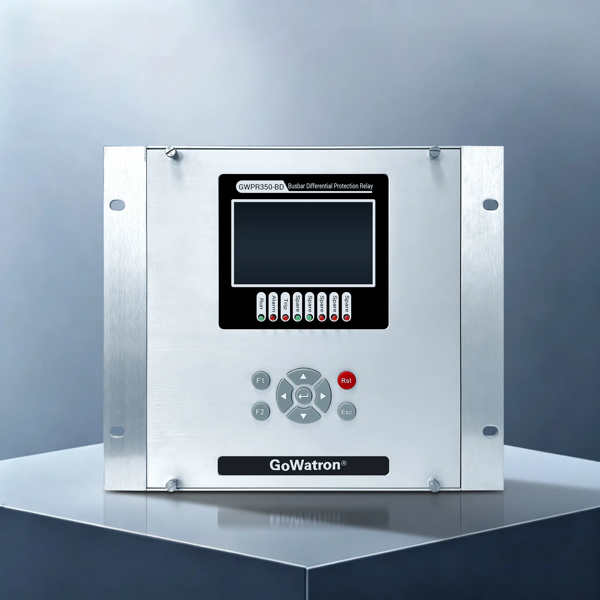
- GWPR350‑BD Busbar Differential Protection Relay is a 7‑bay numerical busbar differential protection device launched by GoWatron. Designed for 11‑33kV single‑bus non‑sectionalized unearthed neutral distribution systems, it supports up to 7 protection branches. Adopting a percentage biased differential algorithm, it integrates busbar differential protection, branch backup overcurrent protection, abnormal alarm, fault recording and multi‑interface communication. It can rapidly clear internal busbar short‑circuit faults and prevent station‑wide blackouts, delivering a reliable main‑protection solution for medium‑voltage distribution busbars.
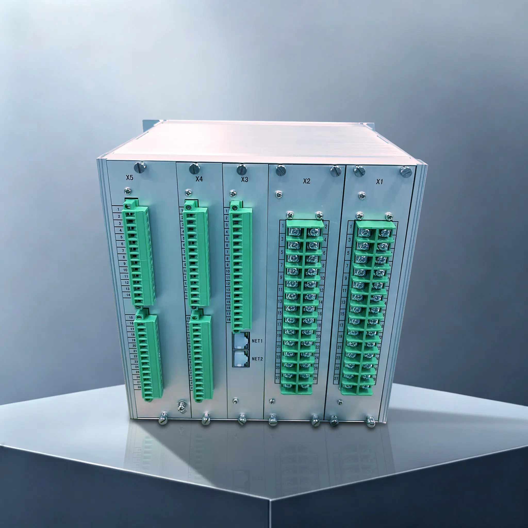
- 2‑port 10/100M adaptive Ethernet (IEC 60870‑5‑103 supported, IEC 61850 optional)
- 1 port optically‑isolated RS485 (Modbus‑RTU)
- IRIG‑B time synchronization, enabling remote signaling, remote measurement and remote control.




High precision
≤0.2%

Quick response
≤35ms

ReliableProtection
multi-protection

Quality Assurance
ISO 9001 Certified

Technical Support
24/7 Expert Support

Fast Delivery
Global Shipping

Warranty
2 Year Warranty
Product Description
- GWPR350‑BD Busbar Differential Protection Relay adopts a 32‑bit ARM Cortex‑M4 high‑performance CPU coupled with high‑precision A/D sampling chips for high‑speed processing and high sampling accuracy. Its overall operating time ≤40 ms for fast response to busbar faults.
- Built with SMT multi‑layer PCB technology, the device features standby power consumption below 10 W and has passed multiple EMC tests to ensure reliable operation under severe electromagnetic interference in industrial substations. It is equipped with a 4.3‑inch 800×480 full‑Chinese IPS color LCD with intuitive keypad operation for convenient commissioning and maintenance.
- The protection algorithm is based on the percentage biased differential principle, with built‑in CT saturation detection to prevent mal‑operation caused by CT saturation during external faults. Composite‑voltage blocking logic is implemented for differential outputs to further enhance protection reliability.
- Comprehensive recording functions cover event logs, operation records and fault recording, with non‑volatile data storage. Dual hardware watchdog circuits ensure long‑term stable operation.
- Flexible mounting options support both on‑site cabinet installation and centralized panel mounting in main control rooms to satisfy diverse project requirements. CT rated secondary current is available in 5A or 1A (1A to be specified upon order) for compatibility with various instrument transformer configurations.
Product Functions
(ANSI 87B) Busbar Differential Protection
- Based on percentage biased differential algorithm with built‑in CT saturation detection, it reliably distinguishes internal and external faults and prevents mal‑operation induced by external‑fault CT saturation. Both full‑differential and partial‑differential setting modes are available to adapt to field conditions where partial‑branch CTs are not connected to the device. It quickly isolates internal busbar short‑circuit faults.
(ANSI 87B) Two‑stage Differential Protection with Composite‑voltage Blocking
- Stage I and Stage II differential‑current protection with independently configurable setting values and time delays. The protection output is blocked under abnormal voltage conditions via composite‑voltage blocking logic to minimise mal‑operation risks.
(ANSI 50/51) Two‑stage Overcurrent Protection
- Each of the 7 branches features independent two‑stage overcurrent protection. Current setting and time delay can be configured per branch to serve as backup protection for outgoing feeders.
(ANSI 60 ) PT Circuit Failure Alarm
- Real‑time monitoring of voltage loops. Alarms are triggered with time delay upon PT circuit failure or loss of voltage; alarms auto‑reset after voltage loop restoration.
(ANSI CT‑F) CT Secondary‑circuit Failure Alarm
- CT secondary‑circuit failure detection based on differential current monitoring. Time‑delayed alarm is activated when differential current exceeds threshold. The differential protection can be blocked via control word configuration. Alarms auto‑reset upon CT circuit restoration.
Recording, Communication & Commissioning Features
- Event records, action reports, operation logs and fault recording; all data non‑volatile for post‑fault analysis.
- 21 binary inputs (wet contacts, internally powered), 22 passive relay outputs; soft‑bay control supported.
- Local LCD HMI, output‑relay test, channel verification and self‑diagnosis facilitate on‑site commissioning and maintenance.
Technical Specifications
| Item | Specifications |
| Device Model | GWPR350‑BD Busbar Differential Protection Relay |
| Operating Power Supply | AC/DC 85 to 265V; Standby power consumption ≤10W, operating power consumption ≤15W |
| CT Rated Input | 5A (1A to be specified upon order); Measuring range 0.04 ~ 20In; Per‑phase burden ≤1VA |
| PT Rated Input | AC100V; Measuring range 0.5 V ~ 120 V; Per‑phase burden ≤0.5VA |
| Protection Accuracy | Setting accuracy ≤ ±3%; Time accuracy < ±1% of set value or ±35 ms (whichever is greater); Overall operating time ≤40 ms |
| Binary Inputs | 21 binary inputs (wet contacts, internally powered) |
| Relay Outputs | 22 passive relay outputs; Rated AC250V / 8A, 1250VA, with 2500V isolation |
| Operating Environment | Operating temperature ‑10℃~+55℃; Storage ‑25℃~+70℃; Humidity 5%‑95%; Ingress protection IP50 |
| Insulation & Withstand Voltage | Insulation resistance ≥ 100 MΩ; Power‑frequency withstand voltage 2000 V for 1 min; Impulse withstand voltage 5 kV |
| EMC Performance | Passed Class A EMC tests (ESD, surge, fast transient burst, magnetic field immunity, etc.) |
| Mounting | Panel flush‑mount; cabinet local installation or main‑control‑room centralized panel mounting |
Application Scenarios
- 11‑33 kV single‑bus non‑sectionalized substations with unearthed neutral distribution systems, maximum 7 branches;
- Medium‑voltage busbar protection for captive‑power substations and factory distribution rooms in mining and industrial plants;
- Single‑bus systems inside photovoltaic, wind power and other renewable energy power stations;
- Single‑bus configurations for urban distribution switchgear and ring main units;
- New‑build and retrofit power projects supporting both local cabinet‑mounted deployment and centralized main‑control‑room panel‑mounting;
Note: This device is designed for single‑bus non‑sectionalized topologies. NOT applicable to double‑bus or single‑bus sectionalized configurations.


