33 kV Medium Voltage Switchgear: Common Types, Functional Configurations and Selection Guide
- 33 kV medium voltage switchgear is used to receive, distribute, control, protect and monitor electrical power in 33 kV distribution systems. Typical applications include industrial substations, utility distribution substations, power plants, and step-up substations for solar PV and wind farms.
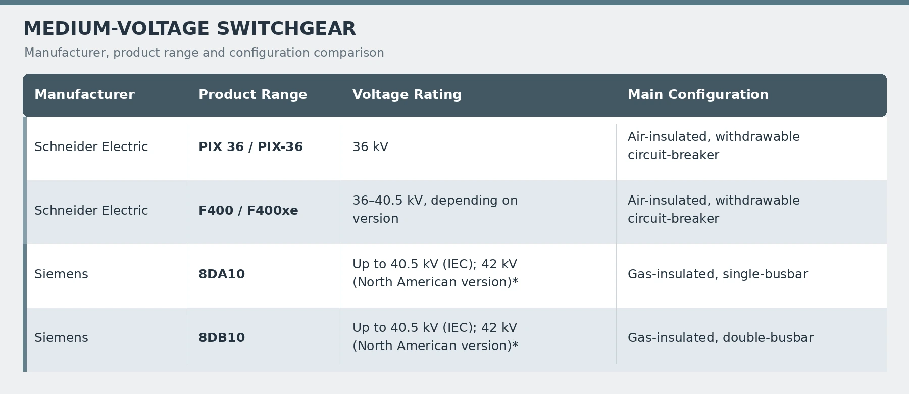
- Common types and product ranges include KYN61-40.5, XGN□-40.5, PIX 36, F400/F400xe, 8DA10 and 8DB10. These ranges differ in equipment mounting arrangements, busbar configurations, ratings and maintenance requirements. Selection should be based on system requirements and the technical documentation for the specific equipment.
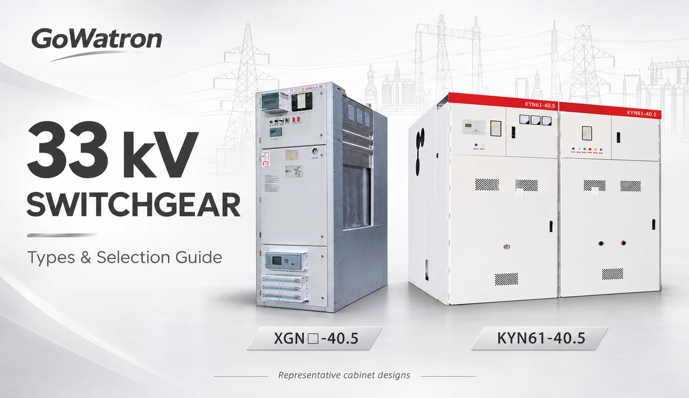
1. What Is 33 kV Medium Voltage Switchgear?
33 kV medium voltage switchgear is an assembly of switching and associated equipment intended for use in a 33 kV power system. Depending on the function of each panel, it may incorporate circuit-breakers, busbars, current transformers (CTs), voltage transformers (VTs), earthing switches, protection and control intelligent electronic devices (IEDs), and auxiliary circuits.
Its main functions include:
- Power distribution: Receiving power and supplying outgoing circuits, transformers or other equipment.
- Operational control: Switching circuits into and out of service and connecting busbar sections.
- Fault clearance: Interrupting fault current through a circuit-breaker following a trip command from the protection system.
- Measurement and monitoring: Acquiring current, voltage, power, energy and equipment status information.
- Isolation and earthing: Establishing the conditions required for maintenance in accordance with the equipment design and operating procedures.
International manufacturers generally classify switchgear for 33 kV systems as medium voltage switchgear. In Chinese engineering practice, equipment at this voltage level is also commonly described as high-voltage switchgear.
Equipment selection should be governed by its ratings, insulation level and the project specification.
2. Why Do 33 kV Systems Use 36 kV or 40.5 kV Switchgear?
The designation 33 kV normally refers to the nominal system voltage, whereas 36 kV or 40.5 kV refers to the rated voltage of the switchgear.
| Voltage Parameter | Meaning Purpose | in Selection |
| Nominal system voltage | The approximate voltage used to identify the system, such as | 33 kV Defines the system voltage class |
| Highest voltage of the system | The greatest phase-to-phase RMS operating voltage under normal conditions, considering all locations and times | Provides a basis for checking the equipment voltage rating |
| Rated voltage of the equipment | The voltage assigned to the equipment on which specified operating and performance requirements are based | Defines the equipment voltage rating |
| Rated insulation level | The specified power-frequency and impulse withstand capabilities | Provides a basis for insulation coordination |
- The highest voltage of the system excludes transient overvoltages and abnormal temporary voltage variations. These are addressed separately through insulation coordination.
- The term highest voltage for equipment, commonly designated \(U_m\), relates to equipment insulation and other voltage-dependent characteristics. It is distinct from the highest voltage of the system.
- For 33 kV projects using IEC voltage ratings, 36 kV switchgear is a common option. Projects using equipment manufactured to Chinese specifications may also consider 40.5 kV switchgear.
- The rated voltage of the equipment must be at least equal to the highest voltage of the system. Selection must also address rated frequency, insulation level, short-circuit capability, system earthing and site conditions.
3. Common Types of 33 kV Medium Voltage Switchgear
3.1 KYN61-40.5 Metal-Clad Withdrawable Switchgear
KYN61-40.5 is a common type of indoor metal-enclosed switchgear used in Chinese 35 kV-class distribution projects. It may also be considered for 33 kV applications, subject to verification against the project requirements.
Typical features include:
- A withdrawable circuit-breaker truck.
- A vacuum circuit-breaker in typical configurations.
- Separate compartments for busbars, the circuit-breaker, cable connections and low-voltage control equipment, depending on the design.
- Panel configurations for incomers, outgoing feeders, bus-section circuit-breakers and VTs.
- Mechanical and electrical interlocks appropriate to the equipment arrangement.
Some products are designated KYN61-40.5(Z), where “Z” generally indicates a vacuum circuit-breaker configuration. The exact designation should be confirmed in the manufacturer’s documentation.
Dimensions, circuit-breakers, ratings, interlocking arrangements and type-test coverage may vary between manufacturers. Compatibility must therefore be verified for extensions and replacements.
- The arrangement of circuit-breakers and disconnecting devices.
- How the isolating position is established and verified.
- Earthing switch provision and operating conditions.
- The extent of the outage required for maintenance.
- Cable connection and maintenance access.
3.3 Relevant International Product Ranges
4. Typical Functional Panels in 33 kV Medium Voltage Switchgear
A switchgear type designation identifies the equipment family. Terms such as incomer panel, outgoing feeder panel and bus-section panel identify the function of an individual panel within the system.
The same product range can provide several functional panel configurations.
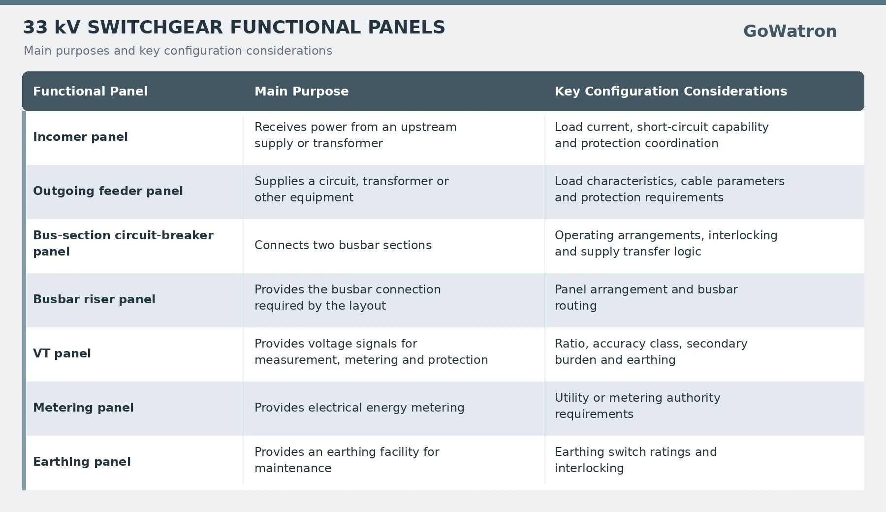
Functions may be combined or provided in dedicated panels, depending on the single-line diagram, metering requirements and maintenance arrangements.
5. How to Select 33 kV Medium Voltage Switchgear
5.1 Establish the Rated Voltage and Insulation Level
- First establish the nominal system voltage and the highest voltage of the system. Then verify the equipment rated voltage, rated power-frequency withstand voltage and rated lightning impulse withstand voltage.
- Insulation coordination should also consider system earthing, overvoltages, surge arrester protection and installation conditions. These requirements determine whether a particular 36 kV or 40.5 kV design is suitable.
5.2 Determine the Rated Normal Current
The rated normal current of each main circuit should accommodate the maximum continuous load, taking account of supply transfer duties, overload requirements and future expansion.
For a three-phase system, the load current can be estimated from apparent power:
\[ I=\frac{S}{\sqrt{3}\,U} \]
where:
- \(I\) is the line current, in A;
- \(S\) is the total three-phase apparent power, in VA;
- \(U\) is the line-to-line voltage, in V.
For example, a 33 kV circuit carrying 40 MVA has an estimated current of:
\[ I=\frac{40\times10^6}{\sqrt{3}\times33\times10^3} \approx700\ \text{A} \]
The selected equipment rating must account for this load current together with ambient temperature, altitude, temperature-rise limits and the required operating margin.
Busbars, incomers and outgoing feeders may have different current requirements and should be assessed separately.
Note: The calculated 700 A is a load estimate, not an equipment ordering rating.
5.3 Determine Short-Circuit Breaking and Withstand Requirements
The following ratings should be checked against the short-circuit study for the installation:
- Circuit-breaker rated short-circuit breaking current.
- Circuit-breaker rated short-circuit making current.
- Switchgear rated short-time withstand current and rated duration of short-circuit.
- Rated peak withstand current.
- Applicable earthing switch ratings.
A short-time withstand rating of 31.5 kA for 3 s describes the ability to withstand the specified current for the stated duration. Circuit-breaker breaking capability must be verified separately.
The rated duration of short-circuit should be coordinated with the required fault clearance time, including backup protection clearance where applicable.
5.4 Verify Internal Arc Classification
- Where internal arc classification is specified, verify the complete IAC designation, including accessibility type, classified sides, test current and arc duration.
- For example, an illustrative designation of IAC A FLR 25 kA 1 s indicates:
| Designation | Meaning |
| IAC | Internal arc classification |
| A | Access restricted to authorised personnel |
| F | Classified front side |
| L | Classified lateral sides |
| R | Classified rear side |
| 25 kA | Specified internal arc test current |
| 1 s | Specified arc duration |
- Accessibility Type A identifies assessment conditions associated with access by authorised personnel. It is not a ranking of safety or an indication that Type A is the “safest” classification.
- Accessibility Type B concerns unrestricted access, including access by the general public.
- Type C relates to equipment installed out of reach above an area accessible to the public. It involves a different installation and assessment context; its applicability should be checked against the relevant standard and edition.
- The installation must comply with the manufacturer’s specified conditions, including pressure relief arrangements, exhaust ducts, rear clearances and switchroom layout.
- Note: IAC performance applies under specified test and installation conditions. Correct protection, installation and maintenance remain essential.
5.5 Define Maintenance Access and Service Continuity Requirements
- Selection should establish which circuits must be taken out of service when a compartment or primary component is accessed, and which parts may remain energised.
- The loss of service continuity (LSC) category describes the extent to which other compartments and functional units may remain energised when an accessible high-voltage compartment is opened under the prescribed conditions.
For a typical single-busbar arrangement:
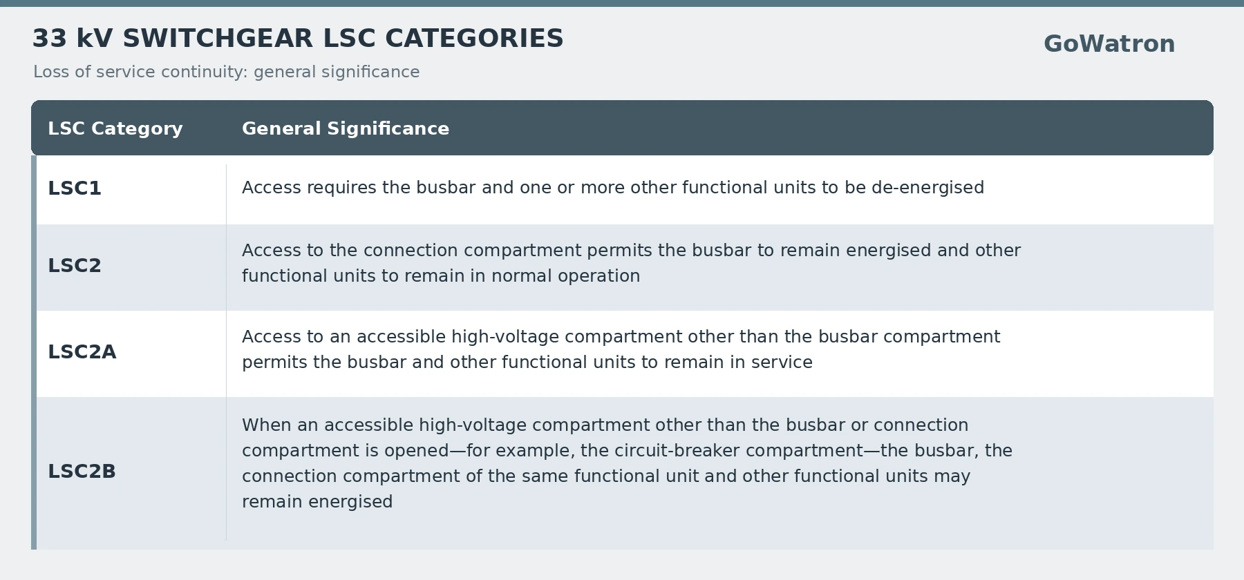
- For example, an LSC2B design may allow the isolated circuit-breaker compartment to be opened for maintenance while the busbar, other functional units and the cable connection compartment of the same functional unit remain energised.
- Access to the cable connection compartment is a separate operation requiring the relevant isolation, verification of absence of voltage and earthing procedures.
- The LSC category, partition class, compartment design and manufacturer’s operating instructions should be considered together. For staged expansion, busbar interfaces, extension direction and the required outage should also be checked.
- Note: LSC describes service continuity during specified access operations. Internal arc performance is covered separately by IAC classification.
5.6 Check Environmental and Installation Conditions
The assessment should include:
- Altitude and ambient temperature.
- Humidity, condensation and pollution.
- Salt exposure, corrosion and seismic requirements.
- Indoor or outdoor installation.
- Cable trenches, foundations and floor loading.
- Cable bending radii and termination space.
- Operating, transport and maintenance access.
For high-altitude installations, the manufacturer should confirm any required insulation corrections and current derating. Where high humidity or significant temperature variations are expected, ventilation, heating and dehumidification should be considered to control condensation.
6. Protection Functions for 33 kV Medium Voltage Switchgear
Protection requirements depend on the connected equipment, system earthing, operating arrangements and coordination with upstream and downstream protection.
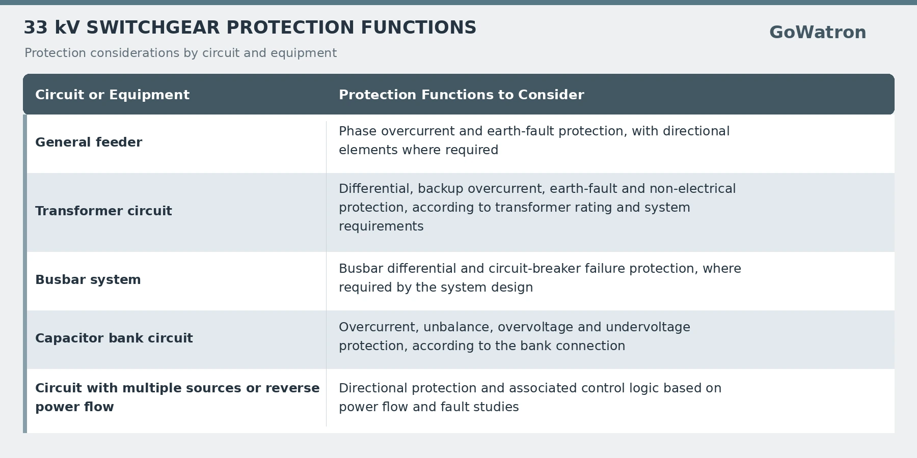
- Earth-fault protection, also referred to as ground-fault protection, should use measuring quantities and operating principles appropriate to the system earthing arrangement.
- Protection IED current and voltage inputs must match the CT and VT secondary ratings. Protection CTs should also meet the accuracy and transient performance requirements of the selected protection scheme.
- The final protection configuration should be established through system studies and protection coordination.
7. Connecting 33 kV Medium Voltage Switchgear to SCADA
Switchgear can be connected to a SCADA system through protection and control IEDs, dedicated measurement devices or communication gateways.
| Information or Function | Typical Content |
| Measurements | Current, voltage, active power, reactive power and frequency |
| Status indications | Circuit-breaker position, earthing switch position and equipment alarms |
| Event records | Protection starts, protection operations and status changes |
| Remote control | Circuit-breaker opening and closing, subject to permissions and interlocks |
| Energy data | Active and reactive energy |
- Available functions depend on device capabilities, secondary wiring, communication protocols and the agreed signal list.
- Remote control must be coordinated with local/remote selection, operating permissions and equipment interlocks.
- Note: Ethernet provides networking functions, while RS-485 specifies electrical interface characteristics. Supported application protocols and remote control functions must be confirmed separately.
8. Common Selection Mistakes
8.1 Specifying Only the System Voltage
- An enquiry or technical specification should define equipment rated voltage, rated normal current, short-circuit ratings, insulation level, frequency and installation conditions.
- A complete specification enables quotations to be compared on a consistent technical basis.
8.2 Assuming Identical Type Designations Mean Interchangeability
- Products with the same type designation may use different circuit-breakers, busbar interfaces, panel dimensions and interlocking arrangements.
- Extensions and replacements require verification of the actual interfaces, ratings and compatibility.
8.3 Treating a Switch-Disconnector Panel as a Circuit-Breaker Panel
- Switch-disconnectors and circuit-breakers have different switching duties and breaking capabilities.
- For a ring main unit arrangement, identify whether each way incorporates a switch-disconnector, a switch-fuse combination or a circuit-breaker, and confirm how faults will be cleared.
8.4 Assuming a Vacuum Circuit-Breaker Means Vacuum Insulation Throughout the Panel
- Vacuum is used inside the circuit-breaker interrupters to interrupt current. The main insulation of the switchgear assembly uses a separate insulation system.
- For example, PIX 36 and F400 are air-insulated product ranges, while conventional Siemens 8DA10/8DB10 configurations use SF₆ gas for primary insulation and vacuum interrupters for current interruption.
- Specify the assembly insulation system and the circuit-breaker interrupting medium separately, using the technical data for the selected product version.
8.5 Comparing Panel Prices Without Aligning the Technical Scope
- Price comparisons should use a consistent scope covering circuit-breakers, instrument transformers, protection IEDs, test documentation, internal arc performance, spare parts and maintenance requirements.


