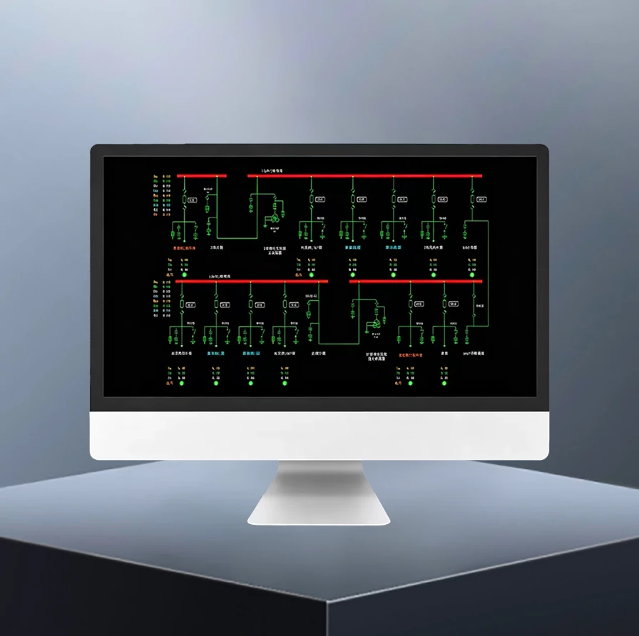
GWSC‑SUB Substation Automation & SCADA System
Product Desc
- The GWSC-SUB Substation SCADA System is designed for international power projects and fully complies with IEC standards. It supports 132kV, 110kV, 66kV, 33kV, 22kV and 11kV substations, suitable for both new installations and substation modernization projects, enabling unattended or minimally attended operation.
- The system provides complete Four-Remote functions (remote measurement, signalling, control and adjustment), with optional video surveillance integration. Key functions include SOE recording, fault playback, disturbance analysis, alarm management and operation reporting. Integrated with the GWPC-FPS Five-Protection System, it supports IEC 61850 interlocking logic and seamless integration of equipment monitoring, environmental monitoring, security and fire-alarm systems.
- A four-tier architecture (station control, communication, bay and process levels) ensures reliable and independent operation. Bay-level devices maintain protection, control and tripping functions even during communication failures.




High Precision
≤0.2%

Quick Response
≤5s

Five Remotes
YC / YX / YK / YT / YS

Reliable Protection
99.99% Availability

Quality Assurance
IEC Full Compliance

Technical Support
≥10 Years Spare Parts

Warranty
2 Year Warranty
System Composition
Station‑control Level
- The station‑control level serves as the core monitoring and management hub of the full‑station SCADA system. Its main functions include full‑station data aggregation and storage, human‑machine interaction, alarm handling, operation reporting, protection relay setting management, five‑protection logic computation and dispatching‑interface communication. The station‑control level performs only monitoring, management and validation functions and does not participate in any local protection‑tripping logic. All protective actions are executed independently by bay‑level devices.
- System cybersecurity is designed in accordance with IEC 62443‑3‑3. It supports RBAC (Role‑Based Access Control), operation‑audit logging (compliant with IEEE 1686 for IED cybersecurity), and encrypted communication (TLS 1.3 / SSH) to satisfy cybersecurity compliance requirements for overseas power utilities.
- GWPC‑SCADA Station Control & SCADA Panel: Deployed in hot‑standby redundancy. Runs core SCADA services with real‑time and relational databases for full‑station data acquisition, storage, logic processing and event logging to ensure continuous system operation.
- GWPC‑OWS Operator & Engineer Workstation Panel: Human‑machine‑interface terminal for single‑line‑diagram supervision, remote control operation, alarm acknowledgement, system parameter configuration, protection relay setting and on‑site fault commissioning.
- GWPC‑FPS Five‑Protection System Panel: Implements standardised anti‑mal‑operation logic complying with IEC 61850 logical interlocking requirements to prevent electrical mal‑operations. All remote commands are issued only after successful five‑protection logic validation.
Communication Level
- The communication level acts as the data‑transport backbone, facilitating data exchange between station‑control level, bay level and third‑party auxiliary equipment. It performs protocol conversion, data forwarding and system‑wide time synchronisation. No protection or control logic is implemented at this level.
- Supported mainstream communication protocols: IEC 61850, DNP3.0, IEC 60870‑5‑104, Modbus, with backward compatibility with IEC 60870‑5‑101 / 103.
- GWPC‑RTU Remote Terminal Unit Communication Panel: Equipped with industrial‑grade gateway supporting the above‑mentioned international power‑system protocols, bidirectional protocol translation and transparent data transmission. It uploads four‑remote data, equipment status, fault alarms and SOE records to overseas dispatch centres or remote control centres, and forwards received remote‑control, remote‑adjustment and setting‑query commands to corresponding bay‑level IEDs for remote grid‑connected substation management.
- GWPC‑TS Time Synchronization Panel (GPS/Bei‑Dou): Integrated GPS / PTP (Precision Time Protocol, IEEE 1588‑v2) dual time‑reference modules. Communication‑layer switches support PTP transparent‑clock or boundary‑clock modes, achieving IED‑level PTP time‑synchronisation accuracy ≤ 1 μs. It delivers unified high‑precision timing for all station‑control‑level and bay‑level IEDs to guarantee consistent timestamps for events, fault sequences and sampled measurements, satisfying overseas fault‑traceability and acceptance criteria.
- Auxiliary communication hardware: Dual‑redundant industrial Ethernet switches, optical‑electrical converters, network surge‑protection devices, dedicated optical fibres and shielded twisted‑pair cables, implementing a redundant full‑station communication network free of single‑point‑of‑failure risks.
- Core communication‑level functions: Forward bay‑level operational data and alarms to the station‑control level; relay validated station‑control‑level commands down to bay‑level devices; interface with third‑party auxiliary subsystems. Network faults only affect remote supervision and do not interfere with bay‑level local protection and tripping.
Bay Level
- The bay level implements local protection, measurement and control for each electrical bay. It features full local autonomy: protection actions, data acquisition and equipment control continue operating upon loss of back‑end or communication links to safeguard primary‑equipment safety. Hardware is split between central‑room cabinet‑mounted equipment and switchgear‑mounted field devices.
Central‑room Cabinet‑mounted Equipment
- GWPC‑TP Transformer Protection Panel: Configured with protection relays implementing transformer differential, HV/LV back‑up and non‑electrical protection functions.
- GWPC‑MTC Main Transformer Measurement & Control Panel: IED for transformer analogue acquisition, status monitoring and on‑load tap‑changer remote adjustment. Dual‑redundant protection relays are optional for 132 kV / 110 kV main transformers per project requirements.
- GWPC‑LP Line Protection Panel: For 132 kV, 110 kV, 66 kV line bays. Protection relays provide differential, distance and over‑current protection functions.
- GWPC‑LMC Line Measurement & Control Panel: IED for line analogue measurement, status supervision and remote control.
- GWPC‑CP Capacitor Protection Panel: For shunt‑capacitor banks. Protection relays realise differential, over‑voltage, under‑voltage, harmonic‑over‑current and neutral‑point‑unbalance protection.
- GWPC‑CMC Capacitor Bank Measurement & Control Panel: IED for capacitor‑bay measurement and control ensuring stable reactive‑power‑compensation operation.
- GWPC‑BVM Bus Voltage Measurement & Control Panel: PT‑signal acquisition, bus‑voltage paralleling / switching and over‑/under‑voltage alarming. Supports single‑phase‑to‑earth fault detection (zero‑sequence voltage / zero‑sequence current monitoring) for stable bus‑voltage supervision.
- GWPC‑CCM Common Control & Measurement Panel: Collects auxiliary signals from station‑service transformers, DC systems, chamber environment, security and water‑leakage sensors and uploads aggregated data to the SCADA host.
- GWPC‑DFR Digital Fault Recorder Panel: Fault‑recorder captures analogue and binary status pre‑fault and post‑fault time‑series data. Oscillography files comply with IEC 60255‑24 (COMTRADE) format and are compatible with mainstream fault‑analysis software, providing evidence for fault investigation and acceptance tests.
- GWPC‑UFLS Under‑Frequency & Under‑Voltage Load‑Shedding Panel (Optional): Sheds loads hierarchically according to pre‑set logic during frequency‑or‑voltage excursions to stabilise grid parameters and enhance regional‑grid robustness.
Switchgear‑mounted Bay‑level Devices (33 kV, 22 kV, 11 kV)
- Medium‑and‑low‑voltage switchgear utilises field‑mounted devices without central‑room cabinets for simplified overseas site construction:
- Integrated protection‑control IEDs covering feeders, station‑service transformers, capacitor banks and motor loads;
- Multi‑function power meters for local measurement of current, voltage, power, energy, and harmonics;
- Switchgear intelligent control units for breaker status indication, local open/close operation, temperature‑humidity control and live‑line indication;
- Primary‑equipment online‑monitoring units: wireless temperature sensors and partial‑discharge monitors;
- Arc‑fault‑protection relays for fast internal‑arc fault clearing.
Process Level
- The process level constitutes the field‑acquisition layer. It implements no protection‑tripping or control‑output logic and only performs raw‑signal acquisition and digitisation. Equipment includes current transformers (CT), voltage transformers (PT), merging units (MU), primary‑equipment auxiliary contacts and field‑monitoring sensors, supplying raw measurements to bay‑level and station‑control‑level equipment.
AC‑DC Power‑supply System
- Provides stable operating and tripping power for station‑control‑level, communication‑level and bay‑level monitoring, protection‑relay and communication hardware, forming the foundation of secondary‑system reliability.
- GWPS‑DC DC Power‑supply Cabinet: Charging modules, battery strings, insulation‑monitoring and battery‑monitoring units supply uninterrupted DC power for protection relays, control circuits and tripping loops.
- GWPS‑AC AC Distribution Cabinet: Secondary‑system AC power‑distribution for servers, workstations, communication gear, five‑protection hardware and chamber auxiliary equipment.
Auxiliary‑Monitoring Sub‑system (Optional)
- Modular expandable integration of temperature‑humidity, water‑leakage, toxic‑gas, access‑control, video‑surveillance and fire‑alarm signals. Alarms and linkage events are transmitted via the communication level to the GWPC‑SCADA Station Control & SCADA Panel.
System Architecture (Four‑tier Strict Partition)
- Process Level: CT / PT instrument transformers, merging units (MU), field sensors, primary‑equipment auxiliary contacts. Performs only raw‑signal acquisition and digitisation; no protection‑tripping or control‑output logic.
- Bay Level: Protection relays, measurement‑control IEDs, GWPC‑DFR Digital Fault Recorder Panel. Executes local protection, measurement and control; operates autonomously during communication outages.
- Communication Level: GWPC‑RTU Remote Terminal Unit Communication Panel, GWPC‑TS Time Synchronization Panel (GPS/Bei‑Dou), switches, gateways, optical‑electrical converters. Only data forwarding, time‑synchronisation and protocol conversion; no protection logic.
- Station‑control Level: GWPC‑SCADA Station Control & SCADA Panel, GWPC‑OWS Operator & Engineer Workstation Panel, GWPC‑FPS Five‑Protection System Panel. Centralised supervision, human‑machine operation, five‑protection validation, report generation and dispatching‑interface interaction.
- Software architecture: Operating system – real‑time / relational hybrid database – communication middleware – application modules. Web‑browser‑based access is supported; no dedicated client installation is required.
Application Scenarios
- Overseas Utility‑owned Substations: 132 kV / 110 kV / 66 kV / 33 kV / 22 kV / 11 kV grid substations and switchyards for unattended operation interfaced with utility dispatch centres.
- Overseas Industrial Captive Substations: Power supply for mines, metallurgical plants, chemical complexes and large‑scale manufacturing facilities.
- Overseas Infrastructure Substations: Power systems for railways, ports, airports and large commercial complexes.
- Retrofit of Legacy Overseas Substations: Re‑use of existing primary equipment with full‑set SCADA secondary‑system deployment for digital upgrade.
FAT / SAT Acceptance Criteria
- Factory Acceptance Test (FAT) shall be performed prior to shipment in compliance with IEC 61850‑10 (conformance testing). Site Acceptance Test (SAT) shall be executed after field installation complying with IEC 60870‑5‑6 (telecontrol conformance testing). Complete test reports and commissioning records shall be delivered to satisfy overseas‑owner quality requirements.
Long‑term Operation & Maintenance Commitment
- Core hardware (servers, remote‑terminal‑unit gateways, Ethernet switches) adopts globally‑recognized industrial‑grade brands. A minimum 10‑year spare‑parts supply cycle is guaranteed to satisfy full‑lifecycle‑operation‑and‑maintenance requirements for the project.


