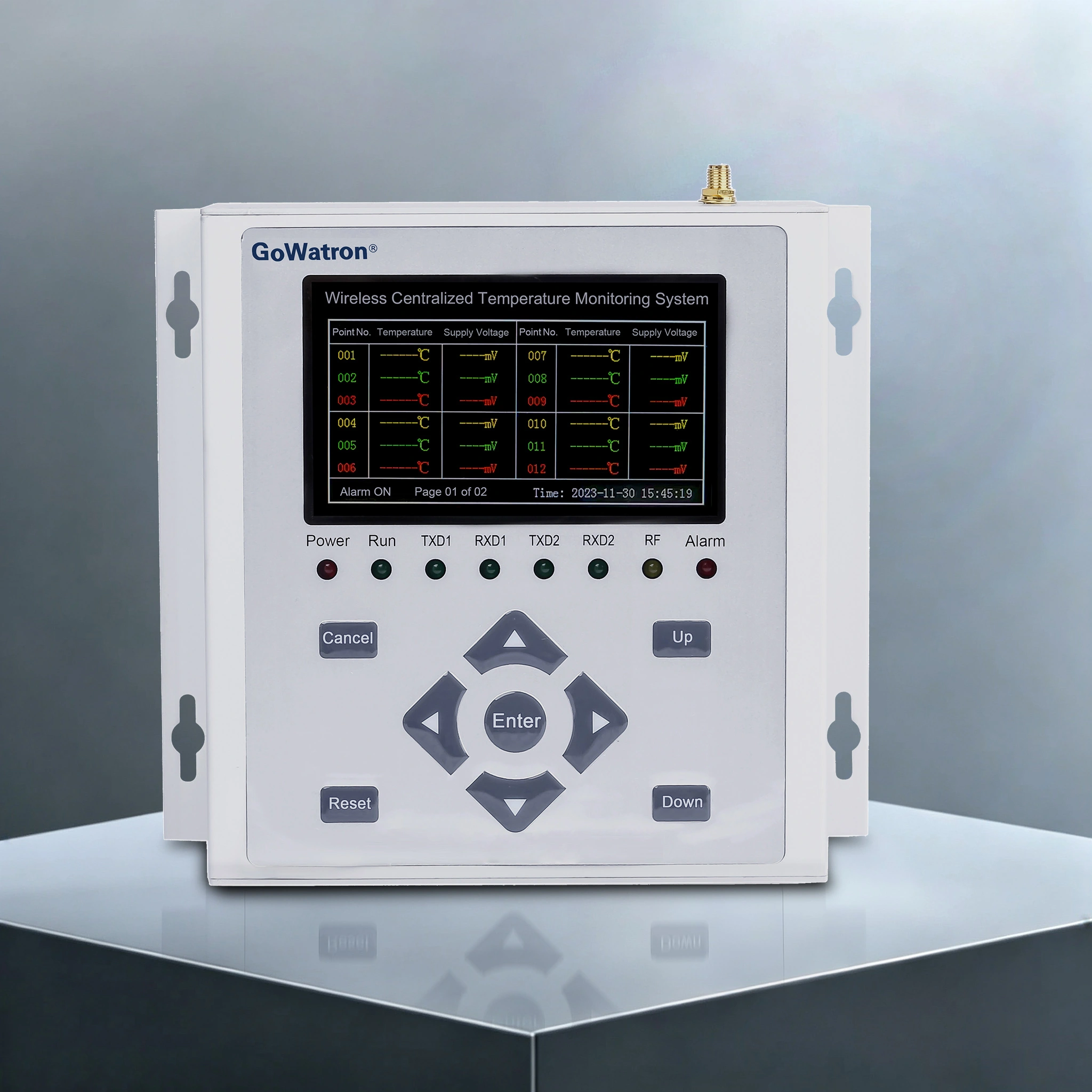
GWWT-MS Wireless Temperature Monitoring System
Product Desc
- The GWWT-MS Wireless Temperature Monitoring System is an online real-time temperature monitoring solution tailored for power distribution equipment. It is specially developed for online temperature monitoring of heat-generating nodes in high-voltage and low-voltage electrical equipment, solving the temperature detection challenges of hard-to-access high-voltage connection points (e.g., switchgears, busbar joints, and cable terminations) where wired monitoring solutions are impractical.
- Replacing traditional manual infrared temperature inspection, the system provides 24/7 online overheating pre-alarm monitoring. It fundamentally eliminates the inherent drawbacks of conventional manual inspection, including measurement delay, monitoring blind spots, and the inability to conduct real-time surveillance on high-risk heat-generating points.
- The system deploys wireless temperature sensors at critical heat-prone positions of power equipment to acquire real-time temperature data, which is wirelessly transmitted to temperature measurement gateways and the monitoring backend platform. It supports high-precision monitoring of equipment temperature fluctuations, automatic identification of abnormal temperature rises and overtemperature faults, and triggers real-time pop-up prompts as well as audible and visual alarms. This enables early detection, early warning and early troubleshooting of equipment overheating hazards.




Self‑powered
CT‑powered

Wide Temp Range
‑40℃~+125℃

Stable RF Link
LoRa long‑range

Quality Assurance
ISO 9001 Certified

Technical Support
24/7 Expert Support

Fast Delivery
Global Shipping

Warranty
2 Year Warranty
I. System Composition and Three-Tier Architecture
- The system adopts a standard three-layer architecture consisting of a perception layer, a transmission layer and an application layer, realizing full-process intelligent temperature data collection, transmission, analysis and early warning.
1. Perception Layer: Wireless Temperature Sensors
- Wireless temperature sensors are installed on heat-generating components of primary high-voltage equipment, including busbar connections, circuit breaker contacts, cable terminations, disconnector contacts, and transformer terminals. Operating at high-voltage potential, the sensors collect real-time temperature data of contact points and transmit data via wireless signals. Two mainstream types are available for different operating scenarios:
- Active Battery-Powered Sensors: Powered by built-in lithium batteries, these sensors operate independently of circuit load current and are applicable to light-load or no-load equipment scenarios. Offering a service life of 5–8 years, they require a power outage for battery replacement.
- Passive CT Energy-Harvesting Sensors: Powered by induced current harvested from busbar operating current through miniature current transformers (CTs), these sensors require no batteries and achieve maintenance-free operation. As the mainstream solution for engineering applications, they require a minimum startup current of 5–8 A and cannot operate stably when the primary circuit current is below this threshold.
2. Transmission Layer: Aggregation Gateway (Receiver)
- The aggregation gateway is installed in the secondary compartment or control room (low-voltage side) of switchgears. It receives wireless data signals from multiple temperature sensors synchronously and uploads temperature data to the local host computer or cloud platform through multiple communication modes including RS485, Ethernet, 4G and NB-IoT.
- The sensor-gateway communication adopts 433 MHz and LoRa mainstream protocols, featuring strong penetration performance for metal enclosures and excellent electromagnetic interference resistance. Zigbee protocol is also adopted in partial application scenarios.
3. Application Layer: Monitoring Platform (Local Host / Backend Software / Cloud Platform)
The monitoring platform realizes visualized and intelligent management of equipment temperature data, with core functions as follows:
- Real-time visualization of temperature readings and RSSI (Received Signal Strength Indication)
- Temperature trend curve generation, historical data storage and automatic report generation
- Multi-level threshold alarm mechanism for overtemperature and excessive temperature rise rate, supporting audible and visual alarms, desktop pop-up notifications, SMS alerts and mobile APP push reminders
- Standard interface for docking with SCADA and power management systems to realize integrated operation and maintenance of power distribution equipment
II. Core Operating Principle
- Wireless temperature sensors are installed in direct thermal contact with heat-generating electrical connection points to collect real-time temperature data. The sensors are deployed on the high-voltage primary side, while the aggregation gateway is arranged on the low-voltage secondary side. Communication is realized solely via wireless RF signals between the two sides with no electrical connection, achieving complete galvanic isolation and effectively preventing high-voltage surge from invading the secondary control circuit. The gateway aggregates and sorts the collected temperature data, and uploads valid data to the backend platform, which implements data analysis, storage, fault judgment and alarm output functions.
III. Typical Application Points
- High-voltage switchgears: Fixed and arc contacts of circuit breakers, busbar connection bolts, cable terminations, earthing switches
- Ring main units, compact substations and low-voltage high-current cabinets: Copper busbar joints and connection contacts
- Outdoor power equipment: Outdoor disconnectors, insulator clamps, overhead line connection fittings
- Power transformation equipment: Transformer bushings, terminal connection blocks, enclosed busbar joints
IV. Key Advantages
- No on-site wiring required: No secondary wiring construction on the high-voltage side; minimal renovation workload for existing equipment; live-line installation is supported for partial passive CT sensor models
- High safety reliability: Built-in high-voltage galvanic isolation design, effectively isolating high-voltage risks, especially suitable for enclosed switchgear internal monitoring scenarios
- 24/7 uninterrupted monitoring: Real-time online surveillance effectively detects potential overheating hazards caused by poor contact, loose connections and aging accessories, preventing equipment burnout and electrical fire accidents
- Flexible scalability: The number of monitoring points can be expanded freely according to demand, fully adaptable to unmanned substations and various power distribution cabinet scenarios
- Low maintenance cost: Passive CT energy-harvesting sensors achieve battery-free and maintenance-free operation, eliminating frequent battery replacement and subsequent maintenance work
V. Technical Limitations
- Passive CT energy-harvesting sensors cannot work normally when the primary circuit current is lower than the startup threshold, so they are not applicable to long-term no-load circuit scenarios
- Metal enclosures and steel structures will attenuate wireless signals; reasonable gateway layout and signal coverage planning are required during on-site engineering construction
- Active battery-powered sensors have a fixed battery service life, and battery replacement requires equipment power outage
- The installation quality of sensors directly affects measurement accuracy; sensors must be closely attached to the measured metal surface to ensure effective thermal conduction
VI. Key Technical Parameters (Reference)
| Parameter | Specification |
| Temperature Measurement Range | –40 °C to +125 °C / +150 °C (depending on sensor model) |
| Temperature Measurement Accuracy | ±0.5 °C to ±1 °C |
| Wireless Frequency Band | 433 MHz / LoRa |
| CT Energy-Harvesting Startup Current | 5 A – 8 A |
| Data Reporting Interval | Configurable (10 s to several minutes) |
| Ingress Protection Rating | IP65 – IP68 |
VII. Selection Recommendations
- For circuits operating continuously at high current, prioritize the CT‑powered solution with dual‑backup of supercapacitor and compact battery, to eliminate dead zones under light‑load conditions.
- For spare bays and no‑load circuits, adopt battery‑powered sensors with event‑driven reporting to extend battery life.
- For dense monitoring within a single cabinet, 433 MHz is preferred. For large‑scale distributed monitoring across multiple floors or cable tunnels, LoRa is preferred.
- Gateways shall be deployed to minimize communication obstructions. One data concentrator shall be configured for every 3–5 high‑voltage cabinets.
- For in‑cabinet sensors, key verification shall focus on flame‑retardant performance and power‑frequency withstand voltage. Overly high IP protection ratings shall not be specified.


