Distance Protection Relays (ANSI 21): Working Principle, Functions and Setting Calculations
- Distance protection relays (ANSI 21) use fault-loop voltage and current phasors to calculate the apparent impedance seen from the relay location. They determine whether a fault lies within a protection zone by applying directional criteria, impedance operating characteristics and time coordination.
For a uniform line under ideal conditions, such as a bolted fault, the measured impedance is approximately proportional to the line length between the relay location and the fault. Distance protection therefore uses impedance to assess the electrical distance to a fault and to selectively isolate the faulted line.
1. Working Principle of Distance Protection Relays (ANSI 21)
1.1 Measuring Fault-Loop Apparent Impedance
The basic relationship used in distance protection is:
\[ \underline Z_m= \frac{\underline U_{\mathrm{loop}}} {\underline I_{\mathrm{loop}}} \]
where:
- \(\underline Z_m\) is the measured fault-loop impedance, in Ω;
- \(\underline U_{\mathrm{loop}}\) is the corresponding fault-loop voltage phasor;
- \(\underline I_{\mathrm{loop}}\) is the corresponding fault-loop current phasor.
The measured impedance is a phasor ratio containing resistance, reactance and phase-angle information. It is not simply the ratio of voltage and current magnitudes.
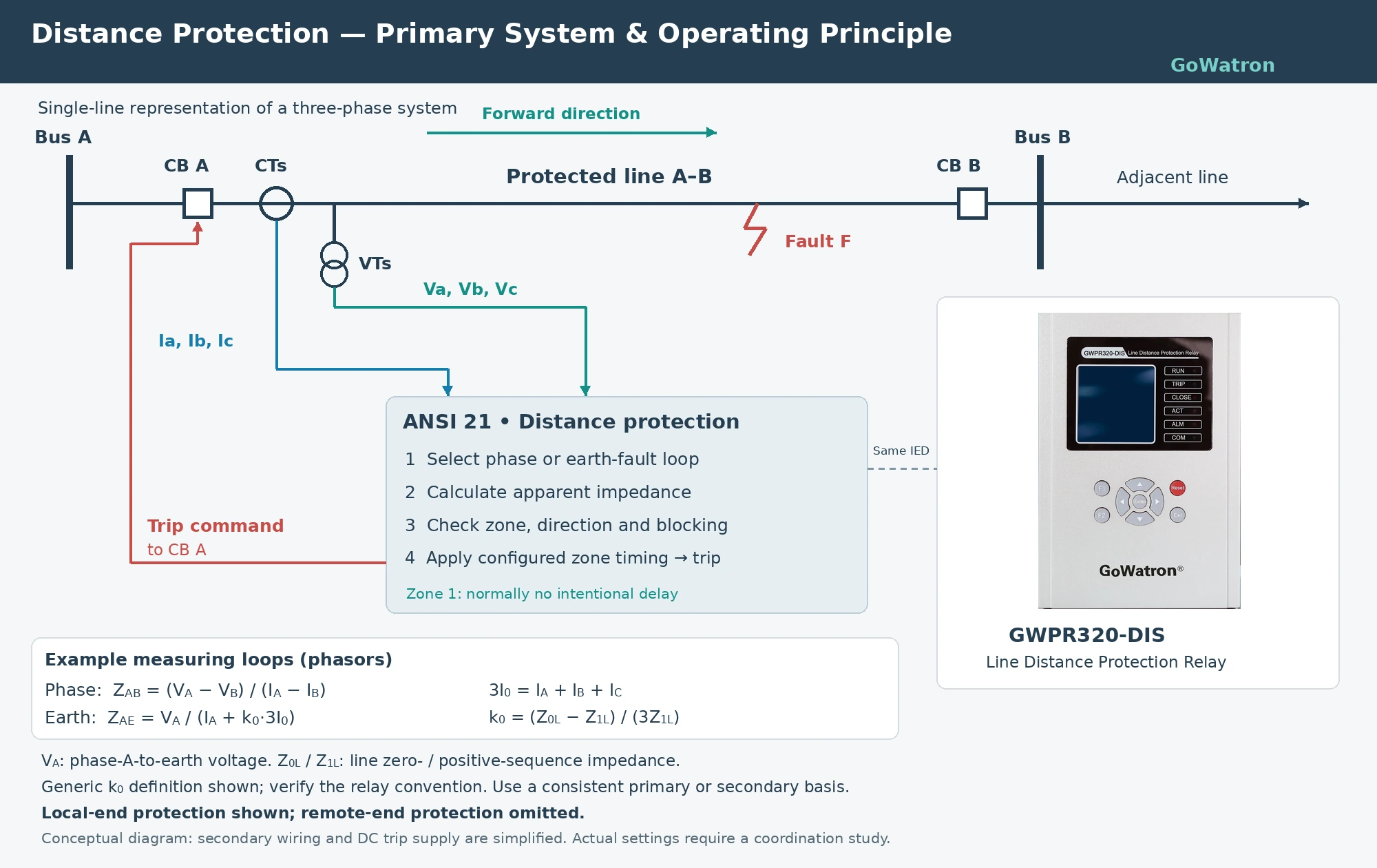
Different fault types require different measuring loops. For example, the measured impedance for the AB phase-to-phase loop is:
\[ \underline Z_{AB}= \frac{\underline U_A-\underline U_B} {\underline I_A-\underline I_B} \]
Under the applicable ideal line-model assumptions:
\[ \underline Z_{AB}\approx m\underline Z_L \]
where:
- \(\underline Z_L\) is the positive-sequence impedance of the entire protected line;
- \(m\) is the fraction of the total line length between the relay location and the fault.
Under these assumptions, a closer fault generally results in a smaller measured impedance magnitude. However, fault resistance, remote infeed, zero-sequence mutual coupling and measurement transients can affect the apparent impedance. Consequently, measured
impedance cannot always be converted directly into a physical distance in kilometres.
1.2 Determining Whether the Impedance Enters an Operating Region
The relay compares the position of the measured impedance on the resistance–reactance plane, or R–X plane, with the operating region defined by its configured characteristic.
Common characteristics include:
| Operating characteristic | Main features |
|
Plain impedance characteristic |
Its basic circular boundary is determined by impedance magnitude; directional supervision is normally required |
| Mho characteristic | Provides directional discrimination, with operating reach dependent on impedance magnitude and angle |
| Quadrilateral characteristic | Allows separate configuration of resistive and reactive boundaries to coordinate fault-resistance coverage with load avoidance |
Entry into the operating region does not necessarily result in an immediate trip. The applicable starting, directional, time-delay, blocking and permissive conditions must also be satisfied.
1.3 Achieving Coordination Through Zone Reach and Time Delays
Conventional three-zone distance protection uses different zone reach settings and operating time delays:
| Protection zone | Main purpose | Time-delay arrangement |
| Zone 1 | High-speed clearance of faults over most of the protected line | Normally no intentional time delay |
| Zone 2 | Time-delayed coverage of the entire protected line, with some reach into adjacent lines | Shorter intentional time delay |
| Zone 3 | Backup protection over a range established by the protection study | Longer intentional time delay |
The statement “more distant faults operate more slowly” is therefore only a simplified description of stepped distance protection. Faults at different locations within the same zone normally use the same set time delay.
Three-zone protection is a common arrangement. Numerical relays may provide additional zones and allow forward or reverse reach settings.
2. Main Functions of Distance Protection Relays (ANSI 21)
2.1 Selective Clearance of Line Faults
- Distance protection uses fault-loop apparent impedance to assess fault location. Coordination of zone reach settings and time delays helps limit disconnection to the required part of the network.
2.2 Reduced Dependence on Fault-Current Magnitude
- Compared with overcurrent protection that determines fault coverage primarily from current magnitude, distance protection reach is less dependent on changes in the short-circuit current level.
- However, distance protection is not completely independent of system operating conditions. Infeed, outfeed, multiterminal configurations, fault resistance and zero-sequence mutual coupling may cause overreach or underreach and must be assessed through fault studies.
2.3 Backup Protection
- Time-delayed distance zones can provide backup protection for the protected line and adjacent lines where coordination requirements are satisfied.
- The available backup coverage depends on network topology, infeed conditions, fault type, sensitivity and operating time. It cannot be determined from the zone number alone.
- 2.4 High-Speed Full-Line Clearance Using Communication-Assisted Schemes
- Conventional Zone 1 normally covers only part of the protected line. On its own, it cannot ensure high-speed tripping at both line terminals for every internal fault.
- Communication-assisted distance protection schemes exchange information between line terminals to enable high-speed clearance of faults throughout the protected line.
- For projects requiring distance protection, the GoWatron GWPR320-DIS Distance Protection Relay (ANSI 21) may be considered during equipment selection. The required zone configuration, operating characteristics, earth-fault (ground-fault) compensation and communication configuration should be checked against the project specification.
3. Information Required for Setting Calculations
Distance protection settings normally require the following information:
| Parameter category | Required information |
| Protected line | Length, positive-sequence impedance, zero-sequence impedance and impedance angle |
| Adjacent lines | Line impedances, protection reach settings and operating times |
| System operating conditions | Maximum and minimum fault levels and relevant line in-service and out-of-service conditions |
| Current and voltage circuits | CT and VT ratios and relevant measurement characteristics |
| Loading conditions | Minimum operating voltage, maximum permissible load current and load power factor |
| Special considerations | Fault resistance, multiterminal infeed and zero-sequence mutual coupling between parallel lines |
| Relay configuration | Operating characteristics, setting units, residual compensation definitions and associated logic |
\[ \underline z_1=r_1+jx_1 \]
\[ \underline Z_L=(r_1+jx_1)L \]
- \(r_1\) is the positive-sequence resistance per unit length, in Ω/km;
- \(x_1\) is the positive-sequence reactance per unit length, in Ω/km;
- \(L\) is the line length, in km.
\[ |\underline Z_L|=\sqrt{R_L^2+X_L^2} \]
\[ \theta_L=\arg(\underline Z_L) \]
4. Zone 1 Setting Calculations
4.1 Purpose and Setting Principle
- Zone 1 normally operates without intentional time delay and covers most of the protected line.
- Its reach is generally set short of the remote line terminal. A suitable margin is applied to prevent overreach during external faults due to line-parameter errors, measurement errors or transient effects.
- A commonly used illustrative reach setting is 80–85% of the protected line positive-sequence impedance. The actual setting must account for line length, measurement conditions, system characteristics and relay requirements.
4.2 Basic Formula
\[ \underline Z_{\mathrm{set,I}}=k_I\underline Z_L \]
- \(\underline Z_{\mathrm{set,I}}\) is the Zone 1 reach setting;
- \(k_I\) is the Zone 1 reach factor;
- -\(\underline Z_L\) is the positive-sequence impedance of the entire protected line.
4.3 Time Delay
\[ t_I=0\ \mathrm{s} \]
4.4 Calculation Example
\[ L=50\ \mathrm{km} \]
\[ \underline z_1=0.10+j0.40\ \Omega/\mathrm{km} \]
\[ \underline Z_L=(0.10+j0.40)\times50 =5+j20\ \Omega \]
\[ k_I=0.80 \]
\[ \underline Z_{\mathrm{set,I}} =0.80(5+j20) =4+j16\ \Omega \]
\[ \underline Z_{\mathrm{set,I}} \approx16.49\angle75.96^\circ\ \Omega \]
5. Zone 2 Setting Calculations
5.1 Purpose and Setting Principle
- Reliable coverage of faults at the remote terminal of the protected line;
- Reach coordination with adjacent-line protection;
- Time coordination with downstream protection;
- Infeed, outfeed and branch current effects;
- Sensitivity for the relevant fault types.
5.2 Simplified Coordination Formula
\[ \underline Z_{\mathrm{set,II}} = k_{\mathrm{coord}} \left( \underline Z_L+ K_b\underline Z_{\mathrm{set,I,next}} \right) \]
- \(k_{\mathrm{coord}}\) is a coordination margin factor;
- \(\underline Z_{\mathrm{set,I,next}}\) is the adjacent-line Zone 1 reach setting;
- \(K_b\) is the branch current factor defined for the network model used.
\[ K_b= \frac{\underline I_A+\underline I_B} {\underline I_A} \]
5.3 Time Delay
\[ t_{II}\geq t_{\mathrm{I,next}}+\Delta t \]
- \(t_{\mathrm{I,next}}\) is the relevant adjacent Zone 1 operating time delay;
- \(\Delta t\) is the coordination time margin.
5.4 Simplified Example
\[ \underline Z_L=5+j20\ \Omega \]
\[ \underline Z_{\mathrm{set,I,next}}=3+j12\ \Omega \]
\[ K_b=1,\qquad k_{\mathrm{coord}}=0.85 \]
\[ \underline Z_{\mathrm{set,II}} =0.85[(5+j20)+(3+j12)] \]
\[ \underline Z_{\mathrm{set,II}} =6.8+j27.2\ \Omega \]
6. Zone 3 Setting Calculations
6.1 Purpose and Setting Principle
Zone 3 normally provides time-delayed backup protection. Its reach setting and time delay must satisfy:
- Fault coverage within the specified backup area;
- Sensitivity under adverse operating conditions;
- Time coordination with downstream protection;
- Security under maximum loading and low-voltage operating conditions;
- Relevant requirements for non-fault conditions, including power swings.
The Zone 3 reach setting cannot be determined solely from the minimum load impedance and a set of factors. Load avoidance is one constraint; it does not replace backup-reach and sensitivity calculations.
6.2 Backup-Reach Assessment
For a simple network model, neglecting fault resistance and other additional effects, the apparent impedance for a remote fault may be represented as:
\[ \underline Z_{\mathrm{app}} = \underline Z_L+ K_b\underline Z_{\mathrm{adj}} \]
where:
- \(\underline Z_{\mathrm{app}}\) is the apparent impedance seen by the local relay;
- \(\underline Z_{\mathrm{adj}}\) is the adjacent-line impedance from the remote bus to the intended backup fault location;
- \(K_b\) is the branch current factor for that model.
The setting study should calculate apparent impedance for the relevant operating conditions and fault types, then determine the Zone 3 reach setting using the relay operating characteristic and coordination requirements.
6.3 Minimum Load Impedance Check
For a balanced three-phase load, using phase-to-neutral voltage:
\[ |Z_{\mathrm{load,min}}| = \frac{U_{\mathrm{ph,min}}} {I_{\mathrm{load,max}}} \]
Using phase-to-phase voltage:
\[ |Z_{\mathrm{load,min}}| = \frac{U_{\mathrm{LL,min}}} {\sqrt3 I_{\mathrm{load,max}}} \]
where:
- \(U_{\mathrm{ph,min}}\) is the minimum operating phase-to-neutral voltage;
- \(U_{\mathrm{LL,min}}\) is the minimum operating phase-to-phase voltage;
- \(I_{\mathrm{load,max}}\) is the maximum permissible load current.
If minimum voltage and maximum current do not occur simultaneously, this expression may be used to establish a conservative check. The assessment should also consider credible combinations of operating voltage and loading.
The load power factor must then be used to determine the load impedance angle. The resulting load region should be checked against the relay operating region, with an appropriate margin.
For quadrilateral characteristics, the resistive and reactive boundaries and the configuration of any load-encroachment logic must also be checked.
6.4 Time Delay
For stepped time coordination:
\[ t_{III}\geq t_{\mathrm{downstream}}+\Delta t \]
where \(t_{\mathrm{downstream}}\) is the operating time of the downstream protection with which coordination is required.
The selected time delay must correspond to the intended backup coverage. A single fixed value is not suitable for every application.
7. Residual Compensation for Earth-Fault Distance Protection
- Earth-fault distance protection also uses the distance-measuring principle. Some manufacturers use designations such as 21G or 21N to identify earth-fault distance elements. The specific suffix should follow the manufacturer’s documentation.
- An earth-fault loop contains zero-sequence components. Residual compensation is normally applied so that, under the applicable conditions, the measured impedance corresponds to the positive-sequence line impedance between the relay location and the fault.
8. Converting Between Primary and Secondary Impedance
8.1 Basic Formula
Define the CT and VT ratios as the rated primary quantity divided by the corresponding rated secondary quantity:
\[ n_{\mathrm{CT}} = \frac{I_{\mathrm{pri,rated}}} {I_{\mathrm{sec,rated}}} \]
\[ n_{\mathrm{VT}} = \frac{U_{\mathrm{pri,rated}}} {U_{\mathrm{sec,rated}}} \]
The secondary impedance is:
\[ \underline Z_{\mathrm{sec}} = \underline Z_{\mathrm{pri}} \frac{n_{\mathrm{CT}}}{n_{\mathrm{VT}}} \]
The reverse conversion is:
\[ \underline Z_{\mathrm{pri}} = \underline Z_{\mathrm{sec}} \frac{n_{\mathrm{VT}}}{n_{\mathrm{CT}}} \]
The numerator and denominator of the VT ratio must use consistent phase-to-phase or phase-to-neutral voltage definitions.
8.2 Calculation Example
Assume:
\[ n_{\mathrm{CT}}=\frac{600}{1}=600 \]
\[ n_{\mathrm{VT}}=\frac{110000}{100}=1100 \]
The primary Zone 1 reach setting is:
\[ \underline Z_{\mathrm{set,I,pri}} =4+j16\ \Omega \]
The corresponding secondary setting is:
\[ \underline Z_{\mathrm{set,I,sec}} =(4+j16)\frac{600}{1100} \]
\[ \underline Z_{\mathrm{set,I,sec}} \approx2.18+j8.73\ \Omega \]
Some numerical relays accept settings directly in primary ohms after the CT and VT ratios have been entered. Confirm the required setting units before entering values to avoid double conversion.
9. Key Setting Considerations for Distance Protection Relays (ANSI 21)
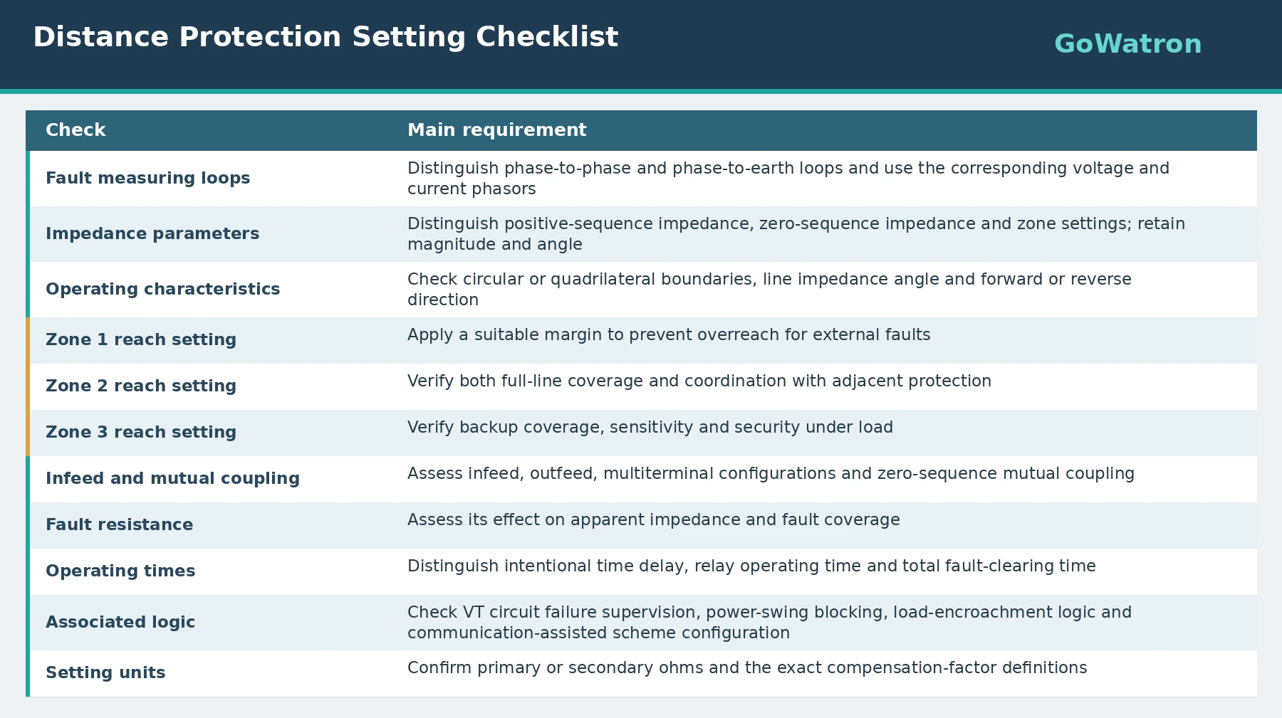
For projects using the GoWatron GWPR320-DIS Distance Protection Relay, zone reach settings, operating time delays and residual compensation parameters should be based on the line protection study and entered in accordance with the applicable relay manual revision. The equations and examples in this article explain the calculation principles; they are not recommended settings for this model.


