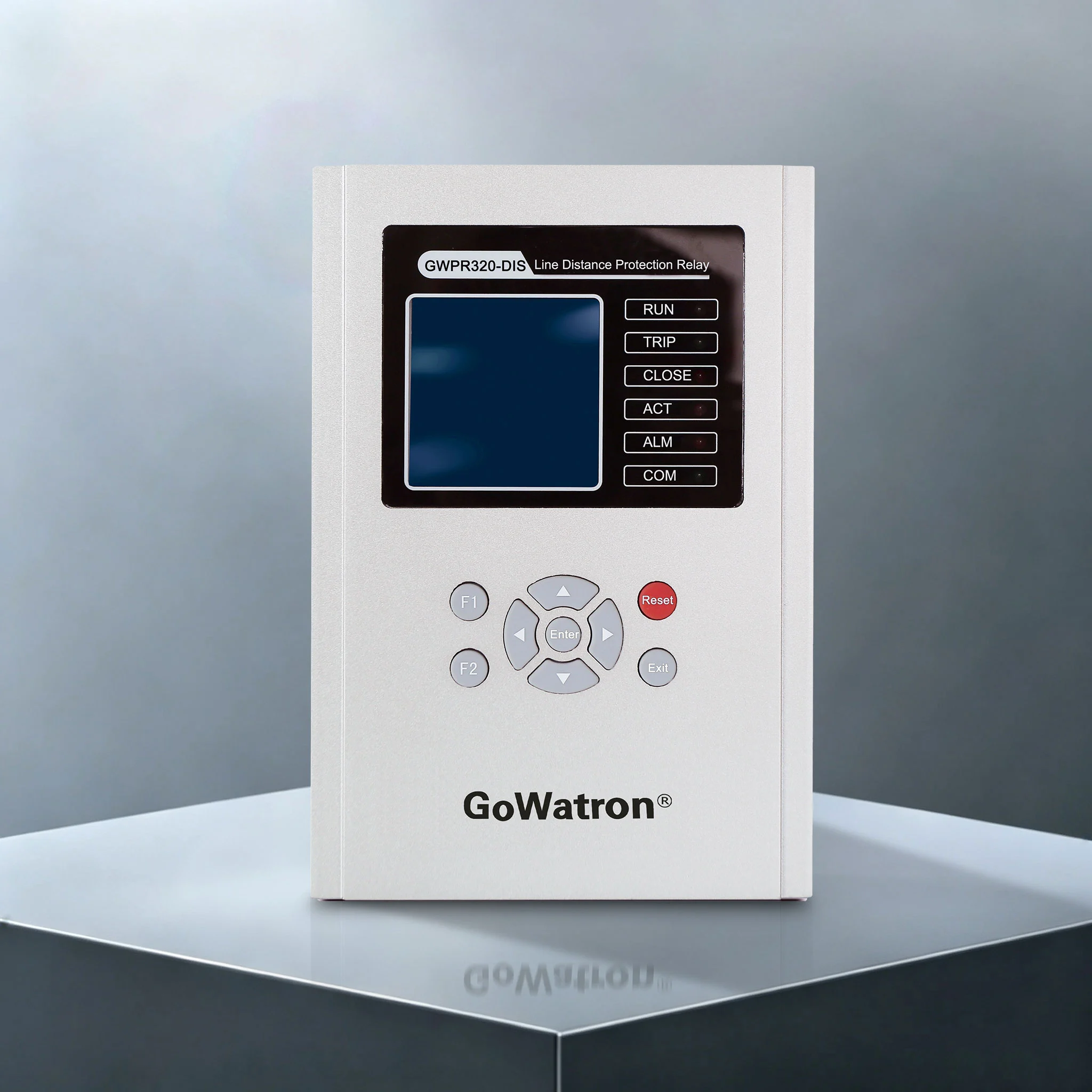
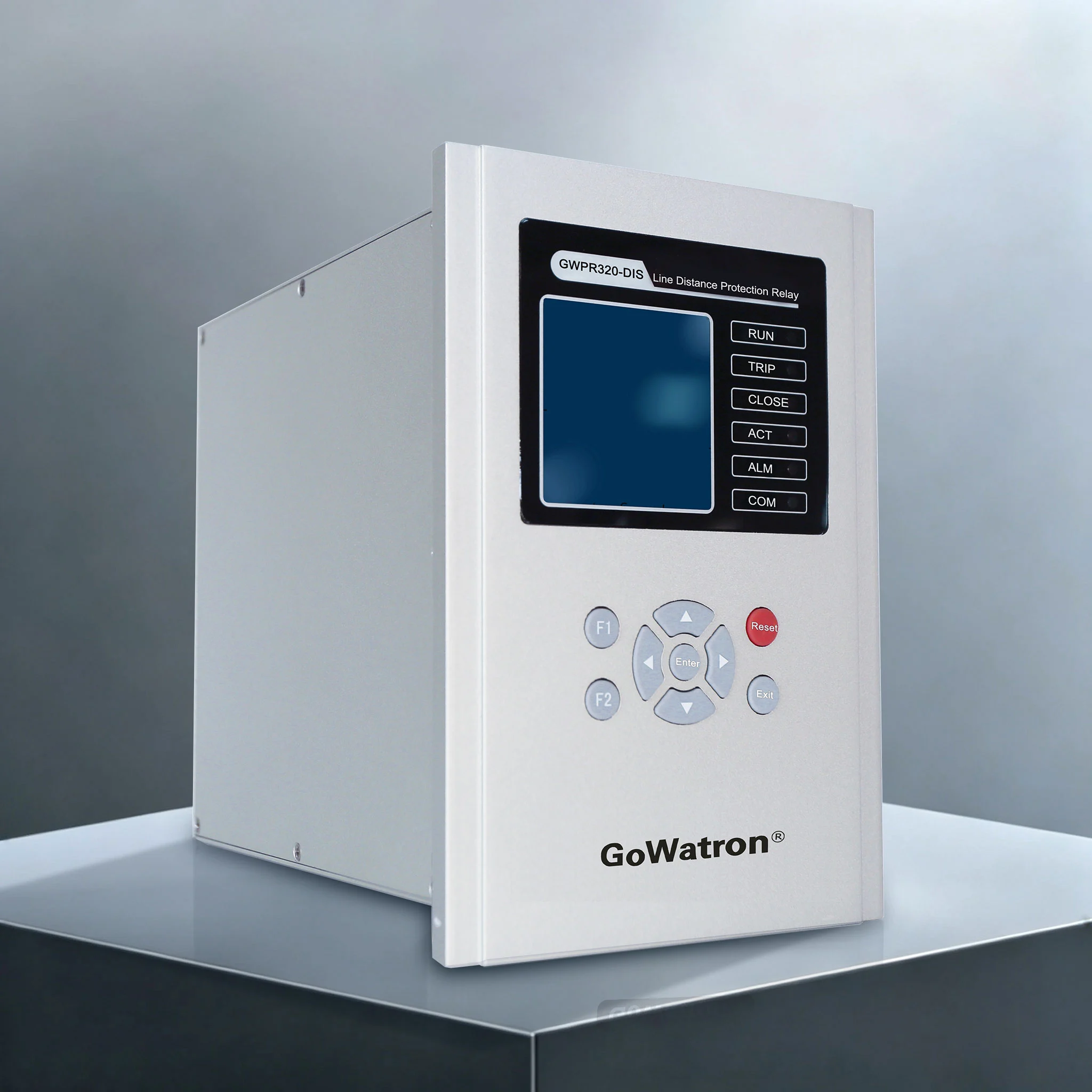

GWPR320-DIS Line Distance Protection Relay
Product Desc
GWPR320-DIS numerical Line Distance Protection Relay is independently developed and manufactured by GoWatron. It is specially designed for 35kV and below distribution lines with neutral ungrounded or resistance-earthed power systems. The device supports both on-site cabinet mounting and control room panel mounting, integrating comprehensive fault protection, fault location, three-phase auto-reclosing and four-remote functions (telemetry, telesignalling, telecontrol, teleregulation) into one single unit.
- It is equipped with dual Ethernet ports and RS485 dual communication interfaces, compatible with most substation integrated automation systems.
- Standard communication protocols: IEC 60870-5-103, IEC 60870-5-104, Modbus RTU/TCP. These protocols fully support uploading telemetry data, telesignalling status, fault records and protection settings.
- Optional communication protocol: IEC 61850 (supports MMS and GOOSE), which satisfies the networking requirements of intelligent digital substations.




Accuracy
≤ 0.2%

Quick Response
≤ 100ms

Reliable Protection
Comprehensive Protection

Quality Assurance
ISO 9001 Certified

Technical Support
24/7 Expert Support

Fast Delivery
Global Shipping

Warranty
2-Year Warranty
Protection Functions
Distance Protection (ANSI 21 Series)
- (ANSI 21) Phase Distance Protection: Three-zone quadrilateral offset impedance (Zone Ⅰ/Ⅱ/Ⅲ), fitted with a positive-sequence directional element to eliminate the zone outlet dead zone. It adopts built-in 150ms temporary enable logic coordinated with out-of-step blocking to avoid maloperation.
- (ANSI 21N) Ground Distance Protection: Three-zone ground offset impedance protection with zero-sequence reactance elements, which suppress protection overreach induced by transition resistance during single-phase earth faults.
- (ANSI 21FL) Fault Locator: The location error for metallic short-circuit faults is limited to ±2%, enabling fast and precise fault point identification along transmission lines.
- (ANSI 68) Out-of-Step Blocking Protection: Adopts dual judging criteria: impedance change rate dZ/dt and asymmetric fault enable logic. It blocks Zone Ⅰ and Ⅱ distance protection during system oscillation, while reliably tripping for internal faults.
- Auxiliary high-speed acceleration logic: Asymmetrical successive acceleration and double-circuit successive acceleration, both capable of accelerating Zone Ⅱ distance tripping.
Phase Overcurrent Protection (ANSI 50/51/67 Series)
- (ANSI 50) Instantaneous Overcurrent Protection: Zone Ⅰ instantaneous phase fault protection, clears near-end phase faults within ms.
- (ANSI 51) Definite-Time Phase Overcurrent Protection: Graded time-delay protection for Zone Ⅱ and Zone Ⅲ. Current threshold and delay time can be set independently to realize selective coordination between upstream and downstream protections.
- (ANSI 51I) Inverse-Time Phase Overcurrent Protection: Compatible with standard, very inverse and extremely inverse-time characteristic curves for time grading coordination in multi-level distribution networks.
- (ANSI 67) Directional Phase Overcurrent Protection: Adopts 90° phase-shift connection directional logic. It blocks protection against reverse faults to prevent mal-tripping caused by external faults.
- (ANSI 51V) Voltage-Restrained Overcurrent Protection: Blocks overcurrent protection under motor back-feed and no-load operating conditions to eliminate maloperation risks.
Zero-Sequence Earth Fault Protection (ANSI 50N/51N/67N Series)
- (ANSI 50N) Instantaneous Zero-Sequence Overcurrent Protection: Zone Ⅰ instantaneous earth fault protection for rapid isolation of near-end single-phase earth faults.
- (ANSI 51N) Definite-Time Zero-Sequence Overcurrent Protection: Time-delayed earth fault protection for Zone Ⅱ and Zone Ⅲ, applicable to high-resistance earth faults on long-distance overhead lines.
- (ANSI 51NI) Inverse-Time Zero-Sequence Overcurrent Protection: Dedicated inverse-time characteristics for earth faults, achieving sequential coordination of earth fault protection on segmented lines.
- (ANSI 67N) Directional Zero-Sequence Overcurrent Protection: Direction discrimination based on self-residual voltage (3U0), reliably blocking protection responses to external earth faults.
Auto-Reclosing & Fault Acceleration (ANSI 79/25)
- (ANSI 79) Three-Phase Single-Shot Auto-Reclosing: Dual trigger modes: protection tripping trigger / circuit breaker position mismatch trigger. It features a 15s charging cycle. The reclosing circuit will discharge and lock out under the following conditions: spring energy storage incomplete, control circuit disconnection, external blocking signal input.
- (ANSI 25) Synchronism Check / Dead Bus Check Closing: Four configurable closing modes: Non-synchronism, Synchronism Check, Dead Bus Check, Synchronism + Dead Bus Check.
- Auxiliary acceleration functions: Manual close fault acceleration; switchable pre-acceleration / post-acceleration mode. Independent current thresholds and delay settings are available for phase and zero-sequence acceleration zones.
Voltage & Frequency Stabilization Control and Circuit Supervision (ANSI 27/60/81L)
- (ANSI 27) Under-Voltage Load Shedding Protection: Triggers time-delayed load shedding when three-phase voltage falls below the set threshold. Equipped with dual blocking logics based on voltage change rate and negative-sequence voltage to prevent false tripping.
- (ANSI 60) VT Fuse Failure Supervision: Automatically detects three-phase voltage loss, single/two-phase VT disconnection and generates active alarm signals. Users may selectively disable all directional and voltage-restrained protection functions upon detection.
- (ANSI 81L) Under-Frequency Load Shedding Protection: Automatically sheds loads when system frequency drops below threshold. Triple blocking criteria (rate of change of frequency (df/dt), undervoltage, line active load) distinguish genuine power shortage from transient fault conditions.
Load Supervision & Device Self-Check (ANSI 49)
- (ANSI 49) Overload Protection: Monitors three-phase overload current exceeding set value, supporting two output modes: Alarm Only or Time-Delayed Trip.
- Hardware self-check function: Uploads real-time alarm information for RAM/ROM/AD sampling errors, invalid protection settings, output loop failures and dual communication port malfunctions.
Core Technical Parameters
- Power Supply: DC 110V/220V, AC 220V (configurable on order)
- AC Analog Input: CT secondary rated current 1A / 5A; VT line voltage 100V; Rated frequency 50Hz
- Measurement Accuracy: Class 0.2 for voltage and current; Class 0.5 for active/reactive power and electrical energy
- Operating Speed: Operating time ≤40ms at 1.2 times the instantaneous zone setting
- Fault Location Precision: Metallic fault positioning error ≤±2%
- Timing Accuracy: Max error ≤25ms for delays ranging 0~1s; Max error ≤±2.5% for delays over 1s
Application Scenarios
- Applicable Voltage Level: Medium and low-voltage distribution lines of 35kV and below
- Applicable Power Grid: Neutral ungrounded distribution system, resistance-earthed distribution system
- Applicable Line Types: Single-circuit distribution feeders, double-circuit parallel feeders
- Installation Methods: On-site cabinet mounting, centralized panel mounting in substation control room
- Application Sites: Urban and rural distribution substations, industrial and mining power distribution rooms, park integrated automation power distribution cabinets, digital intelligent substations (requires optional IEC 61850 module)


