Overvoltage Protection Relay (ANSI 59): Working Principle, Functions and Setting Calculations
- An overvoltage protection relay is a digital protection device designed to detect abnormal voltage rises in electrical power systems and initiate alarms, circuit-breaker tripping or other control actions according to predefined voltage thresholds, operating delays and protection logic.
- The ANSI device function number for overvoltage protection is 59. This protection function is primarily used to detect sustained power-frequency overvoltages and is widely applied in 33 kV and 11 kV distribution systems, substations, generators, transformers, capacitor banks and renewable energy grid connections.
- When the measured voltage exceeds the configured pickup threshold and remains above the threshold for the specified time delay, the relay initiates the assigned protection action, provided that all applicable operating and blocking conditions are satisfied.
- Overvoltage protection settings involve more than calculating a voltage threshold. Proper coordination requires consideration of voltage transformer (VT/PT) ratios, reset characteristics, operating times, equipment voltage withstand capabilities and other protection functions.
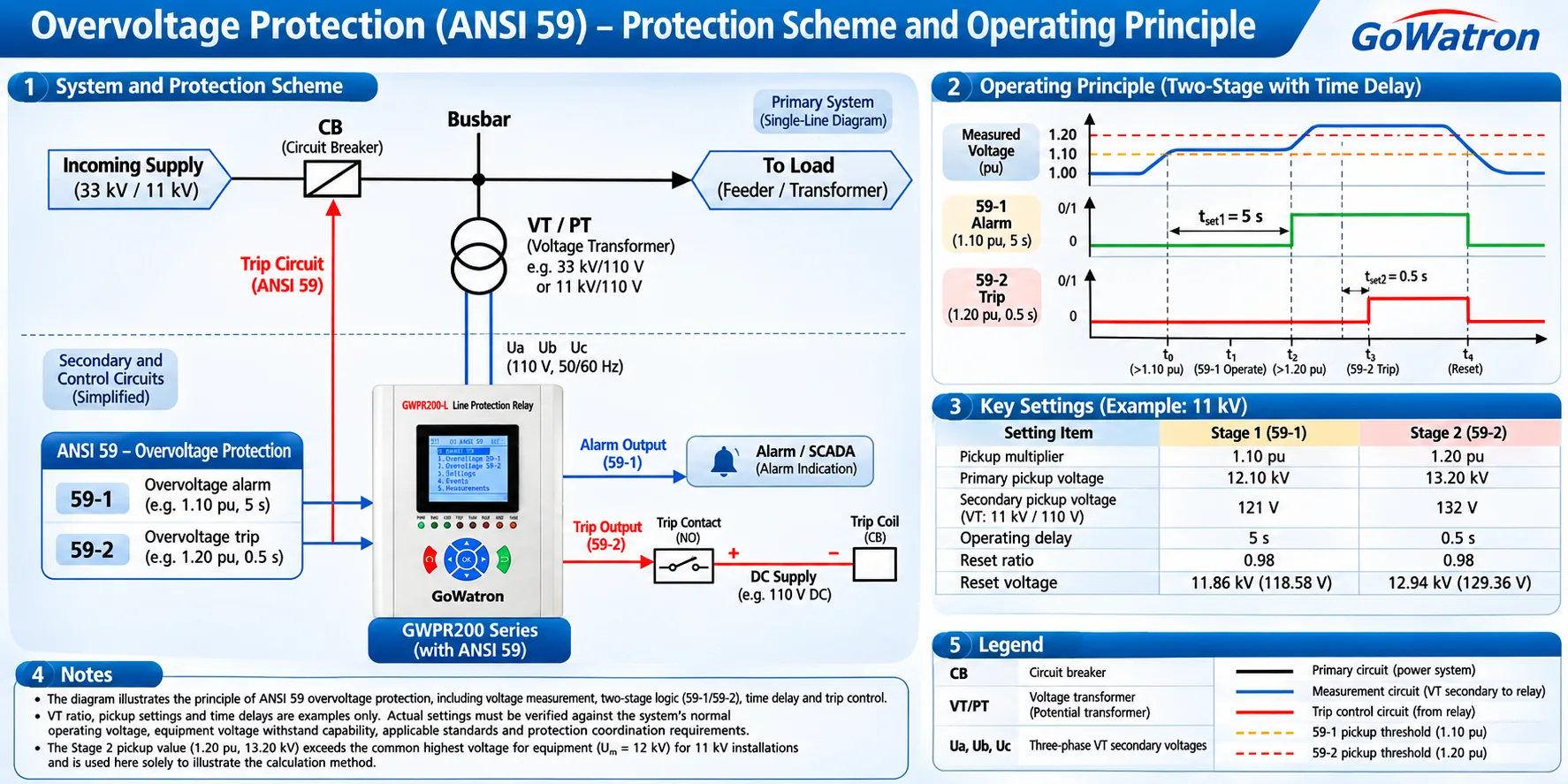
1. Working Principle of an Overvoltage Protection Relay
1.1 Basic Working Principle
- A digital overvoltage protection relay typically measures system voltage through voltage transformers (VTs/PTs), which transform the primary system voltage into a suitable secondary voltage for the relay.
- The relay processes the analogue voltage signals through signal conditioning, analogue-to-digital (A/D) conversion and digital calculations to obtain the voltage values used by its protection algorithms.
- These measured values are continuously compared with predefined pickup settings.
The basic operating sequence is:
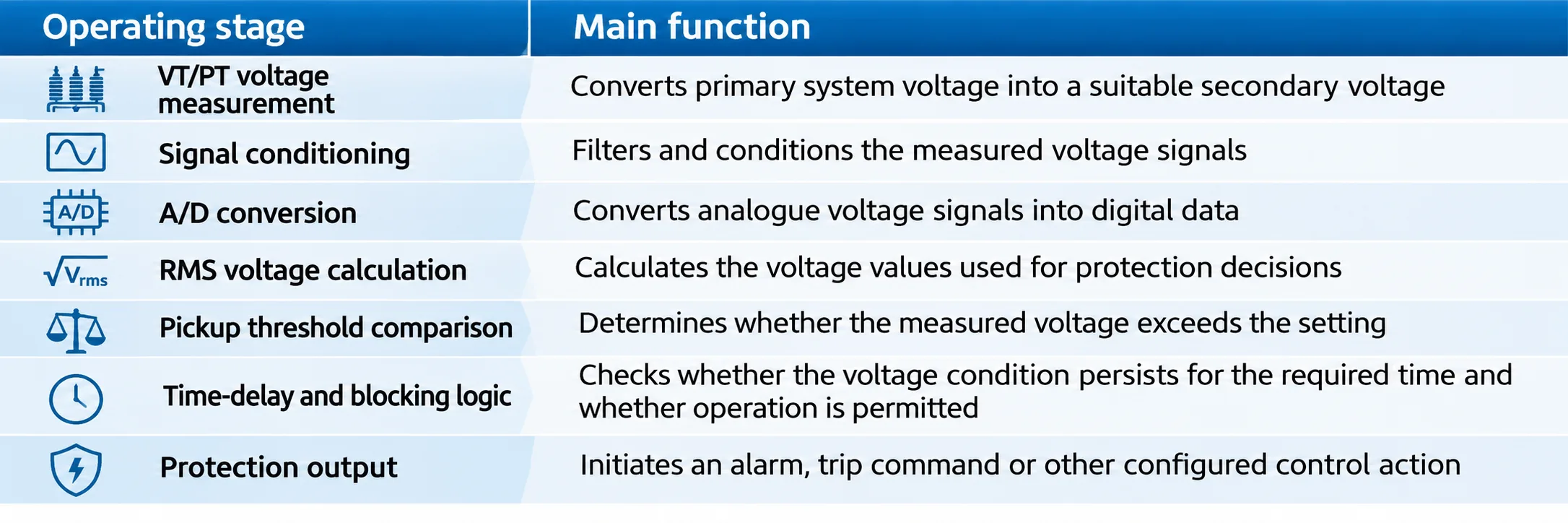
VT/PT Voltage Measurement → Signal Conditioning → A/D Conversion → RMS Voltage Calculation → Pickup Threshold Comparison → Time-Delay and Blocking Logic → Protection Output
The main functions of each stage are described below.
1.2 Overvoltage Protection Pickup Conditions
The basic pickup condition for overvoltage protection is:
\[ \boxed{U_{\mathrm{meas}}>U_{\mathrm{set}}} \]
Where:
- \(U_{\mathrm{meas}}\): Measured voltage.
- \(U_{\mathrm{set}}\): Overvoltage pickup setting.
When the measured voltage exceeds the pickup threshold, the voltage pickup condition is satisfied.
- For definite-time overvoltage protection, the relay initiates the configured output when the overvoltage condition persists for the specified time delay, provided that no applicable blocking condition prevents operation.
- If the voltage subsequently falls below the reset threshold, the protection element resets according to the relay’s configured reset logic.
- Pickup does not necessarily mean immediate tripping. Actual operation depends on the time-delay setting, blocking conditions and output configuration.
1.3 Overvoltage Protection Logic
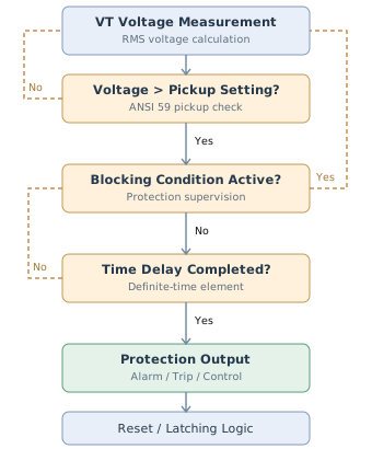
Figure 1. Simplified ANSI 59 overvoltage protection logic. The actual timer, blocking and reset behaviour depends on the relay configuration. The diagram illustrates the functional sequence rather than the exact internal implementation
- Typical overvoltage protection logic includes voltage measurement, pickup detection, blocking supervision, time-delay processing, output operation and reset.
- If the measured voltage does not satisfy the pickup condition, the protection element remains inactive.
- If an applicable blocking condition is active, the relay prevents the associated protection output.
- If the voltage falls below the reset threshold before the operating delay expires, the relay processes the condition according to its configured reset characteristics.
1.4 Overvoltage Protection Operating Sequence
- The operating sequence generally includes voltage threshold crossing, pickup detection, time-delay processing, output operation and reset.
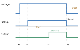
Figure 2. Illustrative overvoltage protection operating sequence. t₀ is the threshold-crossing instant, t₁ is pickup detection, t₂ is output operation and t₃ represents reset following voltage recovery. The diagram assumes a non-latching output and a voltage recovery sufficient to satisfy the reset condition.
- The actual operating time includes voltage detection and output processing, while the output may remain latched depending on the relay configuration.
- Voltage falling below the pickup threshold does not necessarily cause immediate reset; the configured reset threshold must also be satisfied.
2. Main Types of Overvoltage Protection
2.1 Phase Overvoltage Protection (ANSI 59)
Phase overvoltage protection monitors phase-to-neutral or phase-to-phase voltage to determine whether the measured voltage exceeds a specified threshold.
Depending on the relay’s capabilities and configuration, the protection logic may operate when:
- Any phase-to-neutral voltage exceeds the pickup setting.
- Any phase-to-phase voltage exceeds the pickup setting.
- All three monitored voltages exceed the pickup setting.
- The positive-sequence voltage exceeds the pickup setting, where supported.
The measurement method and operating logic vary between relay manufacturers.
The relay’s technical documentation should therefore be consulted when selecting the voltage reference and pickup criteria.
2.2 Residual Overvoltage Protection (ANSI 59N)
Residual overvoltage protection is used to detect residual voltage or neutral voltage displacement, particularly in earth-fault detection applications.
For three measured phase-to-earth voltage phasors:
\[ \boxed{3\vec U_0=\vec U_a+\vec U_b+\vec U_c} \]
The magnitude of the residual voltage is:
\[ \boxed{ U_{\mathrm{res}}= \left|\vec U_a+\vec U_b+\vec U_c\right| } \]
Where:
- \(U_0\): Zero-sequence voltage.
- \(U_{\mathrm{res}}\): Residual voltage magnitude.
- \(\vec U_a,\vec U_b,\vec U_c\): Phase-to-earth voltage phasors.
Under balanced operating conditions, the vector sum of the three phase voltages is approximately zero.
During an earth fault or significant neutral displacement, the residual voltage may increase and initiate the protection element.
Some relays use \(U_0\) as the setting reference, while others use \(3U_0\).
These quantities differ by a factor of three and must not be interchanged without checking the relay’s setting definitions.
2.3 Negative-Sequence Voltage Protection (ANSI 47)
Negative-sequence voltage protection is used to detect voltage unbalance in three-phase systems.
The negative-sequence voltage can be calculated as:
\[ \boxed{ \vec U_2= \frac{1}{3} \left( \vec U_a+a^2\vec U_b+a\vec U_c \right) } \]
Where:
\[ a=e^{j120^\circ} \]
This expression assumes the conventional A-B-C positive phase sequence.
Negative-sequence voltage protection is commonly associated with voltage unbalance and phase-sequence supervision.
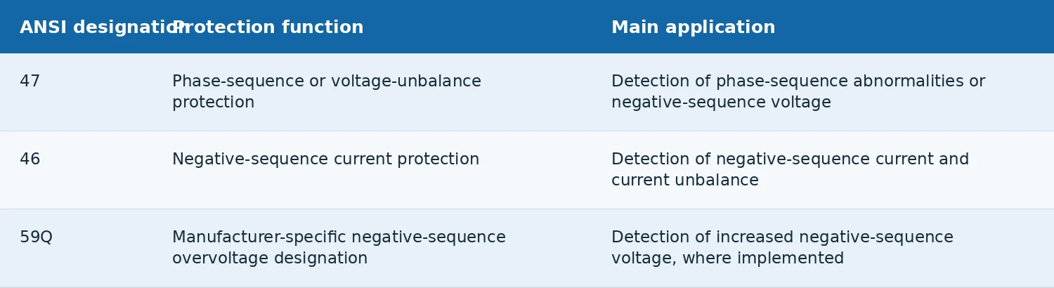
ANSI 59Q is not universally adopted by relay manufacturers.
For cross-manufacturer technical documentation, ANSI 47 is generally the more recognisable designation for phase-sequence or voltage-unbalance protection. However, the exact protection element and measurement criteria must be confirmed in the relevant manufacturer’s documentation.
2.4 Multi-Stage Overvoltage Protection
- Some digital protection relays provide two or more independent overvoltage stages.
- Each stage may have separately configurable voltage pickup thresholds, operating time delays, alarm or trip outputs, reset characteristics and blocking conditions.
- For example, one stage may provide sustained overvoltage alarming, while another stage may initiate equipment disconnection at a higher voltage threshold.
- The number of available stages and their functions depend on the relay model and configuration.
3. Main Functions and Applications of Overvoltage Protection Relays
3.1 Protection Against Sustained Overvoltage
- Sustained overvoltage can increase electrical insulation stress and adversely affect equipment service life.
- An overvoltage protection relay monitors the system voltage and initiates the configured protective action when the measured voltage exceeds the specified threshold for the required duration.
- This function is applicable to transformers, generators, motors and other electrical equipment requiring voltage supervision.
3.2 Generator Overvoltage Protection
- Generator terminal voltage may rise following sudden load rejection, excitation control abnormalities or automatic voltage regulator (AVR) malfunctions.
- Overvoltage protection can be coordinated with the excitation control system and other generator protection functions to reduce the risk associated with sustained overvoltage.
3.3 Substation Busbar Overvoltage Protection
- In 33 kV and 11 kV substations, busbar voltage may rise due to changes in network operating conditions, reactive power compensation or load demand.
- Overvoltage protection can continuously monitor busbar voltage and initiate alarms or control actions according to the approved operating scheme.
3.4 Capacitor Bank Overvoltage Protection
- Switching a shunt capacitor bank into service may cause an increase in busbar voltage.
- Overvoltage protection can be coordinated with reactive power compensation controls to detect sustained voltage abnormalities and, where appropriate, disconnect the relevant capacitor bank.
3.5 Renewable Energy Grid-Connection Protection
- In photovoltaic (PV) and wind power systems, high local generation output, network impedance and reactive power control can contribute to voltage rises at the point of connection.
- Overvoltage protection may be part of the grid-interface protection scheme.
- Its pickup thresholds and operating delays must comply with applicable grid codes, network operator requirements and equipment operating limits.
3.6 Scope and Limitations of ANSI 59 Protection
- ANSI 59 protection is primarily intended to detect sustained power-frequency overvoltage and other voltage abnormalities within the relay’s measurement and response capabilities.
- Lightning impulses and fast switching overvoltages generally have very short durations and cannot be adequately limited by conventional ANSI 59 protection alone.
- Such transient overvoltages are normally addressed through surge arresters, insulation coordination and appropriate system design.
4. Overvoltage Protection Setting Calculations
Overvoltage protection settings normally include voltage pickup thresholds, operating time delays, reset characteristics and relevant blocking logic.
4.1 Voltage Pickup Setting Formula
An initial overvoltage pickup setting can be calculated using:
\[ \boxed{ U_{\mathrm{set}}= K_{\mathrm{set}}\times U_{\mathrm n} } \]
Where:
- \(U_{\mathrm{set}}\): Overvoltage pickup setting.
- \(K_{\mathrm{set}}\): Voltage setting multiplier.
- \(U_{\mathrm n}\): Rated voltage reference consistent with the relay’s measurement configuration.
Setting multipliers such as 1.05–1.20 pu may be used for illustrative calculations.
However, this range must not be interpreted as a universally recommended setting range for all equipment.
Actual settings should consider the maximum normal operating voltage, VT and relay measurement errors, equipment voltage withstand capabilities and protection coordination requirements.
4.2 Setting Calculation for a 33 kV System
Assume the following:
- Rated system voltage: 33 kV.
- VT ratio: 33 kV/110 V.
- Voltage setting multiplier: 1.10.
- Relay measurement: Phase-to-phase voltage.
The primary-side pickup voltage is:
\[ U_{\mathrm{set,pri}}=33\times1.10 \]
\[ \boxed{ U_{\mathrm{set,pri}}=36.30\ \mathrm{kV} } \]
The VT ratio is:
\[ K_{\mathrm{VT}}= \frac{33000}{110}=300 \]
The secondary-side pickup voltage is:
\[ U_{\mathrm{set,sec}}= \frac{36300}{300} \]
\[ \boxed{ U_{\mathrm{set,sec}}=121\ \mathrm V } \]
- Under these assumptions, the relay pickup threshold is 121 V on the secondary side, equivalent to 1.10 pu.
- Common 33 kV equipment is associated with a highest voltage for equipment of 36 kV.
- The calculated 36.30 kV value exceeds this voltage class and must not be adopted as an actual trip setting without engineering verification.
4.3 Setting Calculation for an 11 kV System
Assume:
- Rated system voltage: 11 kV.
- VT ratio: 11 kV/110 V.
- Voltage setting multiplier: 1.10.
- Relay measurement: Phase-to-phase voltage.
Primary-side pickup voltage:
\[ U_{\mathrm{set,pri}}=11\times1.10 \]
\[ \boxed{ U_{\mathrm{set,pri}}=12.10\ \mathrm{kV} } \]
VT ratio:
\[ K_{\mathrm{VT}}= \frac{11000}{110}=100 \]
Secondary-side pickup voltage:
\[ U_{\mathrm{set,sec}}= \frac{12100}{100} \]
\[ \boxed{ U_{\mathrm{set,sec}}=121\ \mathrm V } \]
For common 11 kV equipment with a highest voltage for equipment of 12 kV, the calculated pickup voltage requires verification against equipment voltage withstand characteristics and operating requirements.
4.4 Setting Calculations for Different Voltage Levels
The following calculations use the rated phase-to-phase system voltage as the 1.00 pu reference.
For a 0.4 kV system, 400 V is used as the rated phase-to-phase voltage. Therefore, 1.05–1.20 pu corresponds to 420–480 V.
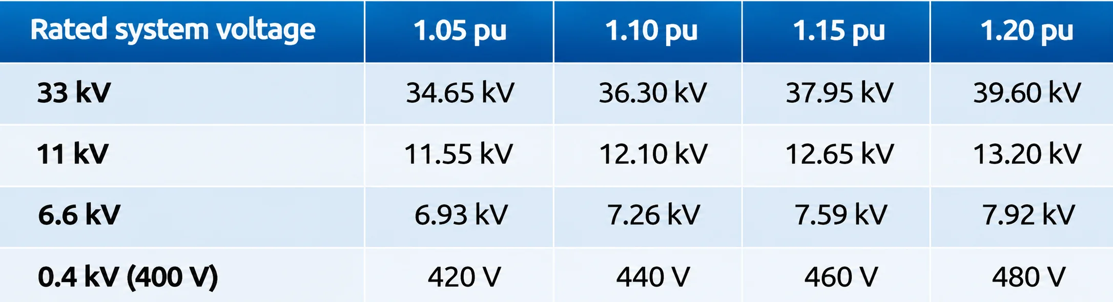
These values are mathematical examples based on rated voltage. They do not represent permissible continuous operating voltages or recommended protection settings.
4.5 Setting Calculation Using a Reliability Margin
In practical applications, the pickup threshold should account for the maximum normal operating voltage, measurement errors and an appropriate reliability margin.
One preliminary approach is:
\[ \boxed{ U_{\mathrm{set}}\ge K_{\mathrm{rel}}\times U_{\mathrm{max,normal}} } \]
Where:
\(K_{\mathrm{rel}}\): Reliability factor.
\(U_{\mathrm{max,normal}}\): Maximum continuous voltage expected under normal operating conditions.
For example, assume an 11 kV system has a maximum normal operating voltage of 11.55 kV.
Using an illustrative reliability factor of 1.05:
\[ U_{\mathrm{set}}\ge1.05\times11.55 \]
\[ \boxed{ U_{\mathrm{set}}\ge12.1275\ \mathrm{kV} } \]
In per-unit form:
\[ U_{\mathrm{set,pu}}\ge \frac{12.1275}{11} \]
\[ \boxed{ U_{\mathrm{set,pu}}\ge1.1025 } \]
Under these assumptions, a pickup threshold of approximately 1.103 pu or higher would satisfy the selected reliability margin.
The reliability factor is used solely to demonstrate the calculation method and is not a universal engineering value.
If the calculated pickup threshold exceeds the equipment’s permissible voltage withstand capability, the voltage regulation and protection scheme must be reassessed rather than simply increasing the pickup setting.
4.6 Primary-to-Secondary Voltage Conversion
Protection relays normally measure the VT secondary voltage.
Therefore, primary voltage settings must be converted using the VT transformation ratio.
\[ \boxed{ K_{\mathrm{VT}}= \frac{U_{\mathrm{VT,pri}}} {U_{\mathrm{VT,sec}}} } \]
The secondary pickup voltage is:
\[ \boxed{ U_{\mathrm{set,sec}}= \frac{U_{\mathrm{set,pri}}} {K_{\mathrm{VT}}} } \]
Where:
- \(U_{\mathrm{VT,pri}}\): Rated VT primary voltage.
- \(U_{\mathrm{VT,sec}}\): Rated VT secondary voltage.
- \(K_{\mathrm{VT}}\): VT transformation ratio.
The primary and secondary quantities must use consistent voltage definitions.
Phase-to-phase voltages must be compared with phase-to-phase voltages, and phase-to-neutral voltages with phase-to-neutral voltages.
For relays using a nominal phase-to-neutral input of \(110/\sqrt3\) V, the setting must be converted according to the actual VT connection and the relay’s voltage reference.
5. Overvoltage Protection Operating Time and Coordination
5.1 Definite-Time Overvoltage Protection
Definite-time overvoltage protection operates after a preset delay when the measured voltage exceeds the pickup threshold and no applicable blocking condition prevents operation.
For an ideal definite-time protection element, the logic timing interval is:
\[ \boxed{ t_{\mathrm{logic}}=t_{\mathrm{set}} } \]
Where:
\(t_{\mathrm{logic}}\): Ideal protection logic timing interval.
\(t_{\mathrm{set}}\): Configured operating delay.
The logic timing interval is not necessarily equal to the relay’s actual total operating time.
For explanatory purposes, the total operating time may be represented approximately as:
\[ \boxed{ t_{\mathrm{total}}\approx t_{\mathrm{detect}}+ t_{\mathrm{set}}+ t_{\mathrm{output}} } \]
Where:
- \(t_{\mathrm{total}}\): Time from the occurrence of the overvoltage condition to the operation of the relay output contact.
- \(t_{\mathrm{detect}}\): Time required for voltage sampling, filtering, calculation and pickup detection.
- \(t_{\mathrm{output}}\): Time required for output processing and output contact operation.
This is a non-standard, illustrative decomposition of the operating time components. It is not a formula prescribed by IEC, IEEE or ANSI standards, nor an exact timing model applicable to all protection relays.
The actual operating time depends on the relay’s measurement algorithms, timer implementation, output characteristics and specified operating-time tolerances.
Actual performance should be verified against the manufacturer’s technical documentation and relevant test results.
5.2 Two-Stage Overvoltage Protection
Some digital protection relays support two independent overvoltage stages with different pickup thresholds and operating delays.
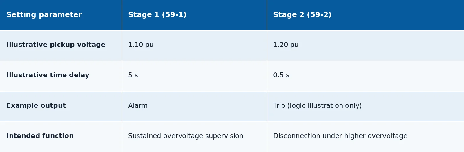
These values demonstrate the operating principle of a two-stage scheme and are not general engineering recommendations.
Actual pickup thresholds and time delays must be determined from the protected equipment’s voltage withstand capability and the applicable protection requirements.
5.3 Time-Delay Coordination
Where time grading is required, the following relationship may be used:
\[ \boxed{ t_{\mathrm{up}}\ge t_{\mathrm{down}}+\Delta t } \]
Where:
- \(t_{\mathrm{up}}\): Upstream protection delay.
- \(t_{\mathrm{down}}\): Downstream protection delay.
- \(\Delta t\): Coordination time margin.
For example, if the downstream delay is 0.5 s and an illustrative coordination margin of 0.3 s is required:
\[ t_{\mathrm{up}}\ge0.5+0.3 \]
\[ \boxed{ t_{\mathrm{up}}\ge0.8\ \mathrm s } \]
- However, overvoltage is often a system-wide condition and does not necessarily exhibit the same upstream/downstream selectivity as overcurrent protection.
- Consequently, overcurrent protection time-grading principles should not be applied mechanically to overvoltage protection.
- Operating delays should be coordinated with equipment voltage withstand limits, AVR response, reactive power control and other relevant protection functions.
6. Reset Ratio, Hysteresis and Reset Voltage Calculations
6.1 Purpose of the Reset Ratio
The reset ratio describes the relationship between the pickup threshold and the voltage at which the protection element resets.
For a typical overvoltage protection element:
\[ \boxed{ U_{\mathrm{reset}}<U_{\mathrm{set}} } \]
The reset ratio is defined as:
\[ \boxed{ K_{\mathrm r}= \frac{U_{\mathrm{reset}}} {U_{\mathrm{set}}} } \]
Therefore, typically:
\[ \boxed{K_{\mathrm r}<1} \]
Where:
- \(U_{\mathrm{reset}}\): Reset voltage.
- \(U_{\mathrm{set}}\): Pickup voltage.
- \(K_{\mathrm r}\): Reset ratio.
A suitable difference between the pickup and reset thresholds provides hysteresis, reducing repeated pickup and reset when the measured voltage fluctuates near the pickup setting.
For undervoltage protection (ANSI 27), the reset voltage is normally higher than the pickup voltage.
Using the same definition, the reset ratio for undervoltage protection is therefore typically greater than 1.
6.2 Reset Voltage and Hysteresis Calculation
The reset voltage is calculated as:
\[ \boxed{ U_{\mathrm{reset}}= K_{\mathrm r}\times U_{\mathrm{set}} } \]
Assume:
- Pickup voltage: 121 V.
- Reset ratio: 0.98.
Then:
\[ U_{\mathrm{reset}}=121\times0.98 \]
\[ \boxed{ U_{\mathrm{reset}}=118.58\ \mathrm V } \]
Under these assumptions:
- The pickup condition is satisfied when the measured voltage exceeds 121 V.
- The reset condition is satisfied when the measured voltage falls below approximately 118.58 V.
- The difference between the pickup and reset thresholds constitutes the voltage hysteresis.
The hysteresis magnitude is:
\[ \boxed{ \Delta U=U_{\mathrm{set}}-U_{\mathrm{reset}} } \]
Substituting the values:
\[ \Delta U=121-118.58 \]
\[ \boxed{ \Delta U=2.42\ \mathrm V } \]
Expressed as a percentage of the pickup voltage:
\[ \boxed{ H= \frac{\Delta U}{U_{\mathrm{set}}} \times100\% } \]
\[ H=\frac{2.42}{121}\times100\% \]
\[ \boxed{H=2\%} \]
- The 2.42 V hysteresis helps prevent repeated pickup and reset when the measured voltage fluctuates near the pickup threshold.
- Actual reset ratios, hysteresis characteristics and reset logic depend on the relay design and configuration.
6.3 Reset Ratio and Operating Stability
- If the reset ratio is too close to 1, the difference between the pickup and reset thresholds becomes small.
- Voltage fluctuations near the pickup threshold may then cause repeated pickup and reset.
- Conversely, excessive hysteresis may delay resetting after the system voltage has recovered.
- The reset ratio should therefore be selected with reference to expected voltage fluctuations, measurement accuracy and operating requirements.
7. VT Circuit Supervision and Overvoltage Protection Blocking
7.1 Effects of VT Circuit Abnormalities
Overvoltage protection relies on accurate VT secondary voltage measurements.
Faults in VT primary fuses, secondary fuses, miniature circuit breakers or measurement circuits may cause the relay to receive incorrect voltage information.
Typical abnormalities include:
- Loss of one or more phase-voltage signals.
- VT secondary circuit disconnection.
- Loose voltage circuit connections.
- Voltage signal unbalance.
- Measurement circuit abnormalities.
Such conditions may affect voltage measurement accuracy and protection decisions.
7.2 VT Circuit Supervision
- Some digital protection relays provide VT circuit supervision or voltage circuit failure detection.
- Depending on the relay design, these functions may use combinations of three-phase voltages, negative-sequence voltage, current measurements and circuit-breaker status to identify abnormalities.
- The detection criteria depend on the relay’s hardware and protection algorithms.
7.3 Overvoltage Protection Blocking Logic
Where VT circuit supervision is supported, the following functions may be configured according to the protection scheme:
- VT circuit failure alarm.
- Voltage measurement circuit abnormality indication.
- Blocking of selected voltage-dependent protection elements.
- Automatic or manual reset following voltage restoration.
A VT circuit failure does not necessarily require all ANSI 59 protection elements to be blocked.
Different voltage protection functions may respond differently to VT circuit abnormalities.
Blocking requirements for ANSI 59, 59N and 47 should therefore be assessed individually to avoid unnecessary loss of protection.
8. Coordination with Other Protection Functions
Overvoltage protection is often used alongside other voltage, frequency and current protection functions.
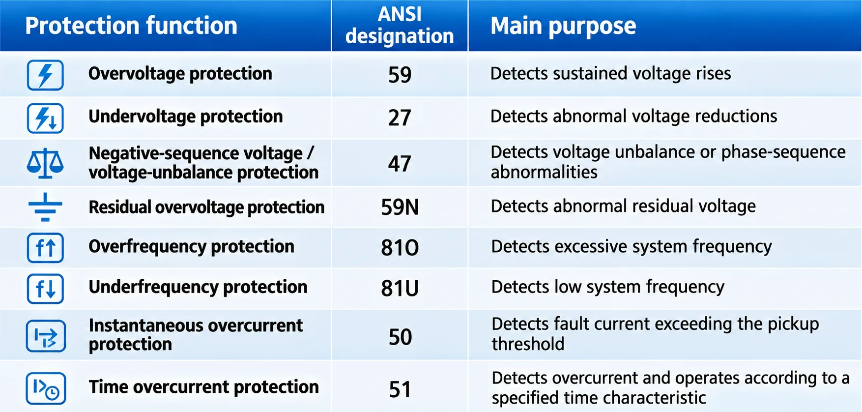
Each protection function uses different measured quantities and operating criteria.
Protection functions should be selected according to the protected equipment and system operating conditions to avoid conflicting logic or unnecessary duplication.
9. Overvoltage Protection Setting Example for an 11 kV System
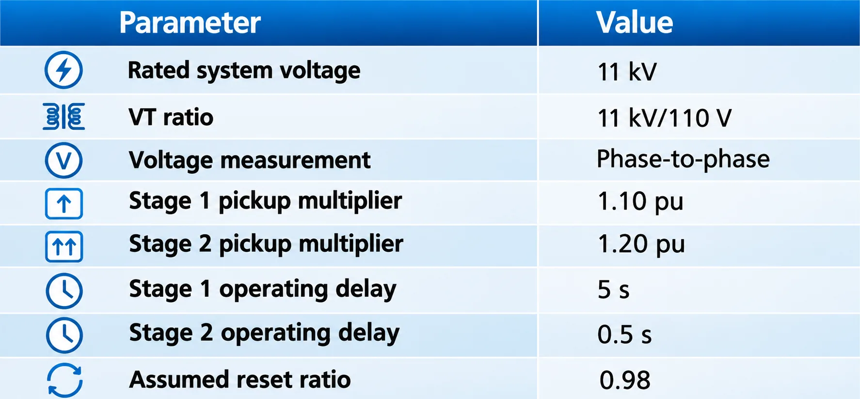
The following example demonstrates the calculation of a two-stage overvoltage protection scheme for an 11 kV distribution system.
9.1 Given Parameters
This example is intended solely to demonstrate the calculation method and does not represent recommended field settings.
9.2 Stage 1 Overvoltage Setting Calculation
Primary-side pickup voltage:
\[ U_{\mathrm{59-1,pri}}=11\times1.10 \]
\[ \boxed{ U_{\mathrm{59-1,pri}}=12.10\ \mathrm{kV} } \]
Secondary-side pickup voltage:
\[ U_{\mathrm{59-1,sec}}=110\times1.10 \]
\[ \boxed{ U_{\mathrm{59-1,sec}}=121\ \mathrm V } \]
Reset voltage:
\[ U_{\mathrm{reset,1}}=121\times0.98 \]
\[ \boxed{ U_{\mathrm{reset,1}}=118.58\ \mathrm V } \]
In this example, Stage 1 is assumed to provide an alarm after a 5 s delay.
9.3 Stage 2 Overvoltage Setting Calculation
Primary-side pickup voltage:
\[ U_{\mathrm{59-2,pri}}=11\times1.20 \]
\[ \boxed{ U_{\mathrm{59-2,pri}}=13.20\ \mathrm{kV} } \]
Secondary-side pickup voltage:
\[ U_{\mathrm{59-2,sec}}=110\times1.20 \]
\[ \boxed{ U_{\mathrm{59-2,sec}}=132\ \mathrm V } \]
Reset voltage:
\[ U_{\mathrm{reset,2}}=132\times0.98 \]
\[ \boxed{ U_{\mathrm{reset,2}}=129.36\ \mathrm V } \]
Stage 2 is assumed to illustrate a trip output with a 0.5 s delay.
This is a calculation and logic example only, not a recommended trip threshold.
9.4 Two-Stage Overvoltage Setting Results
The following values are based on the stated assumptions and must not be used directly as field protection settings.
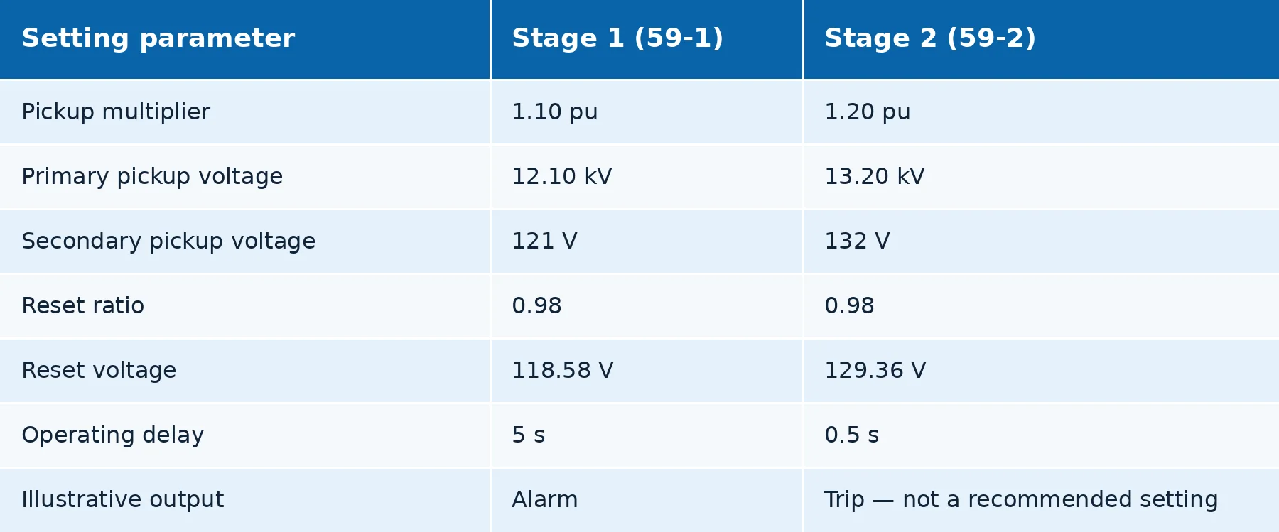
- Important: The Stage 2 pickup value of 1.20 pu corresponds to 13.20 kV, which exceeds the 12 kV highest voltage for equipment commonly associated with 11 kV installations.
- The value is retained solely to illustrate the calculation method.
- Actual pickup thresholds and operating delays must be determined from the equipment’s voltage withstand characteristics, applicable standards and protection coordination requirements.
9.5 Verification Against the Highest Voltage for Equipment
For many 11 kV medium-voltage installations, the highest voltage for equipment, \(U_m\), is 12 kV.
The applicable value must be confirmed against the equipment nameplate and relevant standards.
For the illustrative Stage 2 setting:
\[ U_{\mathrm{59-2,pri}}=11\times1.20 \]
\[ \boxed{ U_{\mathrm{59-2,pri}}=13.20\ \mathrm{kV} } \]
This calculated value exceeds the 12 kV equipment voltage class.
The highest voltage for equipment (\(U_m\)) is a reference parameter used in equipment voltage ratings and insulation coordination. It is not, by itself, a criterion for determining an overvoltage protection pickup or trip setting.
- The overvoltage protection threshold must be established independently, taking into account the equipment’s permissible operating voltage, voltage withstand characteristics, expected overvoltage duration, system operating conditions and applicable protection requirements.
- Therefore, exceeding \(U_m\) does not automatically define the required relay trip threshold or permissible operating time.
- The final pickup voltage and operating delay must be verified against the protected equipment’s characteristics, applicable standards and protection coordination requirements.
10. Conclusion
An overvoltage protection relay monitors system voltage, compares the measured value with predefined pickup thresholds and applies time-delay logic to detect sustained overvoltage conditions.
The principal setting calculations include the following.
Voltage pickup setting
\[ \boxed{ U_{\mathrm{set}}= K_{\mathrm{set}}\times U_{\mathrm n} } \]
Preliminary setting based on maximum normal operating voltage
\[ \boxed{ U_{\mathrm{set}}\ge K_{\mathrm{rel}}\times U_{\mathrm{max,normal}} } \]
VT secondary pickup voltage
\[ \boxed{ U_{\mathrm{set,sec}}= \frac{U_{\mathrm{set,pri}}}{K_{\mathrm{VT}}} } \]
Reset voltage
\[ \boxed{ U_{\mathrm{reset}}= K_{\mathrm r}\times U_{\mathrm{set}} } \]
Hysteresis magnitude
\[ \boxed{ \Delta U= U_{\mathrm{set}}-U_{\mathrm{reset}} } \]
Approximate total operating time (illustrative, non-standard decomposition)
\[ \boxed{ t_{\mathrm{total}}\approx t_{\mathrm{detect}}+ t_{\mathrm{set}}+ t_{\mathrm{output}} } \]
- For 33 kV and 11 kV distribution systems, overvoltage protection settings should be verified against normal operating voltage ranges, equipment voltage withstand capabilities, VT measurement configurations, reset characteristics, operating delays and coordination with other protection functions.
- Mathematical setting examples must be distinguished from actual engineering settings to avoid applying unverified pickup multipliers directly to operating equipment.
- Appropriate voltage thresholds, operating delays and blocking logic contribute to dependable overvoltage protection and safe power system operation.


