Capacitor Bank Current Unbalance Protection (ANSI 60): Operating Principle, Functions and Setting Calculations
I. Operating Principle of Capacitor Bank Current Unbalance Protection (ANSI 60)
- A capacitor bank typically consists of multiple capacitor units connected in series and parallel. Under healthy operating conditions, the current in the designated unbalance measuring circuit is normally small. Manufacturing tolerances, supply voltage unbalance and measuring errors may nevertheless produce a standing unbalance current.
- If an internal capacitor element fails short-circuit, an internal fuse disconnects a faulty element, or an external fuse disconnects a capacitor unit, the equivalent capacitance of the affected branch changes. This alters the magnitude and phase angle of the unbalance current.
- For a double-wye configuration, a dedicated current transformer (CT) can measure the current flowing through the connection between the two star points. For a bridge configuration, the current in the bridge branch can be measured. The measuring arrangement must correspond to the actual capacitor bank connection and protection design.
- The relay measures the current through a dedicated unbalance current input, \(i_{\mathrm{unb}}\). With the protection enabled, operation occurs when the measured current reaches or exceeds the pickup setting and the condition persists for the set operating time delay.
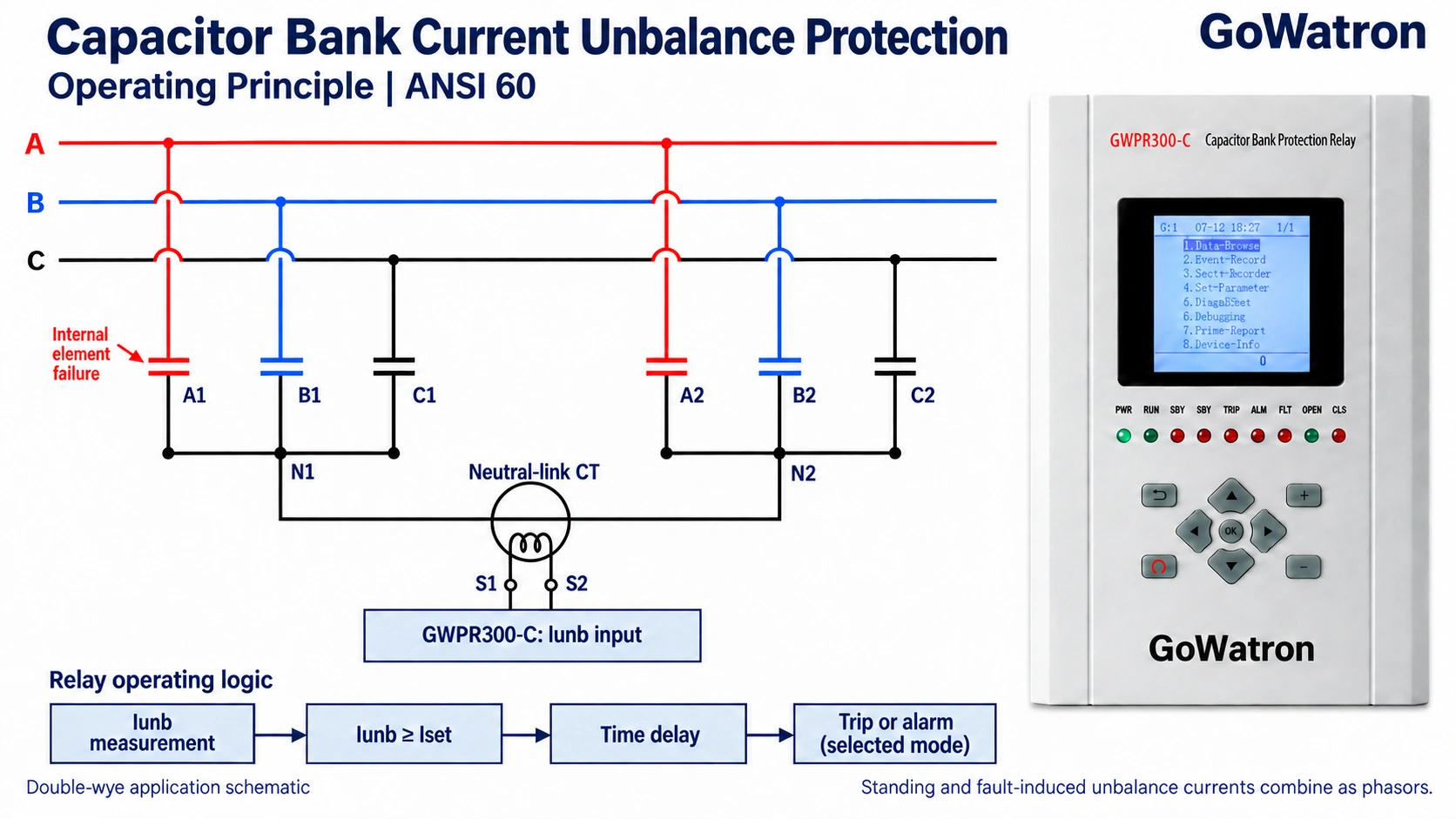
The current criterion is:
\[ i_{\mathrm{unb}}\geq I_{\mathrm{unb,set}} \]
The duration criterion is:
\[ t\geq t_{\mathrm{set}} \]
where:
- \( i_{\mathrm{unb}} \) is the measured unbalance current magnitude;
- \( I_{\mathrm{unb,set}} \) is the unbalance overcurrent pickup setting;
- \( t_{\mathrm{set}} \)is the operating time delay.
- The supplied instruction manual describes one unbalance overcurrent stage, configurable for either tripping or alarm operation.
- This article uses ANSI 60 as the functional classification for capacitor bank current unbalance protection; the device designation used on project drawings and setting sheets should be confirmed against the manufacturer’s documentation. Application designations such as 60N and 60P depend on the actual measuring arrangement and the manufacturer’s function definitions.
- The dedicated unbalance current must not be confused with the negative-sequence current calculated from the three phase currents.
II. Functions of Capacitor Bank Current Unbalance Protection (ANSI 60)
1. Detecting Internal Asymmetrical Faults
- Capacitor element failures and fuse operations can change the capacitance of the affected branch. Current unbalance protection detects the resulting changes in the designated measuring circuit.
- Detection of a single element or unit failure is not guaranteed. Sensitivity depends on bank construction, fault location, standing unbalance, CT performance and relay measuring capability.
2. Preventing Fault Escalation
- Element short circuits and fuse operations can redistribute voltage within capacitor units and across series groups. Some healthy elements or units may consequently be subjected to excessive voltage.
- The trip threshold and total clearing time must prevent the applicable equipment voltage–time withstand limits from being exceeded.
- Faults in different locations may produce partially cancelling unbalance currents. The number of failed elements alone is therefore insufficient to establish either the measured current or the severity of internal overvoltage.
3. Providing Time-Delayed Alarm or Tripping
- The documented stage can be configured to issue an alarm or initiate tripping when its current and duration criteria are satisfied.
- In alarm mode, the stage provides an indication requiring an appropriate operational response. In tripping mode, it initiates capacitor bank disconnection through the configured trip circuit.
- Some relays provide separate alarm and trip stages with independent settings. These functions must be verified for the actual relay rather than assumed. The supplied manual documents one stage with a selectable alarm or trip output.
III. Setting Calculations for Capacitor Bank Current Unbalance Protection (ANSI 60)
- Before calculating settings, specify the required detection objective. This may be early warning of a specified element or unit failure, or automatic disconnection before an applicable internal voltage–time withstand limit is exceeded.
- Alarm and trip objectives require separate sensitivity assessments. An alarm setting is intended to detect the specified warning condition; a trip setting must provide timely disconnection for the assessed dangerous conditions.
- The documented stage cannot provide two independent thresholds simultaneously. If both objectives are required, additional independently configurable protection must be provided and verified.
The calculation sequence is:
- Determine the maximum healthy-state unbalance current and the minimum total current for the conditions requiring operation.
- Complete the feasibility assessment.
- Select a pickup setting only if the feasibility requirements are satisfied.
- Calculate and verify the operating time delay.
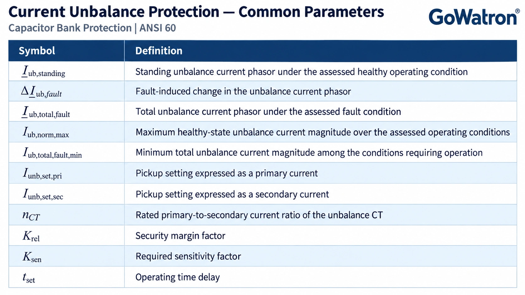
1. Common Parameters
2. Unbalance Overcurrent Pickup Setting
Calculate the electrical conditions for the actual bank connection, internal series-parallel arrangement and fuse configuration.
For each assessed fault, determine:
- The voltages across the remaining healthy elements or units;
- The total unbalance current measured by the relay;
- Whether the condition requires an alarm or automatic disconnection;
- The applicable voltage–time withstand limits.
At a given operating condition:
\[ \underline{I}_{\mathrm{ub,total,fault}} = \underline{I}_{\mathrm{ub,standing}} + \Delta\underline{I}_{\mathrm{ub,fault}} \]
The relay responds to the magnitude:
\[ I_{\mathrm{ub,total,fault}} = \left| \underline{I}_{\mathrm{ub,standing}} + \Delta\underline{I}_{\mathrm{ub,fault}} \right| \]
Equivalently:
\[ I_{\mathrm{ub,total,fault}} = \sqrt{ I_{\mathrm{ub,standing}}^2 + |\Delta\underline{I}_{\mathrm{ub,fault}}|^2 + 2I_{\mathrm{ub,standing}} |\Delta\underline{I}_{\mathrm{ub,fault}}| \cos\phi } \]
- where \( \phi \)is the angle between the standing unbalance current and the fault-induced change.
- Depending on this angle, the measured current may increase or decrease following a fault. Fault progression must not be assumed to produce a continuously increasing current magnitude.
Determine the minimum total measured current among the conditions requiring operation:
\[ I_{\mathrm{ub,total,fault,min}} = \min_{\text{assessed conditions}} \left| \underline{I}_{\mathrm{ub,standing}} + \Delta\underline{I}_{\mathrm{ub,fault}} \right| \]
After determining this value and\( I_{\mathrm{ub,norm,max}} \), complete the feasibility assessment before selecting the primary pickup setting.
A feasible setting requires:
\[ K_{\mathrm{rel}}I_{\mathrm{ub,norm,max}} < \frac{I_{\mathrm{ub,total,fault,min}}}{K_{\mathrm{sen}}} \]
- The factors \(K_{\mathrm{rel}}\) and \(K_{\mathrm{sen}}\) must be selected from the applicable project or utility protection setting requirements and manufacturer guidance, where specified. If no numerical values are prescribed, justify the margins through a documented assessment of operating variations, modelling uncertainties, CT errors and relay performance. They must not be selected arbitrarily.
- No universal numerical range is assigned in this article. General capacitor bank protection guidance, including IEEE C37.99, should be applied together with the actual equipment data; it should not be assumed to prescribe fixed values for these particular factors.
If the feasibility condition is satisfied, select the primary pickup setting within the following interval:
\[ K_{\mathrm{rel}}I_{\mathrm{ub,norm,max}} < I_{\mathrm{unb,set,pri}} \leq \frac{I_{\mathrm{ub,total,fault,min}}}{K_{\mathrm{sen}}} \]
Notes:
- The lower limit provides security during healthy operation;
- The upper limit provides sensitivity to the required fault conditions;
- The fault-current term is the total measured current, not merely the fault-induced increment;
- Measuring errors and uncertainty margins must be included consistently, without double counting.
If the feasibility condition is not satisfied, stop pickup-setting selection for the proposed arrangement. No threshold can meet both requirements for the assessed conditions, and the protection design must be reassessed.
Some phasor cancellation does not automatically invalidate the scheme. The decisive question is whether adequate security and sensitivity remain after cancellation and measuring uncertainties are included.
Changing the CT ratio alone cannot remove an overlap between healthy-state and fault-state primary currents. Adjusting the time delay cannot make a below-pickup current operate the stage.
Possible design measures include reducing standing unbalance, changing bank grouping or the measuring arrangement, or selecting another protection principle. Voltage differential protection or validated standing-unbalance compensation may be suitable for some configurations, but each alternative requires a separate feasibility assessment.
Convert a suitable primary pickup setting to its secondary equivalent:
\[ I_{\mathrm{unb,set,sec}} = \frac{I_{\mathrm{unb,set,pri}}}{n_{\mathrm{CT}}} \]
Confirm that the result lies within the relay’s setting range and validated measuring capability.
3. Operating Time-Delay Setting
Select the operating time delay to:
- Ride through relevant switching and external-fault transients;
- Coordinate with fuse operation where applicable;
- Coordinate with other protection functions;
- Disconnect the bank within its applicable voltage–time withstand limits;
- Address credible fault escalation before equipment damage occurs.
For each assessed fault condition \( j \):
\[ t_{\mathrm{set}}+t_{\mathrm{out}}+t_{\mathrm{CB}} \leq t_{\mathrm{allow},j} \]
where:
- \( t_{\mathrm{out}} \)is the additional relay processing and output time not included in the set delay;
- \( t_{\mathrm{CB}} \) is the circuit-breaker clearing time;
- \( t_{\mathrm{allow},j} \)is the permissible duration for the voltages and equipment conditions associated with fault case\( j \)
The permissible duration is condition-dependent. Establish it from the relevant equipment withstand data rather than using one universal value.
For a fixed definite-time stage, verify all relevant fault cases and identify the most restrictive coordination requirement. This is not necessarily the case with the largest measured unbalance current.
Where successive failures can change the internal voltage during the operating delay, assess credible fault progression as well as individual steady-state cases. Use the manufacturer’s applicable withstand and fault-progression information; do not assume a universal failure rate.
If a fixed delay cannot both ride through the required transients and clear credible faults sufficiently quickly, revise the protection configuration or principle. A slowly developing fault does not, by itself, justify a longer delay once a damaging condition has been reached.
In alarm mode, the delay determines alarm initiation only. Any reliance on subsequent operator action must be assessed separately and must not replace required automatic tripping.
IV. Practical Considerations for Applying Capacitor Bank Current Unbalance Protection (ANSI 60)
1. CT Ratio and Input Circuit
Connect the measuring CT to the dedicated \(i_{\mathrm{unb}}\) input in accordance with the protection design.
Distinguish this circuit from the residual current input and the three-phase protection current inputs. Verify CT location, ratio, secondary wiring and measuring performance.
The supplied manual lists a pickup setting range of 0.1–100 A and a time-delay range of 0–100 s. These are available setting ranges, not recommended site settings. Confirm the current reference, rated input and measuring performance for the actual hardware version.
2. Standing Unbalance and Measuring Errors
Record representative measurements with the bank confirmed to be healthy. Include the expected operating range rather than relying on a single measurement.
Standing unbalance is the measured healthy-state baseline under specified conditions; it is not necessarily constant under all operating conditions.
Assess its phase relationship with fault-induced changes. Do not simply add their magnitudes or assume that every fault increases the measured current.
The supplied manual does not document standing-unbalance compensation, percentage restraint or accumulated failed-element counting for this function. These capabilities must not be assumed when setting the relay.
3. Operating Mode and Commissioning Checks
Before enabling the protection, verify:
- The CT measuring location, ratio and secondary wiring;
- The input channel and displayed current;
- The pickup setting and operating time delay;
- The protection enable status;
- The selected alarm or tripping objective and operating mode;
- Any separately provided alarm and trip functions;
- The output circuits, signalling and reset requirements;
- The agreed function designation on drawings and setting sheets.
Use secondary injection testing to verify pickup, timing and output logic. Where practicable, include test currents representing the calculated total current after phasor cancellation.
Secondary injection verifies relay behaviour. It does not replace the bank fault calculations or demonstrate that the overall protection scheme has adequate sensitivity.
Reset signals, indications and display messages as required by the instruction manual.
V. Summary of Capacitor Bank Current Unbalance Protection (ANSI 60)
The documented function measures a dedicated unbalance current and operates when its magnitude reaches the pickup setting for the specified time delay. One stage is configurable for either alarm or tripping operation.
Setting calculations comprise two steps:
- Establish whether a secure and sensitive pickup setting exists for the specified detection objective, including standing unbalance, phasor cancellation and measuring uncertainties. Select a pickup setting only after this feasibility assessment has passed.
- Select and verify the operating delay against transient requirements, fuse coordination, condition-dependent withstand limits and credible fault escalation.
Alarm and trip objectives are different. If both are required, the installed protection must provide the necessary independent functions.
If no suitable pickup or time-delay setting exists, revise the protection scheme rather than continuing to adjust settings within an infeasible arrangement.
An actual calculation requires the bank connection diagram, internal construction, fuse configuration, rated capacitance and voltage, CT data, representative healthy-state measurements, equipment withstand characteristics and relevant manufacturer guidance on fault progression.


