What Are Positive-, Negative- and Zero-Sequence Currents?
In power systems, positive-, negative- and zero-sequence currents are components used to analyse unbalanced three-phase conditions. They are derived using the method of symmetrical components, introduced by Charles LeGeyt Fortescue.
Basic Principle
Any set of three-phase current phasors at the same frequency can be uniquely decomposed into three sets of symmetrical components:
- Positive-sequence components
- Negative-sequence components
- Zero-sequence components
Each phase current is the phasor sum of its three sequence components:
\[ I_a=I_{a1}+I_{a2}+I_{a0} \]
\[ I_b=I_{b1}+I_{b2}+I_{b0} \]
\[ I_c=I_{c1}+I_{c2}+I_{c0} \]
The subscripts 1, 2 and 0 denote positive-, negative- and zero-sequence components, respectively.
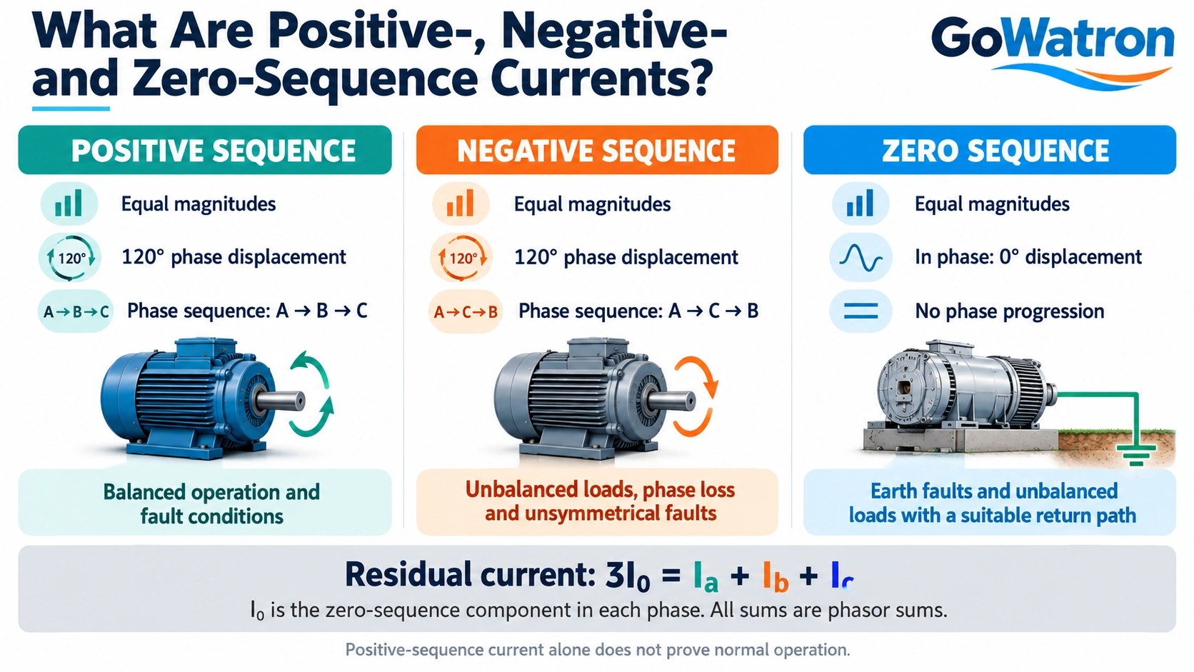
1. Positive-Sequence Current
Positive-sequence currents have the following characteristics:
- The three phase components have equal magnitudes.
- They are displaced from one another by 120°.
- Their phase sequence is A → B → C, matching the normal system phase sequence.
Taking the A-phase positive-sequence current as the reference:
\[ I_{a1}=I_1\angle0^\circ \]
\[ I_{b1}=I_1\angle-120^\circ \]
\[ I_{c1}=I_1\angle+120^\circ \]
During normal balanced three-phase operation, the fundamental-frequency currents contain only positive-sequence components. However, positive-sequence current also exists during faults. For example, a symmetrical three-phase short circuit contains only positive-sequence current.
Therefore, the presence of positive-sequence current alone does not indicate that the system is operating normally.
2. Negative-Sequence Current
Negative-sequence currents have the following characteristics:
- The three phase components have equal magnitudes.
- They are displaced from one another by 120°.
- Their phase sequence is A → C → B, opposite to the normal system phase sequence.
Taking the A-phase negative-sequence current as the reference:
\[ I_{a2}=I_2\angle0^\circ \]
\[ I_{b2}=I_2\angle+120^\circ \]
\[ I_{c2}=I_2\angle-120^\circ \]
Negative-sequence current commonly occurs under the following conditions:
- Unsymmetrical short-circuit faults.
- Open-conductor or phase-loss conditions.
- Unbalanced three-phase loads.
- Current unbalance due to an unbalanced supply voltage.
In rotating electrical machines, negative-sequence current produces a magnetic field that rotates in the opposite direction to the positive-sequence field. This can cause:
- Additional losses and overheating in motors and generators.
- Torque pulsations.
- Reduced operating efficiency.
Negative-sequence current is therefore an important operating quantity for machine unbalance protection.
3. Zero-Sequence Current
Zero-sequence currents have the following characteristics:
- The three phase components have equal magnitudes.
- They are in phase, with a phase displacement of 0°.
- There is no phase progression between A, B and C.
Taking the zero-sequence current angle as the reference:
\[ I_{a0}=I_{b0}=I_{c0}=I_0\angle0^\circ \]
When consistent current reference directions are used, the three zero-sequence components have equal instantaneous values and flow in the same direction at any given instant. This describes the zero-sequence components, rather than the total three-phase currents.
Zero-Sequence Current Paths
Whether zero-sequence current can flow depends on the availability of a suitable closed circuit.
For a three-phase line, the return path may include:
- A neutral conductor.
- An earthing conductor.
- The earth.
- A circuit formed through phase-to-earth capacitances.
Zero-sequence current can also circulate within a delta-connected winding, but this component does not appear in the external line currents on the delta side.
Common Conditions Producing Zero-Sequence Current
- Single-phase-to-earth faults.
- Two-phase-to-earth faults.
- Unbalanced three-phase loads with a neutral conductor or another suitable zero-sequence return path.
In a system with an unearthed neutral, zero-sequence current is zero during ideal balanced normal operation. During an earth fault, however, phase-to-earth capacitances can provide a return path, allowing zero-sequence current to flow in the relevant circuits.
An unearthed neutral does not necessarily mean that zero-sequence current is absent during an earth fault.
Relationship Between Zero-Sequence Current and Residual Current
\[ I_0=\frac{I_a+I_b+I_c}{3} \]
\[ 3I_0=I_a+I_b+I_c \]
These equations use phasor sums:
\( I_0 \)is the zero-sequence current component in each phase.
\( 3I_0 \) is the residual current, equal to the phasor sum of the three phase currents.
For protection relay measurements, displays and settings, it is essential to identify whether the quantity is \(I_0\) or \(3I_0\), as they differ by a factor of three.
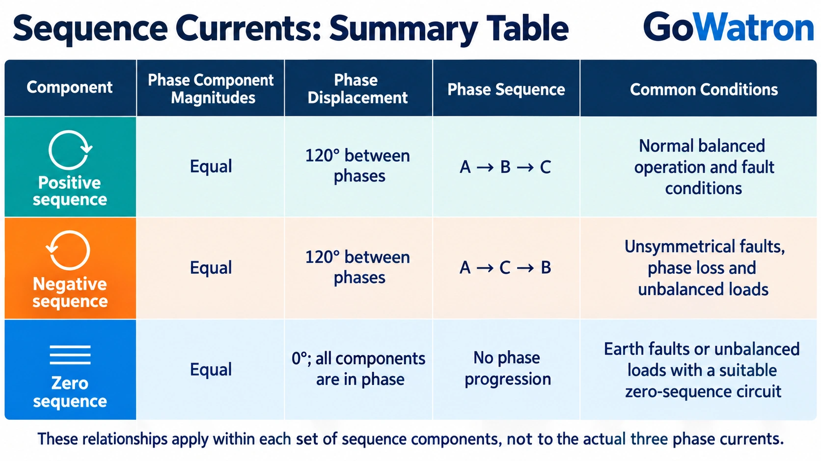
4. Summary Table
The magnitude and phase relationships in this table apply within each set of sequence components. They do not imply that the actual three phase currents are equal.
5. Why Are Sequence Components Important?
The method of symmetrical components allows engineers to:
- Analyse unsymmetrical faults using sequence equivalent networks.
- Use quantities such as negative- and zero-sequence currents to support fault detection and protection operation.
- Assess the effects of three-phase unbalance on motors and generators.
- Evaluate the negative-sequence withstand capability of rotating electrical machines.
Sequence components provide important information for analysis and protection. In practice, fault identification usually also considers voltage, current direction, system earthing arrangements and protection logic.
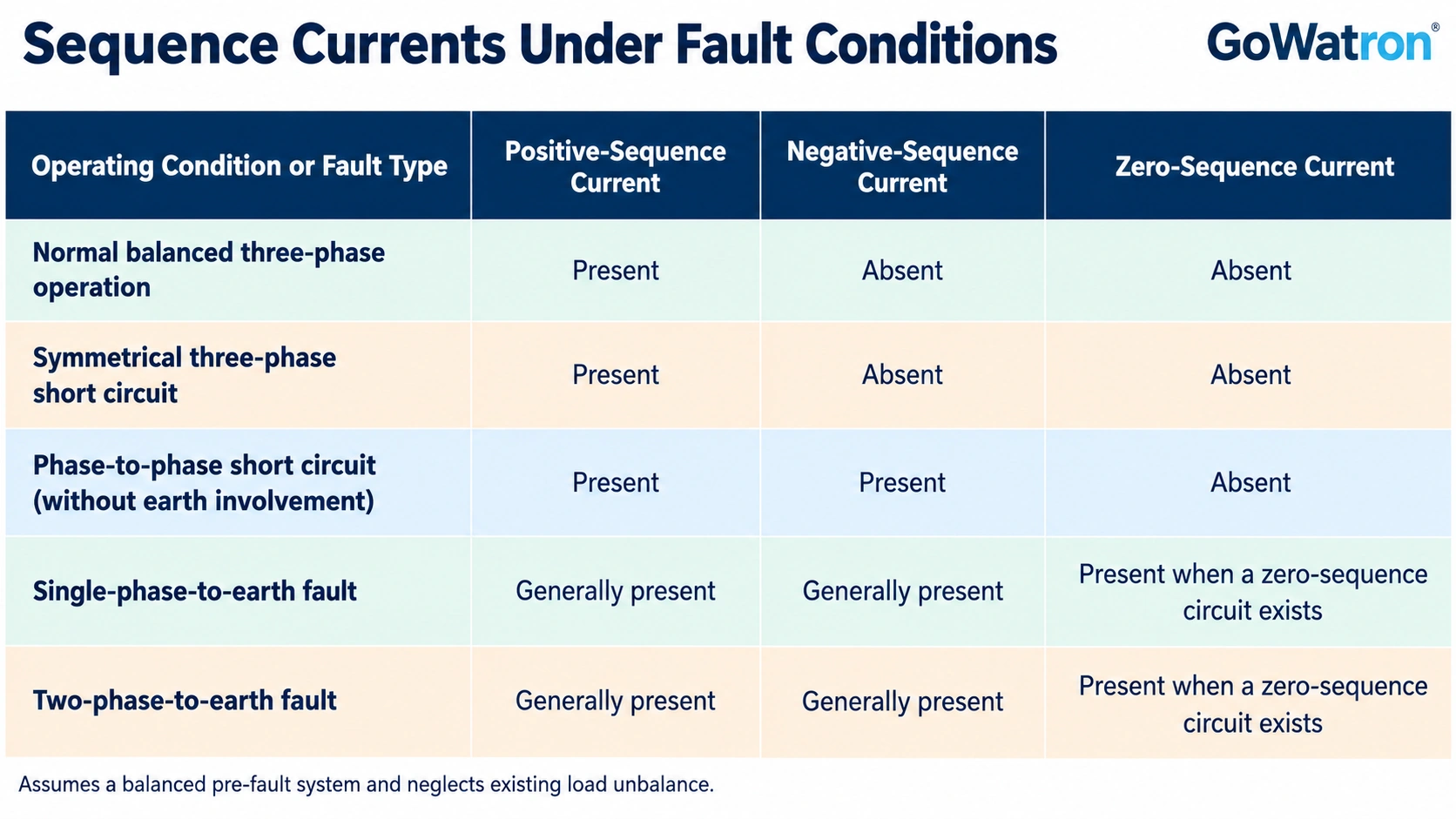
6. Sequence Currents Under Typical Operating and Fault Conditions
The following relationships apply to conventional fundamental-frequency fault analysis, assuming a balanced pre-fault system and neglecting existing load unbalance:
For an A-phase-to-earth fault, the sequence currents in the fault branch satisfy:
\[ I_1=I_2=I_0 \]
Therefore:
\[ I_f=3I_0 \]
Here, \( I_f \) is the earth-fault current in the fault branch. These relationships apply to the fault branch and should not be directly applied to total current measurements at arbitrary locations in the system.
Whether zero-sequence current can be measured elsewhere in the system, and its magnitude, depends on the earthing arrangement, transformer winding connections, available zero-sequence circuits and measurement location.


