Zero-Sequence Overcurrent Protection Relays (ANSI 50N/51N/67N): Operating Principles, Applications and Setting Calculations
- Zero-sequence overcurrent protection relays are important protective devices used to detect earth faults in power systems. Common function designations include 50N (instantaneous earth-fault overcurrent), 51N (time-delayed earth-fault overcurrent) and 67N (directional earth-fault overcurrent). Residual current is measured directly using a core-balance current transformer or calculated from the three measured phase currents. The relay issues a trip or alarm when the applicable current threshold, operating-time and directional conditions are satisfied.
- 50N, 51N and 67N differ in their operating-time characteristics, directional discrimination and applications. All three functions may be integrated into a single numerical protection relay. The suffixes N (neutral) and G (ground) are commonly used in neutral-current and earth-fault protection designations. Their use and association with particular measurement arrangements may vary between manufacturers. The actual function definitions should therefore be checked against the relay manual.
I. Operating Principles of Zero-Sequence Overcurrent Protection Relays
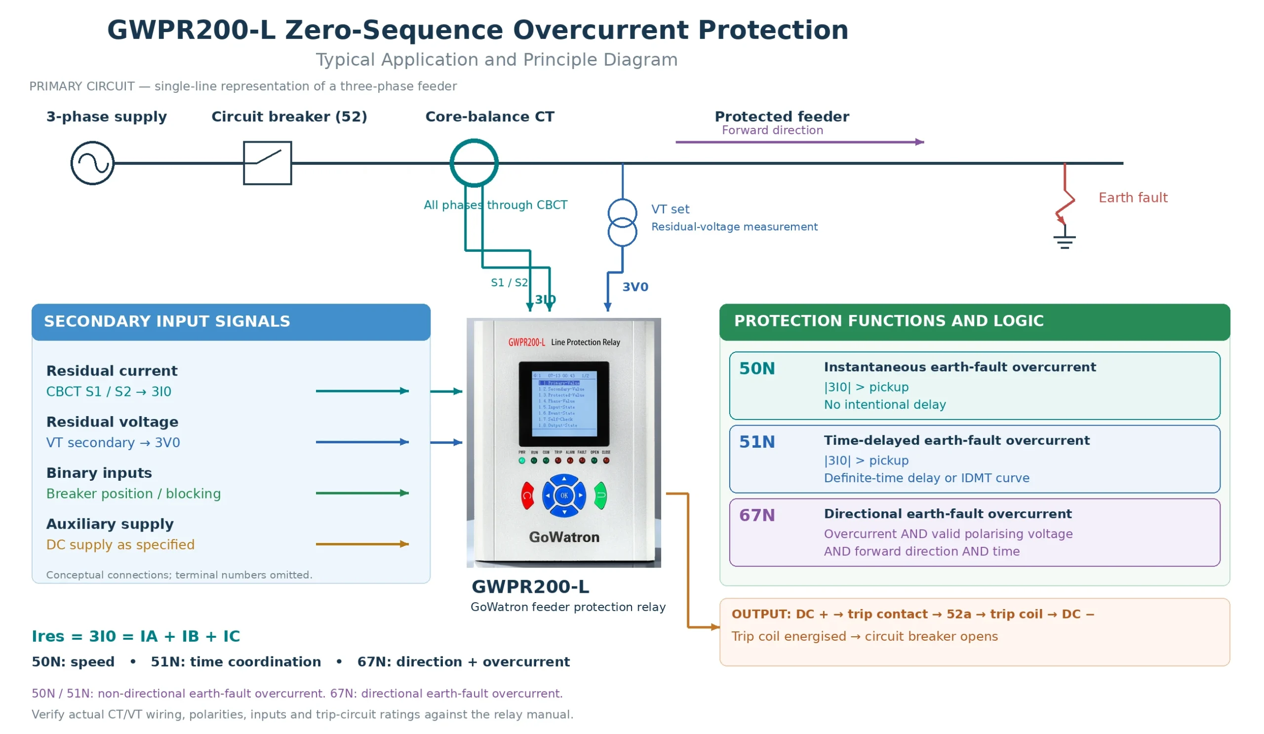
Zero-sequence overcurrent protection is based on the phasor sum of the three phase currents and the symmetrical-component relationships. Under ideal balanced three-phase operating conditions, the phase-current phasor sum is zero:
\[ I_A+I_B+I_C=0 \]
The zero-sequence current component is defined as:
\[ I_0=\frac{I_A+I_B+I_C}{3} \]
The residual current is:
\[ I_{\mathrm{res}}=3I_0=I_A+I_B+I_C \]
- Here, \( I_A \), \( I_B \) and \( I_C \) are the phase-current phasors; \( I_0 \)is the zero-sequence current component; and\( I_{\mathrm{res}} \)is the residual current, equal to three times the zero-sequence current.
- A single-phase-to-earth or two-phase-to-earth fault may produce residual current at the relay location if a zero-sequence current path exists. A non-directional earth-fault overcurrent function operates when the residual current exceeds its pickup setting and the operating-time condition is satisfied. A directional earth-fault overcurrent function additionally requires the directional criterion to be satisfied.
- In practice, residual current during normal operation, CT ratio and phase-angle errors, CT saturation and transient conditions can affect the measured quantity. Unbalanced loads in a three-phase four-wire system may also produce neutral current during normal operation. Consequently, the presence of measured zero-sequence current does not, by itself, establish that an earth fault has occurred.
There are two main methods of obtaining residual current:
- Direct measurement: A core-balance current transformer (CBCT), also known as a ring-type or window-type CT, measures the sum of the currents in the conductors passing through its aperture. The routing of phase conductors, the neutral conductor and cable screen earthing conductors must follow the specified connection arrangement to prevent normal return currents or screen currents from affecting the measurement.
- Summation of phase currents: Residual current is obtained either through the residual connection of three phase CTs or by numerical summation of the three measured phase-current phasors. Differences between the phase CT characteristics and errors caused by CT saturation must be considered.
The system neutral earthing arrangement directly affects the magnitude and phase angle of zero-sequence current, as well as the appropriate protection method:
- Solidly earthed or low-resistance-earthed systems: Earth faults can generally produce sufficient fault current for non-directional or directional earth-fault overcurrent protection. The appropriate scheme depends on the network configuration and selectivity requirements.
- Unearthed systems: Earth-fault current is primarily associated with the network phase-to-earth capacitances. The magnitude and direction of residual current differ between faulted and healthy feeders, so current magnitude alone may not provide reliable faulted-feeder identification.
- Resonant-earthed systems: The inductive current supplied by the arc-suppression coil (Petersen coil) compensates for the network capacitive earth-fault current, potentially leaving only a small residual fault current. Depending on the compensation conditions, protection may require active-current, admittance-based, transient-based or other suitable earth-fault criteria. Settings developed for an unearthed system cannot simply be applied without reassessment.
The distinguishing principle of 67N—directional discrimination: The 67N function adds a directional criterion to the overcurrent criterion. Common implementations use residual current \( 3I_0 \)and residual voltage \( 3V_0 \), determining the fault-current direction from their phase relationship or from the corresponding active or reactive current components. Some relays use other polarising methods; the supported implementation must be checked against the relay manual.
For a phase-angle criterion, the following definition may be used, subject to the relay’s specified voltage polarity and current reference direction:
\[ \varphi=\arg(3I_0)-\arg(3V_0) \]
- Here, \( \arg \) denotes the phase angle of a phasor. With this definition, the current angle is measured relative to the voltage angle, and current leading voltage is positive. Other relays may define current lagging voltage as positive or use the opposite order of subtraction. The angle must therefore be interpreted or converted according to the relevant manual.
- The relay determines whether this angle lies within the configured forward operating sector. Some algorithms use\( -3V_0 \) as the polarising reference or apply active- or reactive-component criteria. The angle convention and operating sector must therefore be interpreted together with the relay’s definitions.
- For phase-angle-based implementations, the operating sector is commonly defined relative to the relay characteristic angle (RCA). The available settings and angle conventions depend on the relay.
- The relay characteristic angle, operating sector, minimum polarising threshold and forward/reverse definitions must be selected according to the system earthing arrangement, fault characteristics and relay algorithm. CT and VT polarities must also be verified. The 67N function operates only when the current, polarising, directional and operating-time conditions are all satisfied.
II. Main Applications of Zero-Sequence Overcurrent Protection Relays
The primary purpose of zero-sequence overcurrent protection is to detect earth faults. Under ideal conditions, three-phase faults and phase-to-phase faults that do not involve earth do not produce zero-sequence current. Zero-sequence protection therefore provides a relatively independent means of detecting earth faults. However, discrimination between fault types does not automatically provide selectivity between all fault locations.
The main applications are:
- Earth-fault clearance: In solidly earthed or low-resistance-earthed systems, 50N/51N may provide primary or backup earth-fault protection, depending on the network configuration. Current thresholds and time coordination are used to disconnect the faulted equipment or feeder.
- Earth-fault monitoring: In unearthed or resonant-earthed systems, suitable zero-sequence protection or earth-fault feeder-selection functions can detect an earth fault and initiate an alarm or trip, as required by the operating policy. Whether operation may continue after the first earth fault depends on the applicable system operating procedures.
- Supporting the detection of abnormal operating conditions: Certain open-conductor or open-phase conditions may produce zero-sequence current. Zero-sequence protection can provide supplementary information, but it does not replace dedicated phase-loss, negative-sequence or open-phase protection.
- Directional selectivity: In ring networks, parallel circuits and multi-source systems, 67N can use fault-current direction to restrain protection functions that should not operate, improving earth-fault protection selectivity.
Zero-sequence overcurrent protection allows an independent pickup threshold to be set for earth faults. In suitable systems, it can provide good sensitivity and complement phase overcurrent protection. Under ideal symmetrical conditions, phase faults without earth involvement and balanced power swings do not directly produce zero-sequence current. Practical applications must nevertheless account for CT errors, saturation and transient residual currents.
Its main limitation is that earth-fault current is strongly influenced by the neutral earthing arrangement, network configuration, operating conditions and fault resistance. In unearthed or resonant-earthed systems, and for high-resistance earth faults, residual-current magnitude alone may not provide both adequate sensitivity and selectivity.
III. Functional Differences Between 50N, 51N and 67N
These designations identify different protection functions. They are not alternative names for the same function, nor do they necessarily represent three separate physical relays.
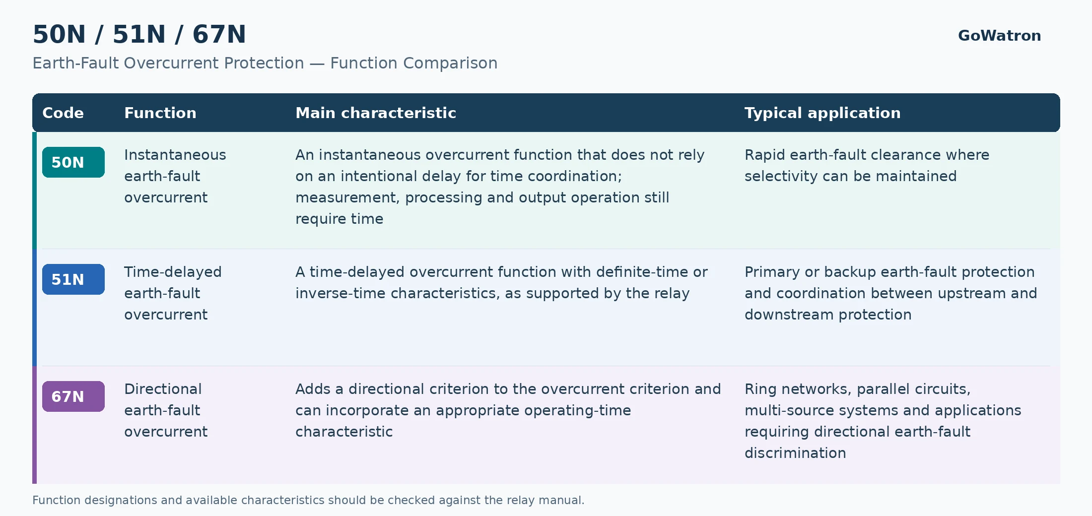
The main distinctions are the operating-time characteristics and the presence or absence of directional supervision.
- The main difference between 50N and 51N is their operating-time characteristic. The 50N function provides rapid operation, while 51N uses an intentional delay or an inverse-time curve to coordinate with upstream and downstream protection. If a particular relay provides an adjustable short delay for a function labelled 50N, that implementation should be described according to the manufacturer’s documentation.
- In staged protection schemes that use current magnitude for selectivity, 50N is commonly assigned a relatively high pickup setting to clear some internal faults rapidly. The 51N function commonly uses a lower pickup setting and an appropriate delay to extend fault coverage and provide backup protection. However, high pickup for 50N and low pickup for 51N are not mandatory rules for every application.
- Depending on the relay, 51N may offer definite-time (DT) or inverse definite minimum time (IDMT) characteristics. With a definite-time characteristic, the relay operates after a set delay once the current exceeds the pickup threshold. With an inverse-time characteristic, the operating time decreases as the fault current increases, according to the selected curve and time-setting parameters.
- The distinguishing feature of 67N is its ability to discriminate between the configured forward and reverse fault-current directions. Direction alone does not identify fault distance or distinguish between successive protection zones in the same direction. Time, curve or other forms of selectivity coordination are therefore generally still required.
- Blocking, acceleration or adjustment of earth-fault protection during auto-reclosing must be determined by the specific protection scheme. These behaviours are not inherent characteristics of 50N, 51N or 67N.
IV. Setting Calculations for Zero-Sequence Overcurrent Protection Relays
Zero-sequence overcurrent protection settings must be determined from the neutral earthing arrangement, network configuration, protection stage, CT arrangement and coordination requirements.
Before calculation, establish whether the relay setting refers to \(I_0\) or \(3I_0\), and use primary and secondary quantities consistently. The following equations use residual current \(I_{\mathrm{res}}=3I_0\). If the relay uses another quantity or a per-unit setting, conversion must follow the relay manual.
1. Basic Principles for Pickup Settings
The pickup setting must satisfy security, selectivity and sensitivity requirements. The applicable setting criteria depend on the protection stage.
(1) Allowance for Normal Residual Current and Measurement Errors
The basic requirement may be expressed as:
\[ I_{\mathrm{set,pri}} \geq K_{\mathrm{rel,n}}\,I_{\mathrm{res,normal,max}} \]
Here,\( I_{\mathrm{set,pri}} \)is the primary residual-current pickup setting; \( I_{\mathrm{res,normal,max}} \) is the maximum primary-equivalent residual current that must not cause operation under the specified normal and non-fault conditions, including relevant measurement errors; and \( K_{\mathrm{rel,n}} \)is the security margin factor used for this assessment, selected according to the applicable setting guidelines, measurement errors and engineering conditions.
The maximum normal residual current should be established by measurement, calculation or error analysis. No fixed percentage of the transformer rated current should be used as a universal assumption. Where CT saturation or transient conditions produce significant residual current, additional delay, blocking or other measures to prevent unwanted operation may be required.
(2) Coordination with Downstream Earth-Fault Protection
Where the scheme uses pickup-current grading, the relationship may be expressed as:
\[ I_{\mathrm{set,up}} \geq K_{\mathrm{co}}\,I_{\mathrm{set,down}} \]
- Here, \( I_{\mathrm{set,up}} \) and\( I_{\mathrm{set,down}} \) are the upstream and downstream pickup settings expressed on the same current basis; and\( K_{\mathrm{co}} \)is the coordination factor selected according to the applicable guidelines and protection tolerances.
- In multi-source networks, branched circuits or systems with differing fault-current contributions, the actual current passing through each relay location must also be considered. Comparing the two relay settings alone is insufficient.
This relationship applies only to the relevant current-grading scheme. It is not a universal requirement for all zero-sequence protection. Time-graded or inverse-time schemes also require verification of operating times and curve coordination.
(3) Conversion Between Primary and Secondary Settings
For a CT measuring residual current, with an effective ratio of \(n_{\mathrm{CT}}\):
\[ I_{\mathrm{set,sec}} = \frac{I_{\mathrm{set,pri}}}{n_{\mathrm{CT}}} \]
Here,\( I_{\mathrm{set,sec}} \)is the secondary pickup-current setting.
- For residual current obtained by phase-current summation, conversion must be carried out according to the phase CT ratio and the relay’s residual-current definition. For a dedicated CBCT, its effective ratio must be used. Additional conversion is required if the relay setting is expressed as \( I_0 \)), a primary engineering value or a multiple of rated current.IV. Setting Calculations for Zero-Sequence Overcurrent Protection Relays
- Zero-sequence overcurrent protection settings must be determined from the neutral earthing arrangement, network configuration, protection stage, CT arrangement and coordination requirements.
- Before calculation, establish whether the relay setting refers to \( I_0 \) or \( 3I_0 \) and use primary and secondary quantities consistently. The following equations use residual current\( I_{\mathrm{res}}=3I_0 \). If the relay uses another quantity or a per-unit setting, conversion must follow the relay manual.
2. Sensitivity Verification
- For zero-sequence overcurrent protection based on current magnitude, the sensitivity factor may be calculated as:
\[ K_{\mathrm{sen}} = \frac{I_{\mathrm{res,min,pri}}} {I_{\mathrm{set,pri}}} \]
- Here, \( I_{\mathrm{res,min,pri}} \)is the minimum primary residual current actually passing through the relay location under the specified fault condition and minimum-fault-current operating configuration.
- The assessment location, fault type, fault resistance and required sensitivity factor must be established according to the applicable requirements and protection purpose. Primary and backup protection may have different assessment conditions. A requirement of \( K_{\mathrm{sen}}\geq2 \), or any other fixed range, must not be applied universally without an appropriate basis.
- If sensitivity is inadequate, reassess the pickup setting, CT measurement arrangement, protection coverage or protection scheme. Any reduction in pickup must also be checked against normal residual current, measurement errors and coordination requirements.
- Earth-fault protection based on active current, admittance or transient quantities must be assessed using its actual operating quantity and the manufacturer’s criteria. The residual-current magnitude equation above cannot be applied indiscriminately.
3. Instantaneous Earth-Fault Overcurrent Stage (50N) Settings
- For a non-directional instantaneous stage that uses current magnitude for selectivity and must remain stable for external faults, the pickup may be selected above the maximum relevant external-fault residual current:
\[ I_{\mathrm{set,50N,pri}} > K_{\mathrm{rel,e}}\,I_{\mathrm{res,external,max,pri}} \]
- Here,\( I_{\mathrm{res,external,max,pri}} \) is the maximum primary residual current passing through the relay location for the specified external earth faults under the maximum-fault-current operating configuration; and \( K_{\mathrm{rel,e}} \)is the margin factor used for external-fault coordination.
- The margin factors for normal residual-current assessment and external-fault coordination may account for different errors and coordination requirements. They should be determined separately and need not have the same value.
- The quantity used for this setting criterion is the actual earth-fault residual current, rather than residual current caused solely by CT errors. CT errors, saturation and transient effects must still be assessed separately.
- The 50N function normally has no intentional delay. However, relay measurement, logic processing, output operation and circuit-breaker interruption all take time. The actual fault-clearing time must therefore not be stated as 0 s.
- Protection coverage depends on fault-current distribution, operating configuration and pickup setting. A conventional instantaneous overcurrent scheme may cover only part of a feeder. If adequate selectivity and coverage cannot be achieved, the protection scheme should be revised.
Setting Calculation Example:
- Consider a non-directional instantaneous earth-fault overcurrent stage on a feeder in a low-resistance-earthed system. Assume that the following calculated and measured data are available:
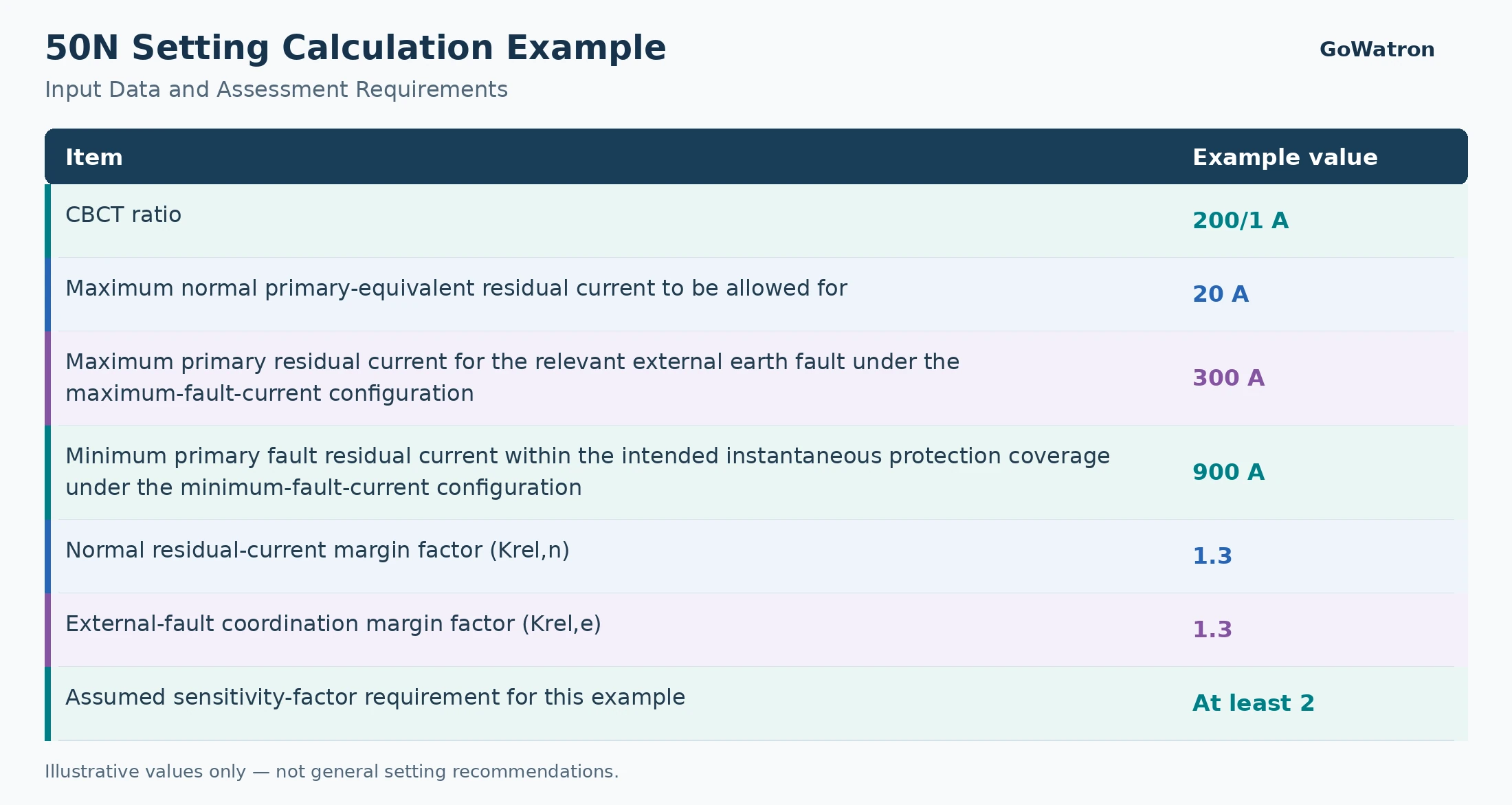
These values and assessment requirements are used only to illustrate the calculation process. They are not general setting recommendations. The two margin factors are assigned the same value solely to simplify this example; in practice, they should be determined separately.
In practice, the required sensitivity factor depends on the protection stage, assessment location, fault conditions, system earthing arrangement and applicable protection requirements.
① Check the normal residual-current constraint:
\[ I_{\mathrm{set,pri}} \geq 1.3\times20 = 26\ \mathrm{A} \]
②etermine the instantaneous pickup requirement from the external earth fault:
\[ I_{\mathrm{set,50N,pri}} > 1.3\times300 = 390\ \mathrm{A} \]
Assuming that the relay setting range and resolution permit, select:
\[ I_{\mathrm{set,50N,pri}}=400\ \mathrm{A} \]
③ Convert to the secondary setting:
\[ n_{\mathrm{CT}}=\frac{200}{1}=200 \]
\[ I_{\mathrm{set,50N,sec}} = \frac{400}{200} = 2.00\ \mathrm{A} \]
Verify sensitivity within the intended instantaneous protection coverage:
\[ K_{\mathrm{sen}} = \frac{900}{400} = 2.25 \]
The calculated sensitivity satisfies the assumed requirement of \(K_{\mathrm{sen}}\geq2\). The selected pickup also exceeds both the normal residual-current constraint and the external-fault coordination threshold.
This result confirms only that the pickup and sensitivity checks are satisfied under the stated assumptions. Final verification must also address CT performance, transient errors, relay operating characteristics, actual protection coverage and coordination with 51N and other protection functions.
4. Directional Earth-Fault Overcurrent (67N) Settings
In addition to the current pickup and operating time, 67N settings must define:
- Forward and reverse directions;
- The polarising quantity and its minimum threshold;
- The relay characteristic angle or applicable directional criterion;
- The operating sector or active/reactive component thresholds;
- The response to insufficient polarising quantities and VT circuit abnormalities.
These parameters must be selected according to the neutral earthing arrangement, network fault characteristics and relay algorithm. Different relays may use different voltage polarities and phase-angle conventions. A fixed characteristic angle or operating sector must therefore not be applied to every relay.
The 67N pickup must account for normal residual current, measurement errors, sensitivity to forward faults and coordination requirements. Reverse faults are normally restrained by the directional element. Setting the pickup above the maximum reverse-fault current is therefore not a general setting principle.
Verification should confirm reliable operation for forward faults, reliable restraint for reverse faults and the relay’s actual behaviour when the polarising quantity is insufficient.
5. Operating-Time Settings
Definite-time earth-fault protection is generally coordinated between upstream and downstream devices according to:
\[ t_{\mathrm{up}} \geq t_{\mathrm{down}}+\Delta t \]
- Here, \( t_{\mathrm{up}} \)and \\( t_{\mathrm{down}} \)are the upstream and downstream relay operating times, respectively; and \( \Delta t \) is the coordination time interval.
- The coordination interval must allow for the downstream circuit-breaker interruption time, relay timing tolerances, relevant reset or overshoot characteristics and a safety margin. It should be determined according to the applicable setting requirements. A range of 0.3–0.5 s may be used in some engineering schemes, but it is not a fixed value for every system.
- For inverse-time protection, upstream and downstream curves must be checked over the relevant fault-current range. Comparing operating times at only one current value is insufficient.
- The directional criterion in 67N can improve selectivity in complex networks, but it does not necessarily permit a shorter delay than 51N. Its operating time must still be determined by the specific coordination scheme.
6. Additional Considerations
Practical zero-sequence protection settings should also account for:
- High-resistance earth faults: Fault resistance may reduce residual current below the conventional pickup setting. More sensitive measurement, suitable earth-fault criteria or supplementary protection may be required. Adding residual-voltage information does not necessarily resolve every high-resistance fault-detection problem.
- Unearthed and resonant-earthed systems: Feeder phase-to-earth capacitance, Petersen-coil compensation, active residual current and intermittent earth-fault behaviour must be considered when selecting the faulted-feeder identification and protection method.
- CT selection and installation: Check the CT ratio, accuracy, saturation characteristics, polarity and CBCT conductor routing. Low-current applications also require assessment of the relay input sensitivity and measurement errors.
- Changes in operating configuration: Source switching, bus-section arrangements, parallel operation and distributed-generation connections can change fault-current magnitude and direction. Separately verified setting groups may be required.
- Intermittent faults and timer logic: Establish the protection reset time, timer-reset behaviour and whether cumulative timing is provided. External blocking or timer-reset signals are scheme-specific features and must be configured according to the relay manual and selectivity requirements.
- Auto-reclosing and interlocking: The relationship between earth-fault protection, auto-reclosing, switch-onto-fault acceleration and other blocking conditions must be verified for the actual protection scheme.
Summary: Zero-sequence overcurrent protection relays (ANSI 50N/51N/67N) detect earth faults using residual current and, where applicable, directional information. The 50N function provides rapid operation, 51N uses definite-time or inverse-time characteristics for coordination, and 67N adds a directional criterion to the overcurrent condition. Setting calculations must distinguish between \( I_0 \) and \( 3I_0 \), and between primary and secondary quantities. The system earthing arrangement, fault-current distribution, CT characteristics and protection coordination must all be considered to achieve an appropriate balance of security, selectivity, sensitivity and operating speed.


