Transformer Overcurrent Protection Relays: Operating Principle and ANSI 50/51 Setting Calculations
- Transformer overcurrent protection relays continuously monitor transformer currents through current transformers (CTs). When the measured current exceeds the configured pickup setting and the relevant operating conditions are satisfied, the relay sends a trip command to the circuit-breaker to clear the fault.
- For small and medium-sized distribution transformers, overcurrent protection may serve as the main protection. For larger power transformers, it is generally applied as backup to transformer differential protection (ANSI 87T).
1. Main Protection Functions
- (ANSI 50) Instantaneous Overcurrent Protection: Operates without intentional time delay and is mainly used to clear high-current faults rapidly.
- (ANSI 51) Time Overcurrent Protection: Operates with definite-time or inverse-time characteristics and provides selective coordination with upstream and downstream protection.
- (ANSI 50N/51N) Earth-Fault Overcurrent Protection: Detects earth faults affecting transformer windings and connected circuits.
- The ANSI 50 element must remain secure during transformer energisation and external through-faults. The ANSI 51 element must not pick up at the maximum load current but must retain sufficient sensitivity to the minimum fault current.
2. Operating Principle
Transformer overcurrent protection relays operate as follows:
- The CTs measure the three-phase currents of the transformer.
- The relay compares the measured currents with the configured pickup settings.
- When any phase current exceeds the pickup setting, ANSI 50 operates without intentional time delay, while ANSI 51 initiates timing.
- When all operating conditions are satisfied, the relay sends a trip command.
- The circuit-breaker clears the fault, and the relay stores protection events and disturbance records.
Directional overcurrent protection (ANSI 67) may be required in ring networks, multi-source systems, or systems containing distributed generation. Voltage-restrained or voltage-controlled overcurrent protection may be applied when conventional overcurrent elements cannot provide adequate sensitivity and selectivity.
3. ANSI 50/51 Setting Calculations
Consider a 10 MVA, 33/11 kV transformer with the following parameters:
| Parameter | Value |
| Rated Power | 10 MVA |
| Rated Voltage | 33/11 kV |
| Percentage Impedance | 8% |
| HV-Side CT Ratio | 200/1 A |
| Maximum Load Current | 1.2 times the rated current |
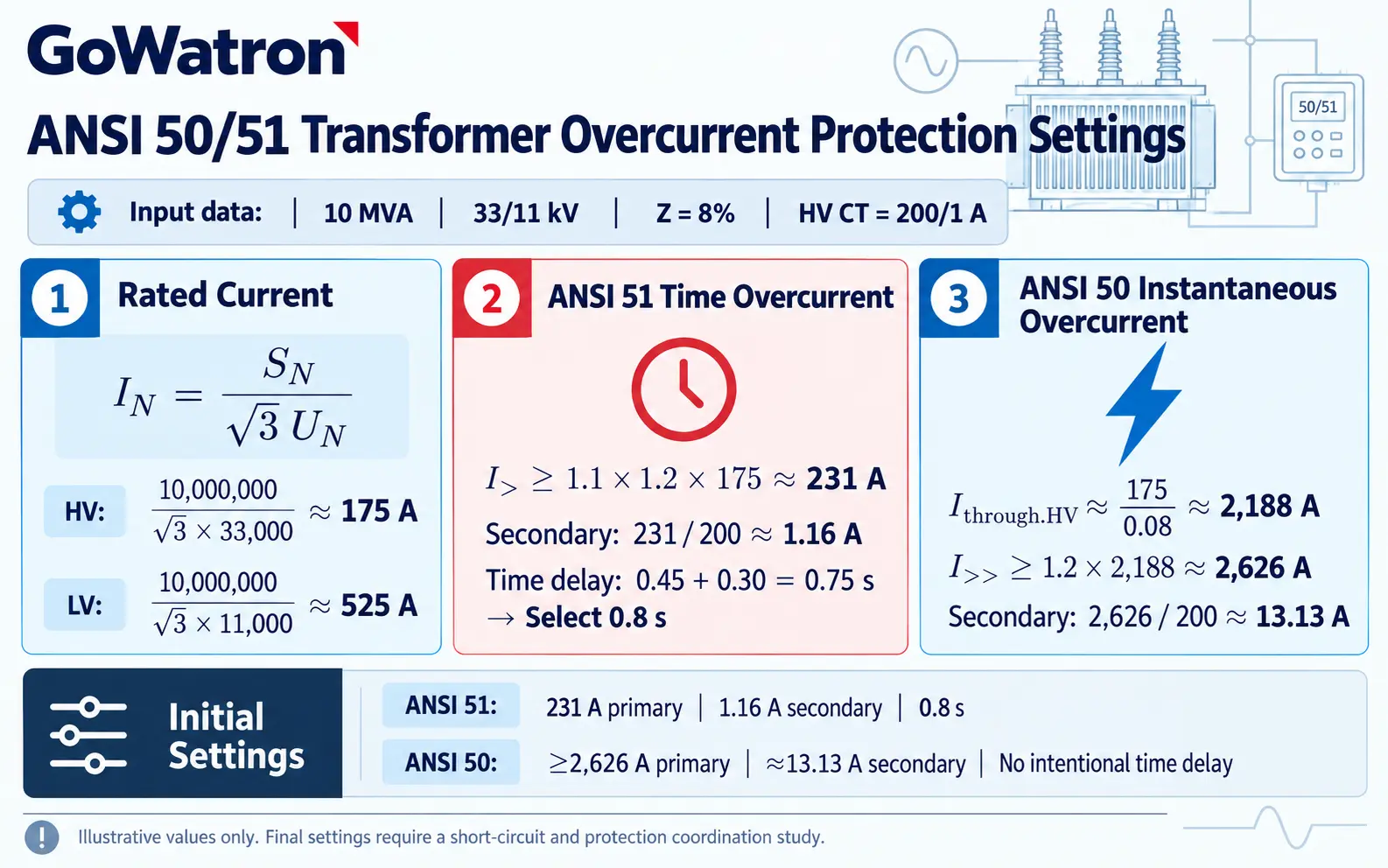
4. ANSI 50/51 Setting Summary
| Protection Function | Primary Pickup | Equivalent Secondary Pickup | Time Delay |
| ANSI 51 Time Overcurrent | 231 A | Approximately 1.16 A | 0.8 s |
| ANSI 50 Instantaneous Overcurrent | ≥2,626 A | Approximately 13.13 A | Without intentional time delay |
These values illustrate the setting procedure for transformer overcurrent protection relays. They must not be applied directly to an actual installation.
The final settings must also be checked against:
- Maximum load current and permissible transformer overload;
- Transformer magnetising inrush current;
- Maximum external through-fault current;
- Minimum internal and remote-end fault currents;
- CT ratio, accuracy class, and saturation characteristics;
- Upstream and downstream protection time delays.
If the ANSI 50 element cannot provide both sensitivity and selectivity, it should be disabled or set with an appropriate intentional time delay. Transformer differential protection should then provide rapid clearing of internal faults.
5. Transformer Overcurrent Protection Relay Selection
| Recommended Model | Application Range | Recommended Application |
| GWPR100-I Digital Integrated Protection Relay | Systems rated up to 13.8 kV | Ring main units, compact substations, and small and medium-sized distribution transformers |
| GWPR200-T Transformer Protection Relay | Systems rated up to 33 kV | Distribution, station-service, auxiliary, and renewable-energy step-up transformers |
| GWPR300-TB Transformer Backup Protection Relay | 33–132 kV systems | Backup protection of power transformers on the HV or LV side |
GWPR100-I
- The GWPR100-I is suitable for compact distribution applications in systems rated up to 13.8 kV. It combines protection, measurement, control, and communication functions and can be installed in ring main units, compact substations, and medium-voltage switchgear.
GWPR200-T
- The GWPR200-T is designed for transformer protection in systems rated up to 33 kV. It supports ANSI 50/51, ANSI 50N/51N, voltage protection, frequency protection, and transformer non-electrical protection.
- It also integrates measurement, circuit-breaker control, event recording, disturbance recording, and communication functions.
GWPR300-TB
- The GWPR300-TB is designed for backup protection of power transformers in 33–132 kV systems. It can provide directional overcurrent protection, overcurrent protection with composite voltage blocking, earth-fault overcurrent protection, overload protection, event recording, disturbance recording, and substation automation communication.
6. Relationship Between Overcurrent Protection and Differential Protection
- Transformer overcurrent protection relays operate mainly based on fault-current magnitude and the configured time delay. They are widely used for transformer overcurrent protection and system backup protection.
- For large or important transformers, overcurrent protection may not detect certain inter-turn faults or low-level internal faults with sufficient sensitivity.
- The GWPR300-TD Transformer Differential Protection Relay can therefore be applied as the main protection for internal faults in two-winding or three-winding power transformers with voltage ratings up to 132 kV.
A typical protection arrangement is as follows:
- The GWPR300-TD provides transformer differential main protection.
The GWPR300-TB provides overcurrent, earth-fault, and system backup protection.
7. Quick Selection Guide
- For distribution transformers, ring main units, or compact substations in systems rated up to 13.8 kV, select the GWPR100-I.
- For distribution, station-service, or auxiliary transformers in systems rated up to 33 kV, select the GWPR200-T.
- For backup protection of power transformers in 33–132 kV systems, select the GWPR300-TB.
- For large or important transformers, the GWPR300-TD differential relay may be combined with the GWPR300-TB backup relay to provide high-speed main protection and coordinated backup protection.
8. Information Required for Selection and Quotation
To select and configure transformer overcurrent protection relays accurately, provide the following information:
- Transformer rated power and rated voltages;
- Percentage impedance and vector group;
- Neutral earthing method;
- CT and VT ratios;
- Required ANSI protection functions;
- Communication protocols and IEC 61850 requirements;
- Local switchgear mounting or centralised panel mounting.
Conclusion
- The essential requirement when setting transformer overcurrent protection relays is to achieve the correct balance among sensitivity, selectivity, and operating speed.
- ANSI 51 must not pick up at the maximum load current and must coordinate with downstream protection. ANSI 50 must remain secure during transformer energisation and external through-faults while retaining adequate sensitivity to internal faults.
- The GWPR100-I is suitable for distribution applications in systems rated up to 13.8 kV, the GWPR200-T for transformer protection in systems rated up to 33 kV, and the GWPR300-TB for backup protection of power transformers in 33–132 kV systems. For large or important transformers, the GWPR300-TD may be added as transformer differential main protection.
- Final protection settings must always be based on the actual transformer data, short-circuit study, and protection coordination study.


