Transformer Protection Systems: Protection Functions, Typical Configurations and Relay Selection
- Transformers are critical assets in power plants, substations, renewable-energy installations and industrial power-distribution systems. Winding short circuits, earth faults, overexcitation, overloading, mechanical faults and abnormal non-electrical conditions can damage the transformer, interrupt the power supply and, in severe cases, cause a fire.
- A transformer protection system monitors electrical quantities and non-electrical conditions, including current, voltage, frequency, gas accumulation, pressure, temperature and oil level. It identifies internal faults, external faults and abnormal operating conditions, then initiates an alarm, issues a blocking signal or sends a trip command according to the severity of the condition.
Transformer Protection Systems – Selection Guide ; https://www.gowatron.com/products/transformer-protection-relays/
1. Components of a Transformer Protection System
A complete transformer protection system normally comprises:
- transformer differential main protection;
- HV-, MV- or LV-side backup protection;
- restricted earth-fault protection;
- transformer non-electrical protection;
- current transformers (CTs), voltage transformers (VTs) and secondary circuits;
- circuit-breaker tripping and trip-circuit supervision;
- sequence-of-events (SOE) recording and fault recording;
- communication and time-synchronisation facilities; and
- a DC control power supply.
Modern numerical protection relays can integrate protection, measurement, control, communication and fault-recording functions. Electrical protection cannot, however, completely replace transformer-mounted non-electrical protection devices and their associated protection functions.
In this article, transformer non-electrical protection refers to protection and supervision functions based on transformer-mounted gas, pressure, temperature, oil-level and cooling-system signals. Electrical and non-electrical protection functions must be properly coordinated.
2. Common Transformer Faults and Abnormal Conditions
2.1 Internal Faults
Typical internal faults include:
- phase-to-phase winding short circuits;
- interturn short circuits;
- winding earth faults;
- bushing and connection faults;
- on-load tap-changer faults;
- multiple earth faults on the core or core clamp; and
- insulation deterioration or breakdown.
Internal electrical faults are normally cleared rapidly by differential protection. Gas generation, rapid pressure rise and abnormal temperature conditions are primarily detected by transformer-mounted non-electrical protection.
2.2 External Faults
- A short circuit on a line or busbar can cause a high through-fault current to flow through the transformer. Although the fault lies outside the protected zone, sustained high current can cause mechanical deformation and thermal damage to the windings.
- Phase overcurrent and earth-fault protection are therefore normally provided on the relevant sides of the transformer as backup for the transformer main protection and the protection of adjacent equipment.
2.3 Abnormal Operating Conditions
Typical abnormal operating conditions include:
- prolonged overloading;
- overexcitation;
- system overvoltage or low frequency;
- excessive oil or winding temperature;
- abnormal oil level;
- cooler, fan or oil-pump failure;
- current unbalance; and
- circuit-breaker failure.
Depending on the severity of the condition, the protection system may initiate alarms in stages, start cooling equipment, block on-load tap-changer operation or issue a delayed or instantaneous trip command.
3. Principal Transformer Protection Functions
3.1 (ANSI 87T) Transformer Differential Protection
Transformer differential protection compares the currents on the different sides of the transformer. After ratio and phase-displacement compensation, the currents should be substantially balanced under normal operating conditions and during external faults. A fault within the differential protection zone produces a significant differential current.
The differential current is defined as:
\[ I_\text{diff} = \left| \sum_{k=1}^{n} \vec{I}’_k \right| \]
where:
- \( I_{\mathrm{diff}} \)is the differential current;
- \( \vec{I}’_k \) is the current on transformer side k, referred to a common base and compensated for phase displacement; and
- \( n \) is the number of transformer sides included in the differential protection zone.
The operating characteristic depends on the protection relay algorithm and may use one or more bias slopes and breakpoints. A simplified single-slope characteristic with a minimum pickup threshold can be expressed as:
\[ I_{\mathrm{diff}} > \max\left(I_{\mathrm{pickup}},\, S I_{\mathrm{bias}}\right) \]
where:
- \( I_{\mathrm{pickup}} \) is the minimum differential pickup current;
- \( I_{\mathrm{bias}} \)is the bias or restraint current; and
- \( S \)is the percentage-bias slope.
This is a simplified representation. Actual settings must follow the relay manufacturer’s published operating characteristic, including any additional bias slopes, breakpoints, high-set differential elements and CT-saturation logic.
Modern transformer differential protection typically provides:
- ratio and vector-group compensation;
- biased differential protection;
- zero-sequence current elimination;
- magnetising-inrush detection;
- CT-saturation detection;
- high-set differential protection;
- CT-circuit supervision;
- SOE recording; and
- fault recording.
Transformer energisation can produce large magnetising-inrush currents. Protection relays normally use harmonic restraint, harmonic blocking or waveform-based inrush detection to prevent unwanted differential operation.
3.2 (ANSI 64REF) Restricted Earth-Fault Protection
- Restricted earth-fault (REF) protection is primarily used to detect earth faults within the protected zone of a star-connected transformer winding.
- REF protection compares the residual current derived from the phase CTs with the current measured by the neutral CT. It provides a clearly defined protection zone, high operating speed and high sensitivity to earth faults. It is primarily applied to star-connected windings with a solidly earthed neutral or a neutral earthed through a low impedance.
- The function is commonly designated 64REF, although 87N or another manufacturer-specific designation may also be used. The applicable designation must be verified against the selected protection relay documentation.
3.3 (ANSI 50/51) Phase Overcurrent Protection
Phase overcurrent protection detects external phase faults and can also provide backup for transformer differential protection.
Protection settings should take into account:
- transformer rated current and maximum load current;
- permissible overload capability;
- magnetising-inrush current;
- maximum and minimum short-circuit currents;
- CT ratio and saturation performance;
- operating times of downstream protection; and
- transformer thermal withstand capability.
HV-side backup protection must be coordinated with LV-side busbar and feeder protection to prevent unnecessary transformer tripping for faults downstream of the transformer.
3.4 (ANSI 50N/51N and 50G/51G) Earth-Fault Overcurrent Protection
Earth-fault overcurrent protection detects earth faults using a neutral CT, residual current measurement or zero-sequence current calculated by the protection relay.
Its sensitivity and operating range depend on:
- transformer vector group;
- neutral earthing arrangement;
- neutral-earthing resistor parameters;
- CT locations; and
- system zero-sequence network.
Earth-fault protection must therefore be selected and configured according to the winding arrangement and system earthing method.
The suffixes N and G are applied differently by protection relay manufacturers. Depending on the relay design, 50N/51N may refer to neutral or residual overcurrent protection. 50G/51G may refer to earth-fault overcurrent protection based on the relay’s designated ground-current input or residual current measurement. Their precise definitions must be verified against the selected relay documentation and the project protection philosophy.
3.5 (ANSI 24) Overexcitation Protection
An increase in voltage or a reduction in frequency increases the core flux density of the transformer. This can cause core saturation, increased magnetising current and localised overheating.
Overexcitation is generally assessed using the voltage-to-frequency ratio. In per-unit terms, it may be expressed as:
\[ \left(\frac{V}{f}\right)_{\mathrm{pu}} = \frac{V/V_\mathrm{N}}{f/f_\mathrm{N}} \]
where:
- \( V \)is the measured voltage;
- \( V_{\mathrm{N}} \) is the rated voltage;
- \( f \)is the measured frequency; and
- \( f_{\mathrm{N}} \)is the rated frequency.
When the voltage-to-frequency ratio exceeds the limit defined by the transformer manufacturer’s overexcitation withstand curve, the protection relay may initiate alarms or trips in stages.
Overexcitation protection cannot be replaced by overvoltage protection alone. Even when the voltage remains within its normal range, a reduction in frequency may cause the \( V/f \) ratio to exceed the permissible limi
3.6 (ANSI 49) Thermal Overload Protection
Thermal overload protection uses load current and a thermal model to estimate the transformer’s thermal state. The calculation may also incorporate oil temperature, winding temperature, ambient temperature and cooling-system status.
Typical outputs and actions include:
- overload alarm;
- fan or oil-pump start command;
- transfer to a standby cooler;
- high-temperature alarm; and
- very-high-temperature trip.
The thermal-model parameters must be matched to the transformer cooling method, thermal time constants and permissible loading capability.
3.7 (ANSI 63, 26 and 71) Transformer Non-Electrical Protection
Transformer non-electrical protection uses sensors and mechanical relays mounted on the transformer and its ancillary equipment to detect abnormal conditions.
Typical functions include:
- Buchholz alarm for gas accumulation;
- Buchholz trip for rapid oil movement;
- on-load tap-changer gas protection;
- sudden-pressure protection;
- pressure-relief device operation;
- oil-temperature and winding-temperature supervision;
- oil-level supervision; and
- cooler, fan and oil-pump failure supervision.
Common ANSI device numbers include:
- (ANSI 63) pressure, gas or mechanical protection;
- (ANSI 26) apparatus thermal protection or supervision; and
- (ANSI 71) liquid-level supervision.
Cooler, fan and oil-pump failure signals do not have a universally applicable ANSI device number.
Gas accumulation, moderately high temperature and abnormal oil level normally initiate alarms. An oil surge detected by the Buchholz relay, a sudden pressure rise and very-high-temperature conditions may initiate tripping, subject to the transformer manufacturer’s requirements and the project protection philosophy.
The final alarm and trip logic must follow the transformer manufacturer’s requirements and the project design.
3.8 Other Supplementary Functions
Depending on the project requirements, the following functions may also be provided:
- (ANSI 59) overvoltage protection;
- (ANSI 27) undervoltage protection;
- (ANSI 59N) residual overvoltage protection;
- (ANSI 46) negative-sequence overcurrent protection;
- (ANSI 50BF) circuit-breaker failure initiating overcurrent element, used with the applicable breaker-failure timer and logic;
- (ANSI 60/60V) VT-circuit supervision, depending on the protection relay designation; and
- (ANSI 74/74TC) trip-circuit supervision, depending on the protection relay designation.
The precise ANSI suffixes and device designations used for VT-circuit supervision, trip-circuit supervision and circuit-breaker failure protection vary among manufacturers. They must be verified against the selected protection relay documentation and the project specification.
4. Typical Configurations and Recommended GoWatron Models
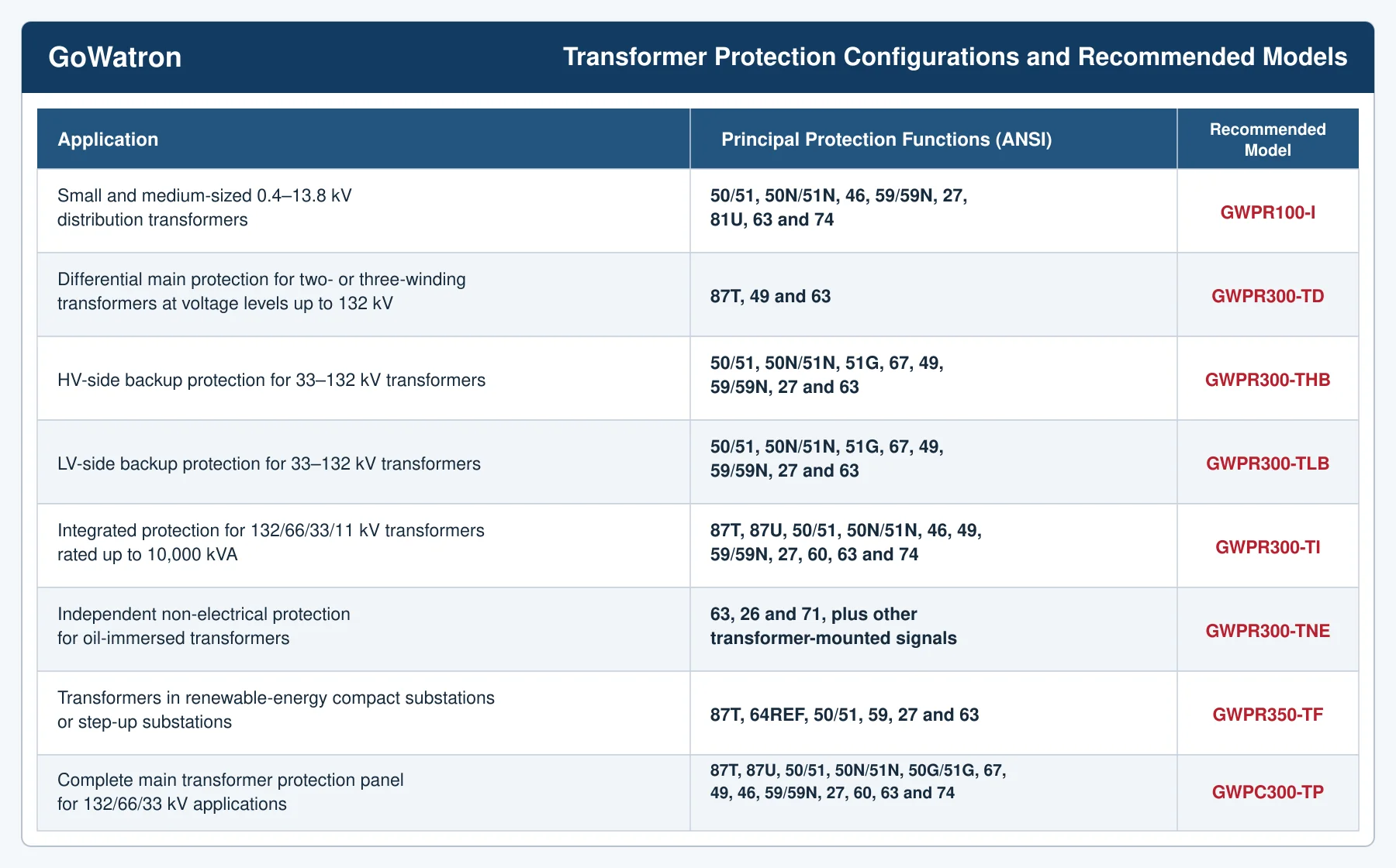
The ANSI device numbers indicate typical functions available with each model. The final protection functions must be verified against the selected protection relay, hardware version and project technical specification.
4.1 Medium- and Low-Voltage Distribution Transformers
- For 0.4–13.8 kV distribution transformers, compact substations and ring main units, the recommended model is:
GWPR100-I Digital Integrated Protection Relay
- The relay integrates overcurrent, earth-fault, voltage and negative-sequence protection with measurement, control, non-electrical signal inputs and event recording. It is suitable for small and medium-sized distribution transformers that do not require independent differential protection.
4.2 Important Power Transformers
- For important two- or three-winding power transformers in 33, 66 or 132 kV systems, the recommended segregated protection configuration is:
GWPR300-TD + GWPR300-THB + GWPR300-TLB + GWPR300-TNE
The principal responsibilities of the protection relays are:
- GWPR300-TD: transformer differential main protection;
- GWPR300-THB: HV-side backup protection;
- GWPR300-TLB: LV-side backup protection; and
- GWPR300-TNE: transformer non-electrical protection.
For a three-winding transformer, an additional MV-side backup protection relay may be required, depending on the protection zones and project requirements.
This arrangement provides hardware and functional separation between the main, backup and non-electrical protection relays. It is therefore suitable for projects with higher dependability, security and maintainability requirements.
4.3 Integrated Transformer Protection
- For transformers in 132, 66, 33 or 11 kV systems with rated powers up to 10,000 kVA, where reducing the number of protection relays and the required panel space is a priority, the recommended configuration is:
GWPR300-TI + GWPR300-TNE
In this configuration:
- GWPR300-TI integrates differential main protection, backup protection, measurement, fault recording and communication within one relay; and
- GWPR300-TNE provides independent transformer non-electrical protection.
The main and backup protection functions within the GWPR300-TI share the same relay hardware. Where the project specification requires main and backup protection to use independent hardware, a segregated protection configuration should be selected instead.
4.4 Transformer Differential Main Protection
The GWPR300-TD Transformer Differential Protection Relay is designed for two- and three-winding power transformers at voltage levels up to 132 kV.
Its principal functions include:
- (ANSI 87T) transformer differential protection;
- magnetising-inrush detection;
- ratio and vector-group compensation;
- multi-side current measurement;
- CT-circuit supervision;
- SOE and fault recording; and
- communication and time synchronisation.
The GWPR300-TD is normally applied with the GWPR300-THB, GWPR300-TLB and GWPR300-TNE protection relays.
4.5 Transformer Backup Protection
The following models are available for backup protection on 33–132 kV transformers:
- GWPR300-THB: HV-side backup protection relay; and
- GWPR300-TLB: LV-side backup protection relay.
The principal protection functions include:
- (ANSI 50/51) phase overcurrent protection;
- (ANSI 50N/51N) neutral or residual earth-fault overcurrent protection;
- (ANSI 51G) earth-fault overcurrent protection;
- (ANSI 67) directional overcurrent protection;
- (ANSI 49) thermal overload protection;
- (ANSI 59/59N) overvoltage and residual overvoltage protection; and
- (ANSI 27) undervoltage protection.
The exact meanings of the N and G suffixes depend on the selected protection relay configuration and must be confirmed from the applicable product documentation.
The backup protection must be coordinated with downstream busbar and feeder protection and with the upstream protection system in terms of operating time and sensitivity.
4.6 Transformer Non-Electrical Protection
The GWPR300-TNE Transformer Non-Electrical Protection Relay independently processes transformer-mounted non-electrical signals, including:
- Buchholz alarm and trip signals;
- on-load tap-changer gas-protection signals;
- sudden-pressure and pressure-relief signals;
- oil-temperature and winding-temperature signals;
- abnormal oil-level signals; and
- cooler, fan or oil-pump failure signals.
Each input may be configured to initiate an alarm or issue a delayed or instantaneous trip command, subject to the project requirements.
The GWPR300-TNE does not replace a differential or backup protection relay. It operates alongside electrical protection relays as part of a complete transformer protection system.
4.7 Renewable-Energy Compact Substations
- For compact substations in photovoltaic power plants, wind farms and renewable-energy step-up substations, the recommended model is:
GWPR350-TF Transformer Protection and Control IED
- This model integrates transformer protection, measurement, control, remote supervision and communication management. It is intended for projects requiring protection, bay control and communication functions within a single intelligent electronic device (IED).
4.8 Complete Transformer Protection Panel
- For projects requiring a complete control-room protection panel rather than individual protection relays, the recommended solution is:
GWPC300-TP Transformer Protection Panel
Depending on the project requirements, the panel may include:
- a GWPR300-TD differential protection relay;
- a GWPR300-THB HV-side backup protection relay;
- a GWPR300-TLB LV-side backup protection relay;
- a GWPR300-TNE non-electrical protection relay;
- circuit-breaker tripping and trip-circuit supervision;
- auxiliary relays, miniature circuit-breakers and terminal blocks; and
- fault-recording, communication and time-synchronisation equipment.
The GWPC300-TP is suitable for step-up and step-down transformers in 132/66/33 kV substations, power plants and industrial captive power systems.
5. Information Required for Protection Setting Calculations
Transformer protection setting calculations normally require:
- rated power and rated voltage of each winding;
- rated current and permissible overload capability;
- number of windings and vector group;
- transformer short-circuit impedance;
- neutral earthing arrangement;
- CT ratios, accuracy classes and saturation performance;
- maximum and minimum short-circuit currents;
- magnetising-inrush characteristics;
- overexcitation withstand curve;
- circuit-breaker operating times;
- upstream and downstream protection settings; and
- parallel and independent operation of transformers.
The protection settings should satisfy four fundamental requirements:
- Selectivity: isolate only the faulty equipment or the smallest practicable faulted section.
- Speed: clear severe internal faults rapidly.
- Sensitivity: reliably detect the minimum fault within the protected zone.
- Dependability and security: operate for faults within the protected zone while remaining stable during external faults and normal operating conditions
6. Communication and Automation Functions
Depending on the model and project configuration, GoWatron transformer protection relays can be integrated into a supervisory control and data acquisition (SCADA) or substation automation system to provide:
- current, voltage, power and frequency measurements;
- circuit-breaker and transformer-mounted signal supervision;
- transmission of protection operations and alarms;
- SOE recording;
- fault records in COMTRADE format;
- setting-group management;
- authorised remote reset and control;
- protection relay self-supervision; and
- communication-status supervision.
Common communication protocols include:
- IEC 61850;
- IEC 60870-5-103;
- IEC 60870-5-104;
- Modbus RTU; and
- Modbus TCP.
Common time-synchronisation methods include SNTP, IRIG-B and protocol-based time synchronisation. The available interfaces, protocols and time-synchronisation methods depend on the selected product configuration.
7. How to Select a Transformer Protection Relay
The following factors should be confirmed during relay selection:
- transformer rated power and voltage class;
- two-winding, three-winding or autotransformer construction;
- vector group and neutral earthing arrangement;
- CT and VT configuration;
- required differential, REF, overcurrent and earth-fault protection functions;
- number of non-electrical inputs and trip outputs;
- whether the main and backup protection functions require independent hardware;
- number of circuit-breakers and tripping scheme;
- communication protocols and network interfaces; and
- whether individual protection relays or a complete protection panel are required.
Transformer protection relays should not be selected solely by comparing the number of functions or price. Protection algorithms, hardware dependability, input and output capacity, communication compatibility, engineering support, commissioning services and after-sales technical support should also be evaluated.
8. Conclusion
- A complete transformer protection system should cover internal short circuits, winding earth faults, backup protection for external faults, overexcitation, overloading, transformer mechanical faults and abnormal non-electrical conditions.
For important power transformers in 33, 66 or 132 kV systems, the recommended configuration is:
GWPR300-TD + GWPR300-THB + GWPR300-TLB + GWPR300-TNE
In this configuration:
- GWPR300-TD provides transformer differential main protection;
- GWPR300-THB provides HV-side backup protection;
- GWPR300-TLB provides LV-side backup protection; and
- GWPR300-TNE provides gas, pressure, temperature, oil-level and cooling-system protection.
The final protection scheme and settings must be based on the transformer data, short-circuit calculations, neutral earthing arrangement, CT performance, circuit-breaker configuration and a project-specific protection-coordination study.


