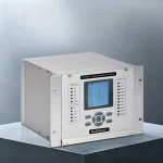
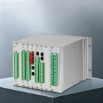
GWPR350-TF Transformer Protection and Control IED
Product Desc
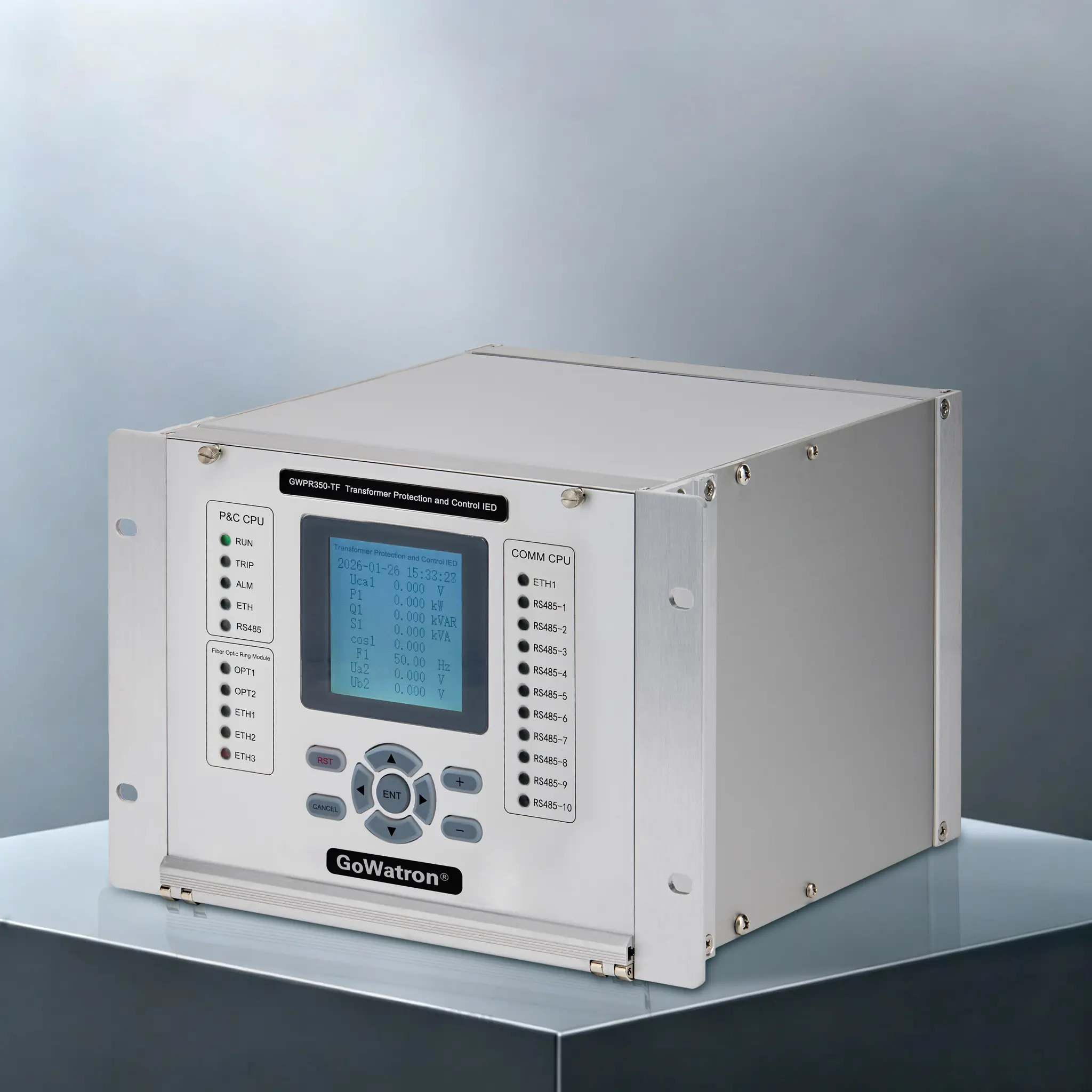
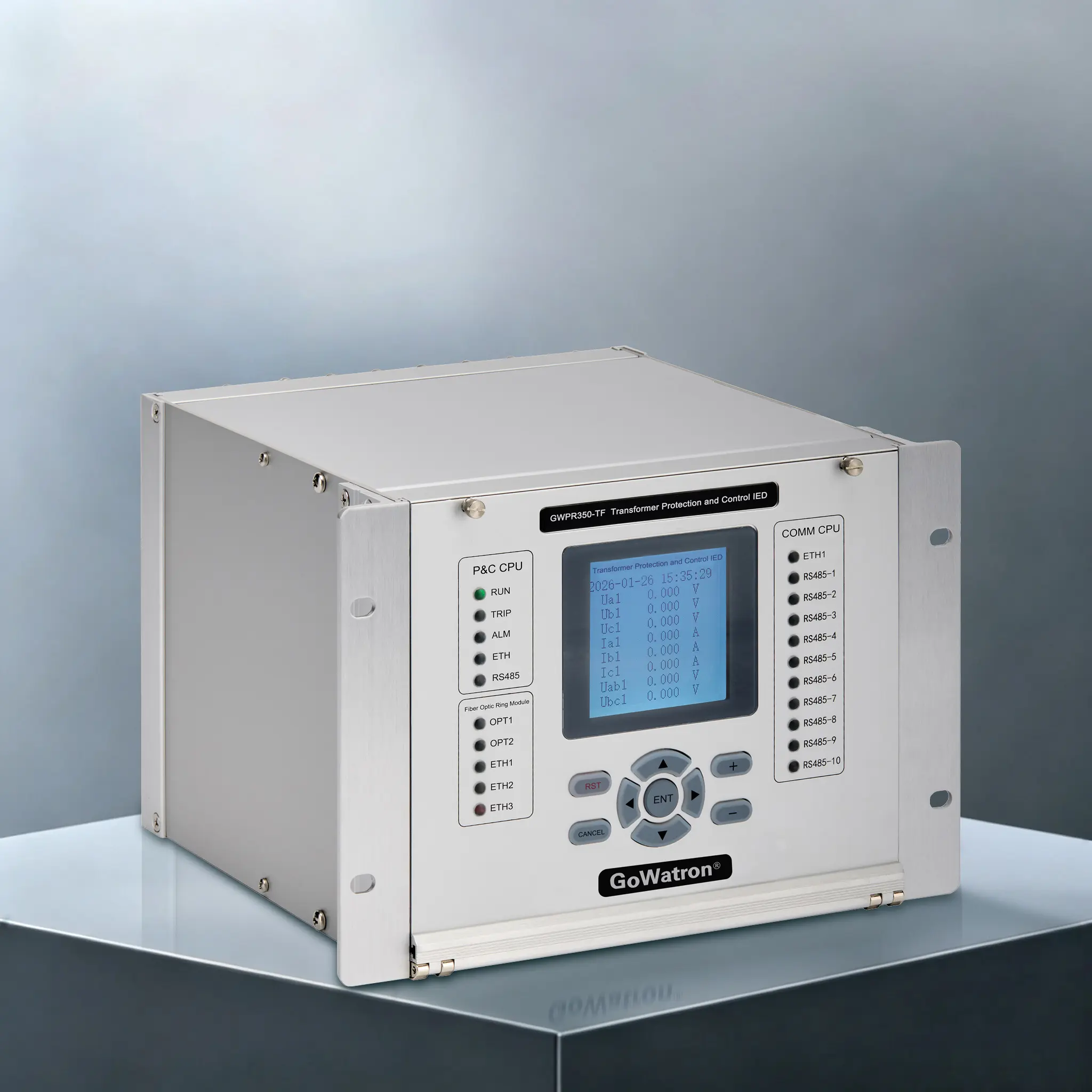
The GWPR350-TF is a multifunctional IED that combines transformer protection, measurement & control, and protocol gateway capabilities. It provides dedicated trip protection for the box-type substation, aggregates data from combiner boxes, inverters, and video surveillance systems, and forwards it to the SCADA system. With support for both on-site control and remote supervision, it ensures maximum security and stability for renewable energy.
- Features 2 self-healing optical-fiber interfaces and 3 self-healing electrical ports for optical-fiber ring-network formation.
- 2 CPU-integrated Ethernet communication interfaces.
- 2 CPU-integrated RS485 communication ports.
- Supports communication protocols including Modbus, IEC 60870-5-103, IEC 60870-5-104, with IEC 61850 as an optional protocol.
- Protocol conversion: Fitted as standard with 10 RS485 interfaces and 2 Ethernet communication interfaces to function as a communication manager.




Accuracy
≤ 0.2%

Quick Response
≤ 100ms

Reliable Protection
Comprehensive Protection

Quality Assurance
ISO 9001 Certified

Technical Support
24/7 Expert Support

Fast Delivery
Global Shipping

Warranty
2-Year Warranty
Scope of Application
- The GWPR350-TF is a transformer protection and control IED specifically designed for pad-mounted (box-type) transformers used in renewable energy plants, including photovoltaic (PV) and wind power stations. The device provides comprehensive protection as well as four-remote functions: remote indication, remote metering, remote control and remote setting for wind turbine step-up transformers, as well as for combiner boxes, DC cabinets, and inverters within PV arrays.
- Via a self-healing fiber-optic ring network, the IED can be integrated into the substation’s integrated monitoring and control system, enabling remote management of PV generation units and wind farms from the central substation. This fully meets the operational requirements for digitalized, intelligent, and unmanned/less-manned management of solar and wind power installations.
Protective Functions (with ANSI Device Numbers)
(ANSI 87T) Transformer Differential Protection:
- Includes instantaneous differential high-set trip, percentage-restraint differential protection with second-harmonic restraint, differential-current threshold alarm, and CT secondary open-circuit detection.
(ANSI 50/51) Two Sets of Three-Stage Overcurrent Protection:
- Each stage is equipped with an independent software enable/disable switch (configuration bit), along with individual pickup current and operating time delay settings. All stages operate independently.
(ANSI 50N/51N) Zero-Sequence Overcurrent Protection:
- Triggers a time-delayed trip or alarm when the zero-sequence current exceeds the set threshold.
(ANSI 63/26/71) Non-Electrical Protection:
- Provides direct trip interfaces for the following signals: heavy Buchholz relay trip, light Buchholz relay alarm, over-temperature trip, high-temperature alarm, low oil level, SF₆ pressure abnormality, blown HV-side fuses(Phase A/B/C), enclosure-gate trip, smoke alarm, door-open alarm, and non-electrical inputs 1–4. Trip-or-alarm operating modes are selectable via control words, with remote status acquisition available simultaneously.
(ANSI 59) Overvoltage Protection:
- Enabled via dedicated protection links/switches and control words; initiates a time-delayed trip or alarm when the phase-to-phase voltage exceeds the set value.
(ANSI 27) Undervoltage Protection:
- Enabled via undervoltage protection links/switches and control words. It incorporates a minimum operating threshold—the undervoltage protection is blocked when all three phase-to-phase voltages fall below 57 V. A time-delayed trip or alarm is issued upon condition satisfaction.
(ANSI 60FL) PT (Voltage Transformer) Disconnection / Fuse Failure Detection:
- Generates a 10-second delayed alarm upon detecting any of the following conditions: phase-to-phase voltage difference exceeding 18 V between any two phases, negative-sequence voltage exceeding threshold, and positive-sequence current present.
Control and Measurement (C&M) Functions
Telemetry (Measurement)
- AC Measurements: Three-phase currents, three-phase voltages, frequency, power factor, active power, reactive power, active energy, and reactive energy.
- Measurement Channels: 6 analog current inputs, 6 analog voltage inputs.
- DC Measurements: 6 channels in total. Standard configuration: 3 × 4–20 mA analog inputs + 3 × Pt100 RTD inputs. Optional variant: all 6 channels configured for 4–20 mA.
Remote Signaling (Indication)
- 42 user-configurable binary inputs (DI); 14 of them are factory-preset for non-electrical-protection signals.
Remote Control
- 9 relay outputs (DO) configurable for protection tripping or general remote control purposes.
Breaker Trip-Close Circuit
- Optional 1- or 2-channel breaker control circuits, auto-adaptive for trip-close current 0.5 A to 5 A, supporting both AC and DC actuation. Required ordering option.
Communication Interfaces
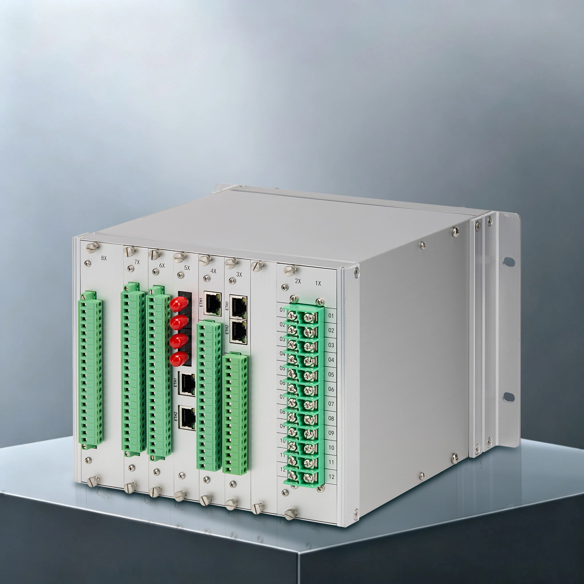
- 2 self-healing optical-fiber ports and 3 self-healing RJ45 Ethernet ports for ring-network application
- 2 built-in CPU Ethernet ports
- 2 built-in RS485 serial ports
- Supported protocols: Modbus, IEC 60870-5-103, IEC 60870-5-104; IEC 61850 is optional.
Protocol Conversion
- Optional protocol-conversion module provides 10 RS485 serial ports and 2 Ethernet ports for gateway / communication-management-unit functions.
Event & Waveform Recording
- Stores up to the latest 1,024 SOE (Sequence-of-Events) records, 1,024 operation logs, and 16 fault-recorder files. Fault-recording follows standard COMTRADE format, supporting up to 13 analog channels at 1 ms sampling interval.
Device Features
- Housed in a standard 4U half-width aluminum-alloy chassis, with high vibration-withstand and heavy-interference resistance. Designed for harsh environments; operating temperature range: −40 °C to +70 °C.
- Built around a 32-bit ARM processor, high-precision 16-bit ADC and large-capacity non-volatile memory, with industrial-grade Ethernet circuitry. Key components adopt industrial-grade imported devices to guarantee high stability and reliability.
- Analog-input sampling rate: 64 samples per power-frequency cycle. Digital filtering and optimized FFT algorithms deliver high-accuracy real-time data; current-voltage measurement accuracy class 0.5, with strong anti-noise performance during data acquisition.
- Wide-temperature LCD display, functional within −40 °C to +80 °C.
- 42 configurable high-voltage-tolerant binary inputs (including non-electrical-protection inputs).
- 9 configurable matrix-form relay outputs.
- Optional 6-channel DC measurement: 3 × Pt100 RTD inputs and 3 × 4–20 mA analog inputs for transformer temperature and site-environment monitoring.
- Wide-range auxiliary power supply (AC/DC 176–600 V), designed to cope with voltage swell and surge events frequently seen in PV and wind-power sites.
- High-reliability multi-Ethernet redundancy; 10/100 M auto-negotiation. An extensive built-in protocol library ensures interoperability with third-party equipment and systems. Compliant with Modbus-TCP, IEC 60870-5-103, IEC 60870-5-104; IEC 61850 is optional.
- Supports IRIG-B time-synchronization and SNTP.
- Optional protocol-conversion module supports multi-device local access and protocol translation for optical-link uplink to plant-wide SCADA / monitoring system.
- Flexible multi-Ethernet cascading modes. Comprehensive on-line / off-line commissioning tools are provided, supporting reliable firmware upgrade, parameter download, data query and message monitoring. Built-in self-diagnostics and auto-recovery functions.
- Adopts multi-layer PCB and SMT automated manufacturing for good electrical performance.
- High-level electromagnetic-interference immunity, having passed 14 EMC test items at the highest severity levels.


