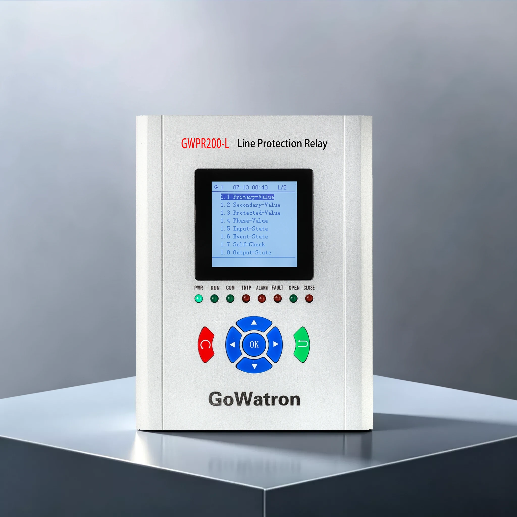
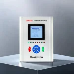
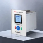
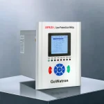
GWPR200-L Line (Feeder) Protection Relay
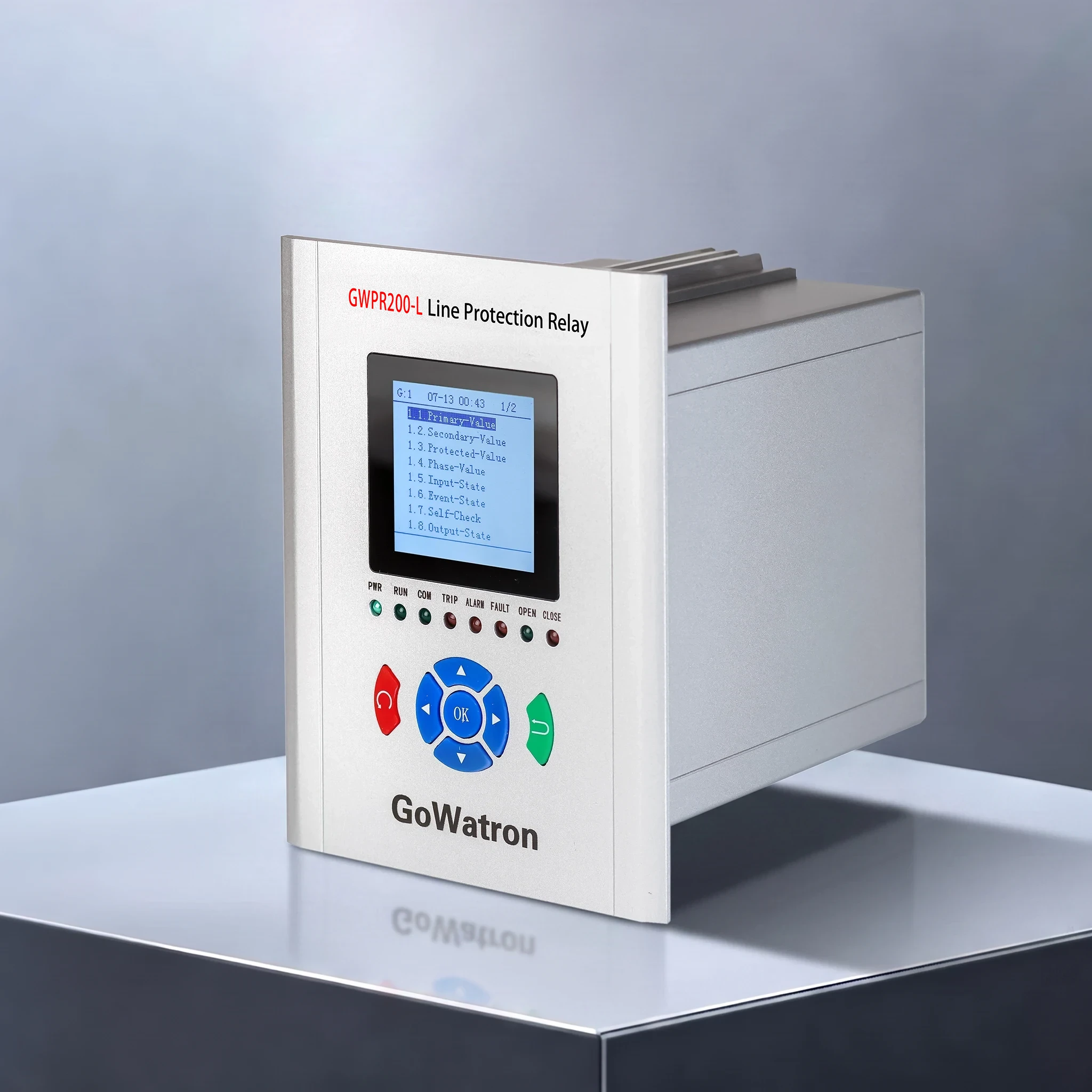
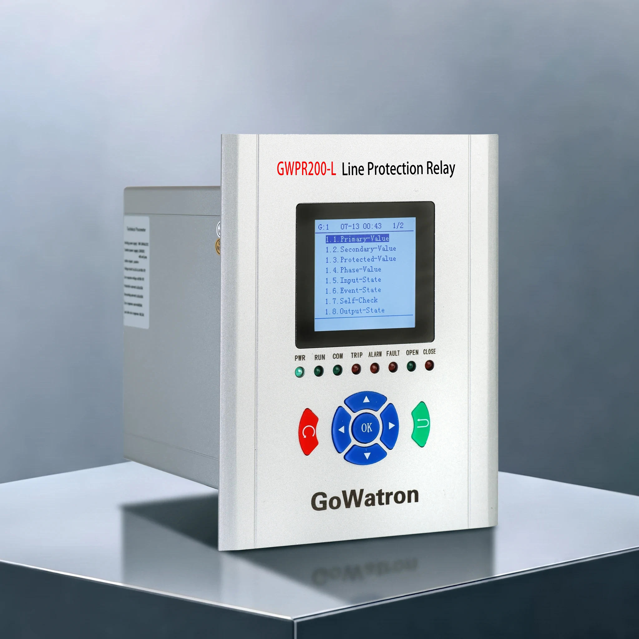
The GWPR200-L Feeder Protection Relay is specially designed for feeder switch cabinets and independently developed by GoWatron. It is applicable to distribution lines of 35kV and below with ungrounded, resistance-grounded and arc suppression coil neutral systems (consult the manufacturer for solidly grounded systems). Two installation modes are available: embedded local mounting inside switch cabinets and centralized panel mounting in control rooms. The device integrates line fault protection, high-precision electrical measurement and control, multi-channel remote signal acquisition, fault recording, SOE event logging and multi-protocol communication in one unit.
- Equipped with dual Ethernet + RS485 dual-channel communication hardware, it is compatible with conventional substation automation systems and digital distribution substations.
- Standard communication protocols: Modbus RTU, IEC 60870-5-103, supporting full uploading of measured values, remote status signals, protection operations, alarms, fault recording files and protection setting values;
- Optional extended function: Dual-port Ethernet IEC 103 communication, compatible with digital distribution reconstruction projects.




Product Functions
Full Set of Line Protection Functions
- (ANSI 50/67) Instantaneous Overcurrent Protection (Trip, with optional directional blocking and composite voltage blocking composed of negative-sequence voltage & low voltage)
- (ANSI 50/67) Short-delay Instantaneous Overcurrent Protection (Trip, with optional directional blocking and composite voltage blocking composed of negative-sequence voltage & low voltage)
- (ANSI 51/67) Definite Time Overcurrent Protection (Trip, with optional directional blocking and composite voltage blocking composed of negative-sequence voltage & low voltage)
- (ANSI 51) Inverse Time Overcurrent Protection (Trip, three standard IEC inverse time characteristic curves: Normal / Very / Extreme selectable, composite voltage blocking optional)
- (ANSI 50N) Residual Post-Acceleration Protection (Trip, enabled temporarily after reclosing to accelerate removal of recurring faults)
- (ANSI 49) Overload Protection (Alarm or trip selectable, calculated based on RMS current value)
- (ANSI 50N) Residual Instantaneous Overcurrent Stage I (Trip)
- (ANSI 51N) Residual Definite Time Overcurrent Stage II (Alarm or trip selectable)
- (ANSI 51N) Residual Inverse Time Overcurrent Protection (Trip, three standard IEC inverse time characteristic curves: Normal / Very / Extreme selectable)
- (ANSI 79/50N) Residual Reclosing Post-Acceleration Protection (Trip, dependent on reclosing function)
- (ANSI 79) Three-Phase Single-Shot Auto-Reclosing (No Check / Dead Line Check / Synchronism Check selectable, triggered by protection operation or position mismatch)
- (ANSI 81L) Underfrequency Load Shedding Protection (Trip)
- (ANSI 59) Overvoltage Protection (Trip)
- (ANSI 27) Undervoltage Protection (Alarm or trip selectable)
- (ANSI 59N) Residual Overvoltage Protection (Alarm or trip selectable)
- PT Broken Circuit Supervision (Alarm, detects single-phase, two-phase PT breakage and three-phase voltage loss)
- Control Circuit Broken Supervision (Alarm, monitors integrity of trip/closing coils and external DC power circuits)
All above protection functions are equipped with independent soft enable switches for flexible configuration according to feeder operation requirements.
Auxiliary Functions
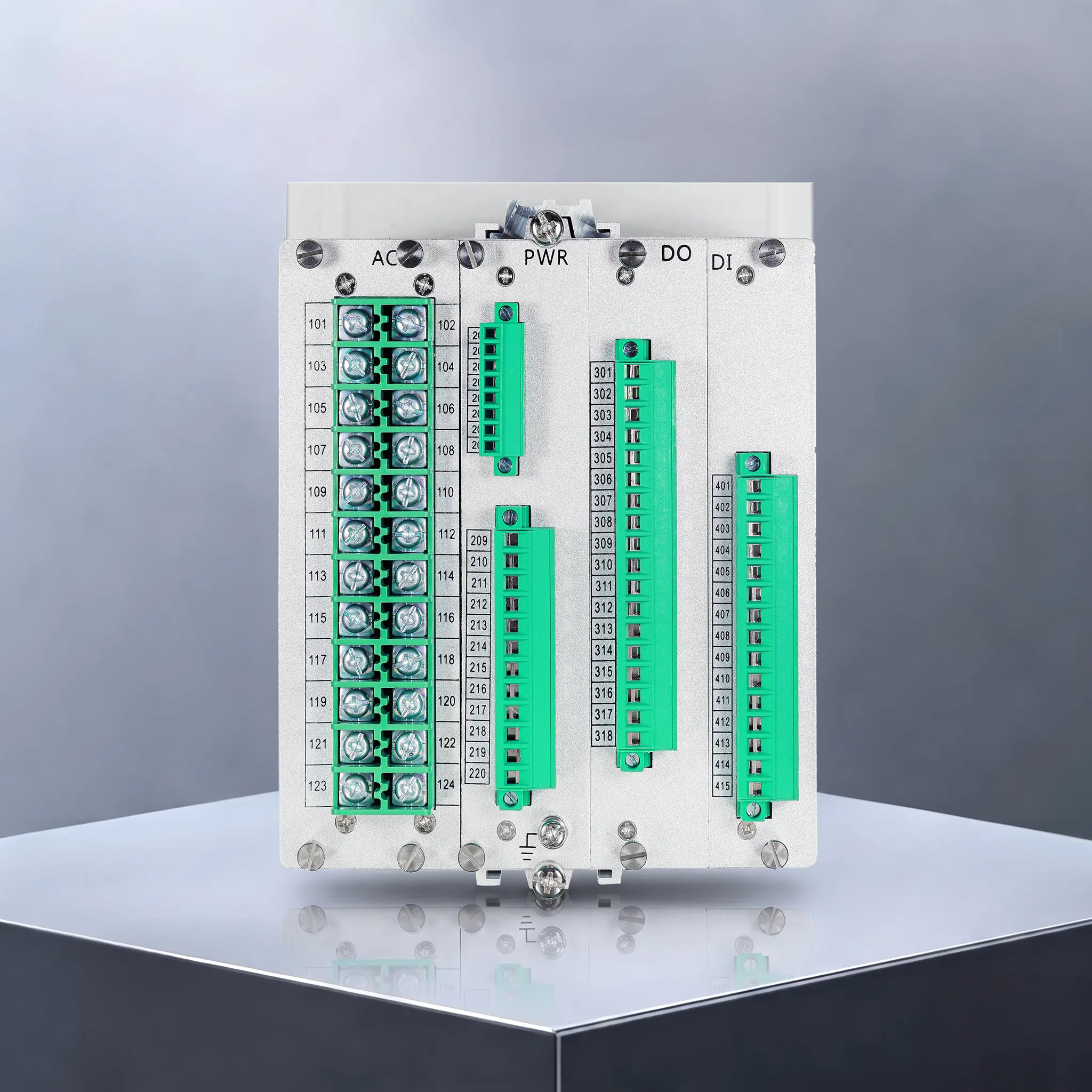
- Measurement & Acquisition: Real-time collection of three-phase voltages, residual voltage, three-phase currents, residual current, active/reactive power, frequency, bidirectional electric energy; Standard 14 remote digital inputs (2 configurable pulse counting channels), 8 independent passive trip/closing output relays.
- Event & Time Synchronization: Six categories of data stored separately; 128 records for protection, alarm, remote signal and operation logs, 16 self-check records and 32 fault recording files (captures 4 cycles pre-fault and 6 cycles post-fault); Supports IRIG-B, SNTP and message-based time synchronization, data printing via serial port.
- Local Commissioning: Full-color Chinese LCD HMI, supports setting copying, CB trip & close test, fault waveform review and device parameter query; Complete on-site debugging without background SCADA workstation.
Core Technical Specifications
- Operating Power Supply: AC100~264V / DC100~264V wide-range universal power supply; Normal power consumption ≤5W, power consumption during protection trip ≤10W
- AC Analog Input: CT secondary rated current 1A or 5A (order-selectable), PT secondary rated voltage 100V, measurement frequency range 35~65Hz
- Circuit Overload Tolerance: Voltage circuit withstands 1.4×Un continuous operation; Current circuit withstands 2×In continuous operation, 10×In for 10s, 20×In for 1s without damage
- Accuracy Index: Protection current setting error ≤±2.5% or ±0.02In (whichever is larger); Frequency measurement error ≤±0.02Hz; Current & voltage measurement Class 0.5, other analog quantities Class 1.0
- Operating Time: Instantaneous element operating time ≤35ms at 1.2×pick-up value (typical value including relay operating time); Time delay error ≤±5% of setting value or ±35ms (whichever is larger)
- Relay Contact: Passive contact, rated capacity 8A@250V AC / 8A@30V DC, operate time ≤8ms, reset time ≤5ms
- Anti-Trip Circuit: Built-in anti-trip relay with dual-coil anti-trip logic (switchable), compatible with electromagnetic and permanent magnet operating mechanisms
- Ambient Conditions: Operating temperature -40℃~70℃, storage temperature -40℃~80℃, relative humidity 5%~90% non-condensing
- Insulation Performance: Insulation resistance between each circuit and earth ≥100MΩ; Power and measuring circuits withstand 2kV 1min power frequency withstand voltage, weak signal circuits withstand 500V 1min power frequency withstand voltage; Withstands 5kV lightning impulse voltage
- Electromagnetic Compatibility: Fully complies with highest grade of GB/T 14598 standard, resistant to ESD, surge, EFT and radiated RF field interference
- Mechanical Performance: Passes Class I vibration, shock and bump tests
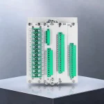
- Chassis Structure: Standard embedded metal cabinet with physical isolation between strong powe
Application Scenarios
- Application: Suitable for feeder switchgear, overhead lines, cable feeders and plant outgoing circuits with rated voltage up to 35 kV.
- Applicable Power Systems: Ungrounded, resistance-grounded and arc suppression coil neutral distribution systems (consult the manufacturer for solidly grounded systems)
- Installation Modes: Embedded local mounting in feeder cabinets, centralized panel mounting in main control rooms
- Application Sites: Urban & rural distribution substations, industrial & mining power rooms, park power distribution rooms, distributed PV booster stations, digital intelligent distribution substations
Core Product Features
- Dedicated feeder protection scheme integrating instantaneous overcurrent, directional element and composite voltage blocking, equipped with complete residual, inverse time and auto-reclosing functions. Three IEC standard inverse time curves are available, and independent soft enable switches for all protections support flexible upstream & downstream feeder time grading coordination.
- Integrated circuit breaker control loop with switchable dual-coil anti-trip function and position supervision, compatible with all 0.2~6A trip/closing coils for electromagnetic and permanent magnet actuators.
- Full-range secondary circuit monitoring, capable of identifying single/two-phase PT breakage and trip/closing circuit faults, and sending real-time alarms to eliminate hidden secondary circuit risks in advance.
- Complete fault data storage system with 32 fault recording files (4 pre-fault and 6 post-fault cycles recorded) and multi-type event logs, facilitating fault analysis and daily operation maintenance.
- Dual Ethernet + RS485 redundant communication, supports Modbus and IEC 103 protocols, and is compatible with IRIG-B, SNTP substation-wide time synchronization schemes.
- Full-color Chinese LCD HMI with hierarchical menus, supports setting copy, CB trip & close test and waveform check; all on-site commissioning can be completed without background SCADA workstation.
- Compact fully-sealed metal cabinet with physical isolation between strong power and weak signal circuits, wide temperature range and high EMC resistance, suitable for indoor feeder cabinets and outdoor cabinet transformers.
- Real-time full hardware self-diagnosis covering memory, AD, communication and output circuits, with local LED alarm indication and remote fault upload for real-time equipment status monitoring.


