What Protection Functions Should an 11kV Line Protection Relay Be Equipped With?
Document Type: Technical Articles
Document Published: 2026-08-04
Last Updated: 2026-08-13
- Applicable to: 11kV outgoing feeder circuits in industrial, mining and new‑energy power plants (including photovoltaic stations).
- Classification: Mandatory standard features vs. project‑selectable optional functions, covering protection, measurement & control, alarming and communication.
- Purpose: This document outlines the protection functions that should be considered for 11kV outgoing feeder circuits in industrial, mining and new‑energy applications. Functions are classified into mandatory standard features and project‑selectable options.Now we will elaborate on how to configure line protection for 11 kV incoming and outgoing switchgears.
I. Protection Functions
1.1 Mandatory Standard Features
- (ANSI 50) Instantaneous Overcurrent Protection – Instantaneous trip for severe phase‑to‑phase short‑circuit faults (no intentional time delay)
- (ANSI 51) Definite‑time Overcurrent Protection Stage I – Short‑time‑delay trip for near‑end downstream phase‑to‑phase short‑circuit faults
- (ANSI 51) Definite‑time Overcurrent Protection Stage III – Back‑up protection for phase‑to‑phase faults with time‑delayed trip
- (ANSI 51) Inverse‑time Overcurrent Protection – Supports IEC‑standard inverse‑time characteristic curves (e.g. NI, VI, EI and extremely inverse); independently settable and co‑ordinated with definite‑time stages
- (ANSI 51N) Zero‑sequence Definite‑time Overcurrent Protection – For single‑phase earth‑fault detection; in isolated or compensated neutral systems, configurable as alarm‑only or trip mode
- (ANSI 51N) Zero‑sequence Inverse‑time Overcurrent Protection – Inverse‑time characteristic for earth‑fault protection
- (ANSI 49) Overload Protection – Overload alarm with configurable trip function
- (ANSI 79) Auto‑reclosing Protection – Mandatory for overhead‑line circuits; shall be disabled for cable‑only circuits and underground mine feeders. The reclosing logic shall include charging condition supervision and dead‑line/live‑bus plus synchro‑check functions to prevent out‑of‑phase reclosing
1.2 Project‑Selectable Optional Features
- (ANSI 50HS) Post‑reclose Accelerated Protection – Within a short time window (e.g. 200 ms) after a closing command, overcurrent protection is automatically accelerated to instantaneous (no intentional delay) operation to clear permanent faults when closing onto a faulty line; also applicable for manual‑close acceleration
- (ANSI 27) Undervoltage Protection – Trips upon excessively low busbar voltage (requires PT input)
- (ANSI 59) Overvoltage Protection – Configurable for alarm and/or trip upon overvoltage
- PT Disconnection Detection & Alarm (60FL / VTFF) – Detects PT circuit abnormalities (fuse failure / wiring disconnection); automatically blocks all voltage‑dependent protection functions (e.g. 27, 59, 81) to prevent maloperation
- (ANSI 46) Negative‑sequence Overcurrent Protection – Protects against unbalanced loads, phase loss and asymmetrical fault conditions (e.g. turn‑to‑turn faults)
- (ANSI 81) Under‑frequency Load‑shedding – Sheds preselected loads when system frequency drops below setpoint (requires precise frequency measurement, ±0.01 Hz)
- Switch‑onto‑Fault Protection (SOTF) – Activated within an extremely short time window immediately following a closing command; if a fault exists on the line at the instant of closing, the relay trips instantaneously without intentional delay
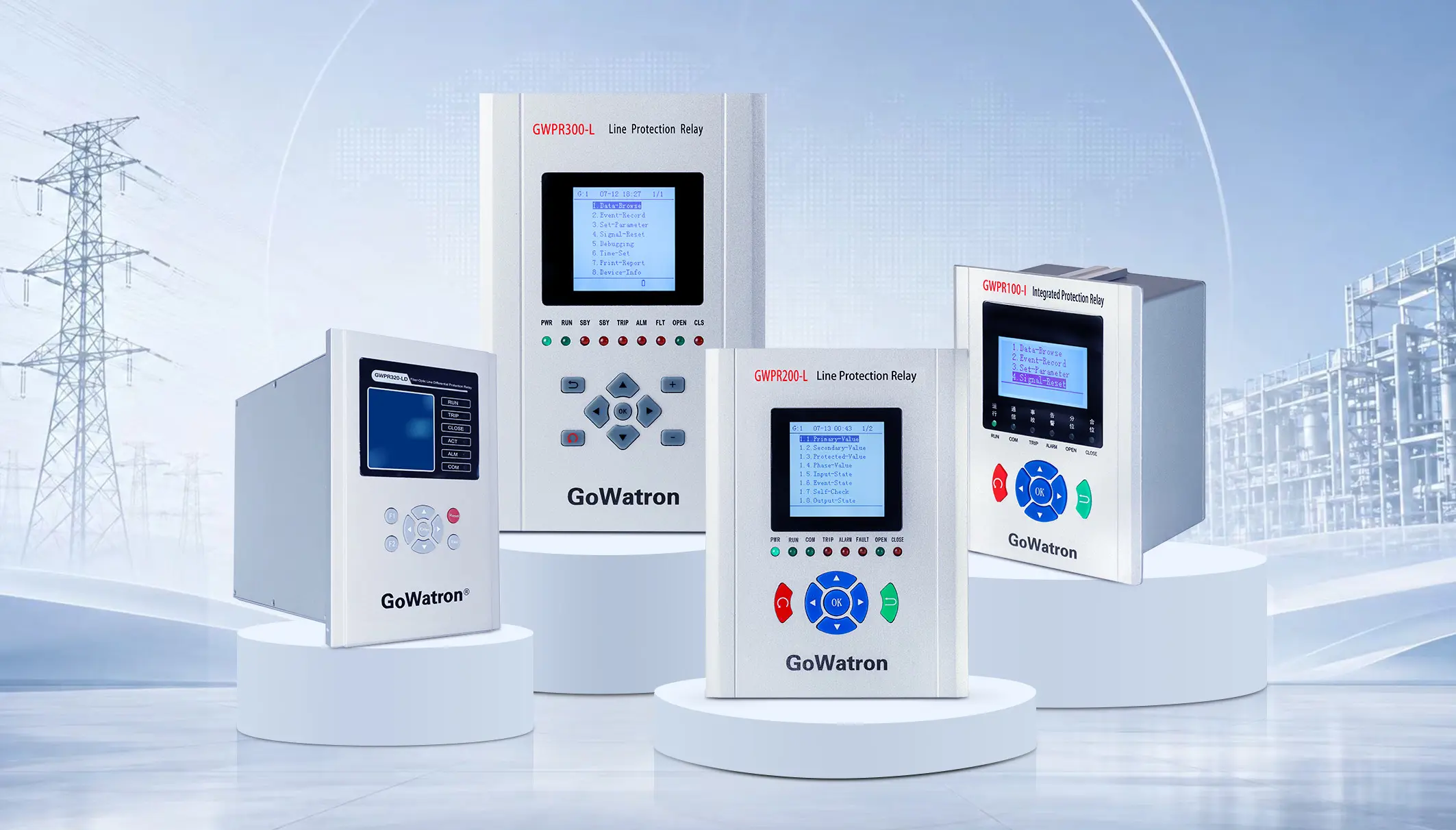
Product Recommendation
The GWPR100‑I Integrated Protection Relay is fully compliant with all mandatory protection functions specified above for 11kV feeder applications. The device integrates protection, measurement and control in one unit with high EMC immunity level (meeting IEC 60255‑1 Class 4). It is particularly well‑suited for complex industrial sites including mines, factories and photovoltaic power stations, and can be directly mounted in medium‑voltage switchgear panels to fulfil complete protection, measurement and control requirements for feeder circuits.
II. Measurement & Control Functions
2.1 Analog Quantity Measurement
- Phase voltages: UA, UB, UC
- Line voltages: UAB, UBC, UCA
- Phase currents: IA, IB, IC
- Active power P, Reactive power Q, Power factor cosφ
- System frequency F (accuracy: ±0.01 Hz if under‑frequency protection is enabled; frequency measurement is provided as a standard analog input)
2.2 Energy Metering
- Forward active energy (kWh import) – for load consumption metering
- Reverse active energy (kWh export) – for reverse power flow scenarios (e.g. PV stations)
- Forward reactive energy (kvarh import)
- Reverse reactive energy (kvarh export)
2.3 Remote Indication (Status Inputs)
Acquires the following dry‑contact status inputs:
- Circuit‑breaker position (open/closed)
- Withdrawable truck position (test/service)
- Earthing‑switch status (open/closed)
- Spring‑charging status (charged/discharged)
- Cabinet‑door status (open/closed)
2.4 Remote Control Outputs
- Circuit‑breaker closing command (relay output)
- Circuit‑breaker tripping command (relay output)
2.5 Alarm Relay Contacts
Provides hard‑contact outputs for:
- Device self‑diagnostic fault alarm
- Protection operation event (general trip/alarm)
III. Recording & Event Functions
- SOE (Sequence of Events) Recording – Time‑stamped event logging with resolution ≤ 1 ms
- Fault Recording (Waveform Capture) – Pre‑fault (5 cycles) and post‑fault (15 cycles) waveform storage for fault analysis
- Fault Report Storage – Stores fault type, operating values and time stamps
- Local HMI (LCD Panel) – Graphic LCD display with on‑site parameter setting via keypad; supports two‑level password protection (user/engineer)
IV. Communication Interfaces
- Modbus‑RTU (RS‑485) – Universal industrial serial communication with galvanic isolation and strong EMC immunity; complies with IEC 61000‑4‑5 Level 4 surge withstand capability; compatible with SCADA monitoring systems in industrial, mining and photovoltaic applications; ensures stable data transmission over long distances


