Transformer Buchholz Relay: Operating Principle, Functions and Setting Calculations
A Buchholz relay is a gas and liquid actuated relay used to protect conservator-type liquid-immersed transformers and reactors. It is installed in the pipe connecting the transformer main tank to the conservator.
In accordance with IEC terminology, a Buchholz relay is intended to detect:
- Gas release from the protected equipment;
- Liquid surge from the main tank towards the conservator;
- Complete loss of insulating liquid.
It normally provides a gas accumulation alarm for slowly developing faults and a liquid-surge trip for severe internal faults. Buchholz protection is generally associated with ANSI Device 63.
Buchholz relays are primarily used on conservator-type liquid-immersed transformers. They are not normally applicable to dry-type or hermetically sealed transformers.
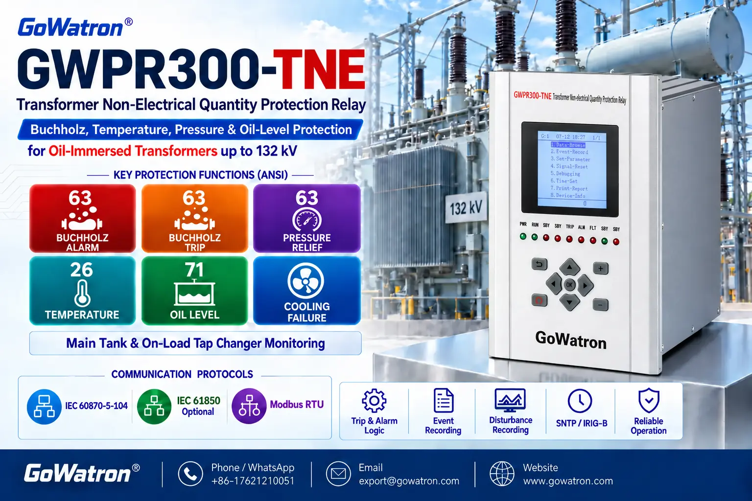
1. Functions of Buchholz Protection
| Protection stage | Detected condition | Typical output | Typical faults or abnormal conditions |
| Gas accumulation stage | Gas release, gas accumulation or gradual liquid loss | Alarm | Local overheating, partial discharge, minor insulation faults, liquid leakage or trapped air |
| Liquid-surge stage | Sudden liquid surge towards the conservator | Trip | Severe interturn faults, internal earth faults, internal arcing or other major internal faults |
| Complete liquid-loss detection | Serious reduction or complete loss of insulating liquid | Alarm and/or trip, depending on the relay design and protection scheme | Major leakage or failure of the transformer liquid system |
1.1 Gas Accumulation Alarm
A slowly developing internal fault may cause the insulating liquid or solid insulation to decompose and release gas. The gas enters the Buchholz relay and accumulates in its upper chamber, displacing the insulating liquid and lowering the upper float.
When the accumulated gas reaches the specified operating volume, the upper switching element operates and initiates an alarm.
Typical causes include:
- Local overheating of windings or leads;
- Poor electrical connections;
- Minor interturn faults;
- Partial discharge;
- Insulating-liquid leakage;
- Air remaining after filling, filtration or maintenance.
1.2 Liquid-Surge Trip
A severe internal fault may rapidly generate gas and cause a sudden surge of insulating liquid from the transformer main tank towards the conservator.
When the liquid-surge velocity reaches the calibrated operating value, the vane or lower switching element operates. The trip contact then initiates the tripping of the required transformer circuit-breakers.
Typical causes include:
- Severe interturn short-circuits;
- Internal winding-to-earth faults;
- Internal arcing in windings or leads;
- Severe core overheating or damage;
- Other major faults inside the transformer main tank.
An on-load tap-changer normally has a separate liquid-surge relay or protective device. Its protection must be independent of the Buchholz protection for the transformer main tank.
2. Operating Principle
Under normal operating conditions, the Buchholz relay is filled with insulating liquid. The alarm and trip contacts remain in their normal positions.
For a slowly developing fault:
Internal fault → Gas release → Gas accumulation → Falling liquid level → Alarm contact operation
For a severe internal fault:
Internal fault → Rapid gas release and liquid surge → Trip contact operation → Transformer trip
For substantial liquid loss:
Liquid leakage → Falling liquid level → Float operation → Alarm and/or trip
The actual response to liquid loss depends on the relay design and the project protection scheme
3. Setting Principles
Buchholz protection is not set according to transformer rated current or calculated short-circuit current. Its mechanical operating values are established and calibrated for the particular relay design.
The principal settings and configuration items include:
- Gas accumulation operating volume;
- Liquid-surge operating velocity;
- Gas accumulation alarm delay;
- Liquid-surge trip delay;
- Alarm and trip output logic;
- Signal latching and reset logic.
The final settings must be based on:
- Transformer construction and rating;
- Transformer cooling type, such as ONAN, ONAF, OFAF or ODAF;
- Relay nominal size and pipe diameter;
- Buchholz relay type;
- Approved technical documentation;
- Project protection philosophy;
- Factory and site test results.
4. Gas Accumulation Alarm Settings
4.1 Gas Accumulation Operating Volume
The alarm operating value is normally expressed as the accumulated gas volume required to operate the upper switching element:
\[ V_{\mathrm{set}}=V_{\mathrm{gas}} \]
where:
- \( V_{\mathrm{set}} \)is the gas accumulation setting;
- \( V_{\mathrm{gas}} \) is the gas volume required for operation.
For many commonly used Buchholz relay designs, the gas accumulation operating volume is approximately:
\[ V_{\mathrm{set}}=150\text{–}300\ \mathrm{cm^3} \]
The actual operating volume depends on the relay type, nominal size and construction. The operating value stated in the approved transformer and Buchholz relay documentation must take precedence over any general reference range.
4.2 Gas Accumulation Alarm Delay
The gas accumulation stage normally initiates an alarm. A short confirmation delay may be applied in the numerical protection device to prevent operation caused by contact bounce:
\[ t_{\mathrm{alarm}}=0\text{–}1.0\ \mathrm{s} \]
A typical setting example is:
\[ t_{\mathrm{alarm}}=0.5\ \mathrm{s} \]
An instantaneous alarm may also be used when the input contact is stable and the project specification does not require a delay.
5. Liquid-Surge Trip Settings
5.1 Liquid-Surge Operating Velocity
The liquid-surge operating value is calibrated according to the Buchholz relay type, nominal size and transformer application.
Frequently specified operating velocities include:
\[ v_{\mathrm{set}}=0.65,\ 1.0,\ \text{or}\ 1.5\ \mathrm{m/s} \]
Depending on the relay design and application, other calibrated operating values may also be available.
The selected operating value must take account of:
- Buchholz relay type;
- Nominal pipe diameter;
- Transformer construction and rating;
- Transformer cooling type, such as ONAN, ONAF, OFAF or ODAF;
- Normal oil-circulation conditions;
- Approved project documentation;
- Factory and site test results.
Transformers with forced-oil cooling can have higher normal oil-circulation velocities than naturally cooled transformers. The selected operating value must remain secure under the maximum normal oil-flow condition while retaining adequate sensitivity to an internal fault.
The calibrated operating value must not be replaced by a value obtained solely from a pipe-flow calculation.
5.2 Average Pipe-Flow Calculation
If the volumetric flow rate and internal pipe diameter are known, the average liquid velocity in the pipe can be calculated as:
\[ v_{\mathrm{avg}}=\frac{Q}{A} \]
The internal cross-sectional area of the pipe is:
\[ v_{\mathrm{avg}}=\frac{Q}{A} \]
Therefore:
\[ v_{\mathrm{avg}}=\frac{4Q}{\pi D^2} \]
where:
- \( v_{\mathrm{avg}} \) is the average liquid velocity in m/s;
- \( Q \) is the volumetric flow rate in m³/s;
- \( A \)is the internal cross-sectional area of the pipe in m²;
- \( D \)is the internal pipe diameter in m.
This equation calculates the average liquid velocity in the pipe. It does not directly determine the calibrated operating value of the Buchholz relay.
The actual relay response is also affected by:
- Vane geometry;
- Internal flow passages;
- Velocity distribution;
- Installation arrangement;
- Calibration method.
5.3 Calculation Example
For a Buchholz relay installed on a DN80 connection, assume:
- Internal pipe diameter: \( D=80\ \mathrm{mm}=0.08\ \mathrm{m} \);
- Volumetric flow rate: \( Q=0.005\ \mathrm{m^3/s} \).
The internal cross-sectional area is:
\[ A=\frac{\pi\times0.08^2}{4} =0.00503\ \mathrm{m^2} \]
The average liquid velocity is:
\[ v_{\mathrm{avg}} =\frac{0.005}{0.00503} \approx1.0\ \mathrm{m/s} \]
Therefore, the average pipe-flow velocity is approximately:
\[ v_{\mathrm{avg}}\approx1.0\ \mathrm{m/s} \]
This result is a hydraulic calculation only. It must not be used directly as the Buchholz relay setting unless it agrees with the approved calibrated operating value.
5.4 Liquid-Surge Trip Delay
Because a liquid surge may indicate a severe internal transformer fault, the liquid-surge stage normally initiates an instantaneous trip:
\[ t_{\mathrm{trip}}=0\ \mathrm{s} \]
If contact-debounce supervision is required in a numerical protection device, a very short confirmation time may be applied:
\[ t_{\mathrm{trip}}=0.02\text{–}0.10\ \mathrm{s} \]
Any intentional delay must comply with the project protection philosophy and transformer protection requirements.
6. Typical Setting Example
The following values are provided only as an example for a representative Buchholz relay with a DN80 connection.
| Setting item | Typical example | Output |
| Gas accumulation operating volume | 250 cm³ | Alarm |
| Gas accumulation alarm delay | 0.5 s | Alarm and event recording |
| Liquid-surge operating velocity | 1.0 m/s for DN80 | Trip |
| Liquid-surge trip delay | 0 s | Trip the required circuit-breakers |
| Complete liquid-loss response | Relay- and scheme-dependent | Alarm and/or trip |
| Trip logic | Latched trip | Trip and automatic-reclosing blocking |
| Reset method | Manual reset | Retain fault indication |
These values are examples only. Project settings must be based on the approved transformer data, Buchholz relay data and protection documentation.
7. Protection Logic
Gas accumulation alarm logic:
\[ \text{Gas accumulation contact} + \text{Alarm delay} \rightarrow \text{Alarm} \]
Liquid-surge trip logic:
\[ \text{Liquid-surge contact} + \text{Trip delay} \rightarrow \text{Transformer trip} \]
The liquid-surge trip signal may also:
- Trip the required transformer circuit-breakers;
- Block automatic reclosing;
- Latch the trip indication;
- Generate a sequence-of-events record;
- Transmit the alarm and trip status to the SCADA or substation automation system.
8. Installation and Commissioning Requirements
- The flow-direction arrow on the Buchholz relay must point towards the conservator.
- The connecting pipe must be installed with the upward inclination specified in the approved transformer installation drawings.
- The pipe arrangement must allow gas released in the main tank to travel freely towards the Buchholz relay.
- The transformer main-tank Buchholz relay and the on-load tap-changer protective device must use separate protection logic.
- The gas accumulation stage normally initiates an alarm, while the liquid-surge stage normally initiates a trip.
- Trapped air must be released after liquid filling, filtration or maintenance.
- Following a liquid-surge trip, the transformer must not be re-energised until the cause has been identified and the required inspections and tests have been completed.
- The alarm contact, trip contact, calibrated operating values, wiring and trip circuit must be verified during commissioning.
Buchholz protection is sensitive to both slowly developing and severe internal faults in conservator-type liquid-immersed transformers. For important transformers, it is normally applied together with transformer differential protection (ANSI 87T) to provide comprehensive internal-fault protection.


