How to Select Substation DC Power Supply System Panel Capacity and Charger Modules
- The DC power supply system is the “last line of defence” in a substation. When all AC auxiliary power sources are lost, the DC system enables protection relays to operate, circuit breakers to trip, and signalling circuits to remain functional. Improper sizing leads to tangible consequences: premature battery ageing, insufficient backup duration, inadequate closing capability, frequent alarms, and even equipment failure and downtime.
- This article refers to IEC TS 63346-2-2:2026, Low-voltage auxiliary power systems – Part 2-2: Design criteria – Low-voltage DC auxiliary power systems for substations, and combines it with commonly used engineering design methods for substation DC systems to present the battery capacity and charger selection procedure. It should be noted that this document is a Technical Specification. Its scope covers the configuration of DC power sources, system wiring, electrical equipment selection and physical layout. However, the specific engineering values in this article must be determined in conjunction with local regulations, the client’s technical specifications, and manufacturer data.
1. Determining the Nominal DC System Voltage
- The first step in capacity selection is to determine the nominal DC system voltage. Common nominal DC system voltages in substations include DC 110 V, DC 125 V, and DC 220 V. In Chinese engineering practice, DC 220 V is often used for higher-voltage substations, while DC 110 V is commonly used for small and medium-sized substations. However, there is no globally mandated correspondence between the two. The final choice depends on local grid codes and the client’s technical specifications, the rated voltage of circuit-breaker trip and closing coils, the power supply requirements of protection and communication equipment, cable length and permissible voltage drop, the number of battery cells, and the earthing arrangement.
2. DC Load Inventory and Classification
- Load inventory is the basis for battery capacity calculation. IEC TS 63346-2-2 states that the scope of a DC auxiliary power system covers everything from the low-voltage AC input of the charger to the DC input terminals of the loads.
- IEEE 485 typically classifies loads into continuous loads, noncontinuous loads, and momentary loads. In practical engineering inventory, noncontinuous loads may be further subdivided by emergency duration into emergency-duration loads and short-duration loads. The classification is as follows:
- Continuous loads: Loads that run continuously under both normal and emergency conditions, such as protection relays, control devices, communication equipment, monitoring equipment, and DC bus monitoring devices.
- Emergency-duration loads (a practical subdivision of noncontinuous loads): Loads that must be maintained for a certain period during loss of AC power, such as emergency lighting, inverter power supplies, and communication power supplies.
- Short-duration loads (a practical subdivision of noncontinuous loads): Loads lasting from several seconds to several minutes.
- Momentary loads: Circuit-breaker trip coils, closing coils, motor-operated mechanism starting currents, etc.
- It should be particularly noted that circuit-breaker closing is not the only momentary load that must be considered; circuit-breaker tripping is even more critical. One of the most fundamental safety functions of a DC system is to ensure that protection operates and the circuit breaker reliably trips even at the end of the specified battery duty cycle.
3. Determining the Emergency Backup Duration
- The emergency backup duration should be determined based on local standards and utility requirements, whether the substation is attended or unattended, the reliability of the available AC auxiliary supplies, the start-up and connection time of any emergency generator, the response time of operation and maintenance personnel, and the required operating duration of protection, communication and automation systems.
- A commonly used emergency backup duration in engineering practice is 1 to 2 hours. Unattended, remote, or high-reliability projects may require longer durations.
- For 35–110 kV substations within the scope of GB 50059-2011, the battery capacity of an attended substation is required to support the specified station DC loads for 1 hour following loss of AC auxiliary power, while an unattended substation is required to support them for 2 hours. Other voltage levels and overseas projects shall comply with the applicable industry standards, local regulations and the client’s technical specifications.
4.Battery Capacity Calculation: Stepwise Current Method
- The stepwise current method, also known as the stage‑by‑stage capacity calculation method, is a commonly‑used method for substation battery capacity calculation. It divides the emergency discharge process into multiple time stages, calculates the required capacity stage‑by‑stage, and takes the maximum value from all stage results.
- Taking an example system with a 2‑hour emergency backup duration, the discharge process can be divided into M₁ (0–1 min), M₂ (1 min to 60 min), and M₃ (60 min to 120 min). Stage division shall be determined according to the application scenario, load switching sequence and duration of each individual load. Not all projects require the three stages described above.
- Multi‑stage capacity calculation must account for: the load current at each stage, the duration of each load stage, the current increment or difference between successive stages, the end‑of‑discharge voltage, ambient temperature, battery type, and the capacity conversion factor or constant‑power / constant‑current discharge data provided by the manufacturer.
Using the stepwise load method, the required battery capacity up to stage j is calculated as follows:
\[ C_{\mathrm{req},j}=K_{It}\sum_{i=1}^{j}\frac{\Delta I_{i}}{K_{c}(t_{ij},U_{f})} \]
Where:
- \( C_{\mathrm{req},j} \)— Required battery capacity up to stage\( j \), Ah;
- \( K_{It} \) — Overall correction factor covering temperature, ageing, and design margin;
- \( \Delta I_i \) — Current increment corresponding to load step\( i \), A;
- \( K_c \) — Capacity conversion factor provided by the battery manufacturer at a specified reference temperature for discharge time \( t_{ij} \) and end‑of‑discharge voltage \( U_f \), in A/Ah;
- \( t_{ij} \)— Discharge time from the start of load stage i to the end of stage j, min;
- \( U_f \)— Specified end‑of‑discharge voltage, V.
It should be noted that different standards, design manuals, and manufacturer data may define the capacity conversion factor differently. In this article, \( K_c \) is expressed in A/Ah and is therefore used as a divisor. If the manufacturer provides the factor in Ah/A, it shall be used as a multiplier. The actual calculation must follow the definition of the factor in the referenced source. If the manufacturer’s capacity conversion factor has already been corrected for the project’s minimum design temperature, the temperature factor shall not be counted again in the overall correction factor.
Taking the first stage of a 220 V DC system as an example: load current\( I_1 = 54.4 \)A, capacity conversion factor \( K_{c1}=1.24 \)A/Ah, and overall correction factor \( K_{It}=1.4 \). The first‑stage calculated capacity is:
\[ \frac{54.4\ \mathrm{A}}{1.24\ \mathrm{A/Ah}} = 43.87\ \mathrm{Ah}C_{c1}=1.4\times 43.87 = 61.4\ \mathrm{Ah} \]
- However, this value represents only the first load stage and does not represent the complete capacity calculation. The cumulative capacity for subsequent stages must be calculated in accordance with the formula above, and the maximum value among all stages shall be taken.
- Important note: The capacity conversion factor must be based on discharge data provided by the selected battery manufacturer at the specified end‑of‑discharge voltage and temperature. It must not be directly applied from another battery model. IEC 60896‑21 specifies test methods for stationary valve‑regulated lead‑acid batteries and can be used to evaluate performance such as capacity. The engineering capacity of the battery shall still be calculated based on the load profile, specified discharge time, end‑of‑discharge voltage, ambient temperature, and manufacturer discharge data.
- After the required capacity has been calculated, the next higher available standard battery rating shall be selected from the manufacturer’s product range, for example 100 Ah, 150 Ah, 200 Ah, 250 Ah, 300 Ah or 400 Ah. The calculated capacity shall not be rounded down.
5. Determining the Overall Correction Factor
- The overall correction factor \( K_R \) must cover temperature correction, ageing margin, and design margin. A typical example: temperature correction factor 1.1, ageing factor 1.1, design margin 1.15. The product is approximately 1.39, and 1.4 is commonly used in engineering as an example value.
- However, it must be emphasized that 1.4 cannot be used as a fixed value for all projects. The temperature factor depends on the minimum design temperature and battery type; the ageing margin depends on the end‑of‑life capacity requirement; the design margin depends on future expansion and load uncertainty; and the manufacturer’s discharge data may already include certain temperature conditions, so repeated multiplication of factors would result in double correction. The overall correction factor should be determined based on the minimum ambient temperature, end‑of‑life capacity, future expansion margin, and manufacturer discharge data.
6. Momentary Load Verification
- After the required ampere-hour capacity has been determined using the stepwise load method, the momentary current associated with circuit-breaker tripping, circuit-breaker closing or motor-operated mechanism starting shall be superimposed at the most onerous point in the duty cycle to verify that the battery terminal voltage and load terminal voltage remain above the minimum operating voltage of the equipment.
- Momentary loads cannot be handled simply by adding a certain number of ampere-hours to the capacity. Short-duration high currents such as circuit-breaker tripping and closing are typically verified by focusing on: the instantaneous output capability of the battery at the end of the emergency discharge, the battery terminal voltage under momentary current, the minimum permissible voltage at the DC bus and load terminals, feeder cable voltage drop, the number of simultaneously operating circuit breakers, and the capability of the battery to supply the load alone when the charger is out of service.
Charger Capacity and Module Quantity Selection
Once the battery capacity is determined, the charger can be selected. The charger shall be capable of carrying the normal continuous load and recharging the discharged battery within the specified recovery time. For batteries requiring equalizing or boost charging, the corresponding charging condition shall also be verified. The charger output current shall satisfy:
\[ I_{\mathrm{charger}} \ge I_{\mathrm{continuous}} + I_{\mathrm{battery\ recharge}} \]
Where:
- \( I_{\mathrm{charger}} \)— Rated charger output current, A;
- \( I_{\mathrm{continuous}} \) — Normal continuous load current of the substation, A;
- \( I_{\mathrm{battery\ recharge}} \)— Battery recharge current, A.
The battery recharge current shall be determined based on battery capacity, permissible charging current, required recovery time, battery type, and manufacturer charging curve.
Assume the battery recharge current is taken as the 10‑hour rate current\( I_{10} \). For a battery with rated capacity \( C_{10}=200\ \mathrm{Ah} \):
\[ I_{10}=\frac{C_{10}}{10\ \mathrm{h}}=\frac{200\ \mathrm{Ah}}{10\ \mathrm{h}}=20\ \mathrm{A} \]
\[ I_{\mathrm{battery\ recharge}} = I_{10}=20\ \mathrm{A} \]
With a continuous load of 10 A, the minimum required charger output current is:
\[ I_{\mathrm{charger}} = I_{\mathrm{continuous}} + I_{\mathrm{battery\ recharge}} = 10 + 20 = 30\ \mathrm{A} \]
(In battery industry notation, the 10‑hour rate current corresponds to 0.1C; for a 200 Ah battery, its value is 20 A. For formal calculations, $$C_{10}/10\ \mathrm{h}$$ is recommended to ensure dimensional consistency.)
When 10 A charger modules are used, 3 working modules are required. With N+1 redundancy, 4 modules are configured in total. If any one module is taken out of service, the remaining 3 modules can still provide 30 A output. The actual permissible charging current, required battery recovery time, and redundancy method shall be based on the battery manufacturer’s data and the project specification.
It is also necessary to verify that after AC input is restored, the charger can both carry the continuous load and restore the battery capacity within the specified time.
For some valve‑regulated lead‑acid (VRLA) batteries, equalization charge is not a routine operation performed at fixed intervals. The terms boost charge, recharge, or equalizing charge should be used in accordance with the battery manufacturer’s requirements. It should not be assumed that all VRLA batteries require periodic equalizing charge.
8. Example Engineering Configurations
- The following table is intended only to illustrate possible product specification combinations. It does not represent IEC-mandated values and cannot replace actual load calculations. Different countries, substation sizes, system configurations, numbers of circuit breakers, communication loads, and emergency backup durations will all affect the final capacity.
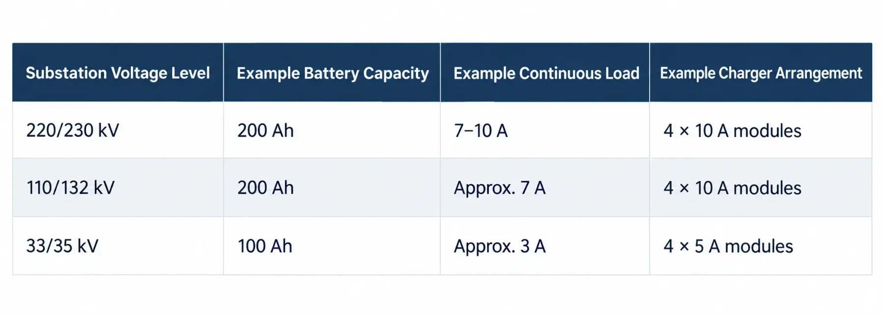
- For substations with high reliability requirements, two independent DC power supply systems may be provided. The two battery banks and their associated chargers should normally operate independently and should not remain connected in parallel. Where a DC bus-tie or emergency transfer function is provided, appropriate electrical interlocking shall be incorporated in accordance with the project design requirements.
Summary
- Substation DC power supply system sizing is a chain of interlinked steps: determine DC voltage → establish load inventory → develop DC duty-cycle load profile → determine backup duration → calculate battery capacity → verify momentary current and minimum voltage → select charger → configure redundant modules. Each step must be based on actual equipment parameters and applicable standards. Sample parameters or previous project practices must not be copied directly. Proper sizing directly determines whether protection relays operate correctly and whether circuit breakers reliably trip under substation emergency conditions.


