Substation Protection Relays : Types, Functions & Selection Guide
1. What Are Substation Protection Relays?
- Substation protection relays are essential components of electrical power system protection. They monitor the operating conditions of transmission lines, power transformers, busbars, capacitor banks and other electrical equipment within substations. When faults or abnormal conditions occur, such as short circuits, earth faults, overloads, abnormal voltages or frequency deviations, protection relays issue alarm or trip commands according to predefined protection settings and logic.
- Modern digital protection relays typically integrate protection, measurement, control, event recording, disturbance recording and communication functions. They can operate alongside substation automation systems (SAS) and supervisory control and data acquisition (SCADA) systems to support equipment monitoring, remote control and fault analysis.
- In China and other markets adopting IEC standards, protection relays are widely used in substations operating at 11 kV, 33 kV, 66 kV, 110 kV, 132 kV and 220 kV.
- Different voltage levels, primary equipment configurations and system earthing arrangements impose different requirements on protection functions, operating speed, selectivity and reliability.
- Terminology note: This article follows British English and IEC oriented terminology. The term earth fault is equivalent to ground fault in North American terminology, while earthing corresponds to grounding. The spelling pickup is used consistently for protection thresholds and operating conditions.
The primary functions of substation protection relays include:
- Fault detection: Identifying phase to phase short circuits, earth faults, overloads and other abnormal operating conditions.
- Selective fault isolation: Disconnecting the faulty equipment or section while minimising interruptions to healthy parts of the network.
- Fast operation: Reducing fault clearance times while maintaining appropriate protection coordination.
- Equipment protection: Limiting equipment damage caused by fault currents and abnormal operating conditions.
- Operational monitoring: Providing information on current, voltage, power, frequency and equipment status.
- Automation integration: Exchanging operational data with SAS, SCADA and other automation equipment through supported communication protocols.
Protection relays do not normally interrupt primary fault currents directly. Instead, they issue trip commands through the trip circuit to operate the circuit breaker.
Reliable fault clearance therefore depends not only on the protection relay but also on the circuit breaker, DC auxiliary power supply, instrument transformers and associated protection circuits.
2. How Do Substation Protection Relays Work?
- Substation protection relays acquire electrical measurements through current transformers (CTs), voltage transformers (VTs) and other signal interfaces.
- The relays process these signals and determine whether a fault or abnormal condition exists by comparing calculated electrical quantities against protection settings and logic criteria.
2.1 Basic Operating Principle
The typical operating sequence is:
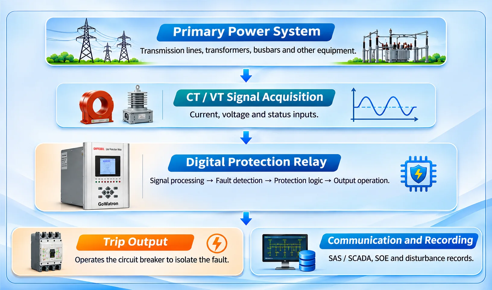
2.2 Signal Acquisition and Fault Detection
- Protection relays receive current and voltage signals from CTs and VTs.
- After input conditioning, analogue-to-digital conversion and digital signal processing, the relays calculate electrical quantities such as RMS current, RMS voltage, frequency, phase angle and symmetrical components.
Different protection functions use different operating principles:
- Overcurrent protection: Compares measured current against the configured pickup setting.
- Differential protection: Evaluates the vector relationship between currents entering and leaving a defined protection zone.
- Distance protection: Calculates the apparent impedance measured by the relay using voltage and current quantities and their phase relationship to determine whether a fault lies within the configured protection characteristic.
- Undervoltage protection: Detects when the measured voltage falls below a specified pickup threshold.
- Frequency protection: Detects frequency deviations beyond configured operating limits.
When the protection criteria are satisfied and the applicable time delays, blocking conditions and interlocking logic permit operation, the relay issues a trip command.
2.3 Fundamental Protection Requirements
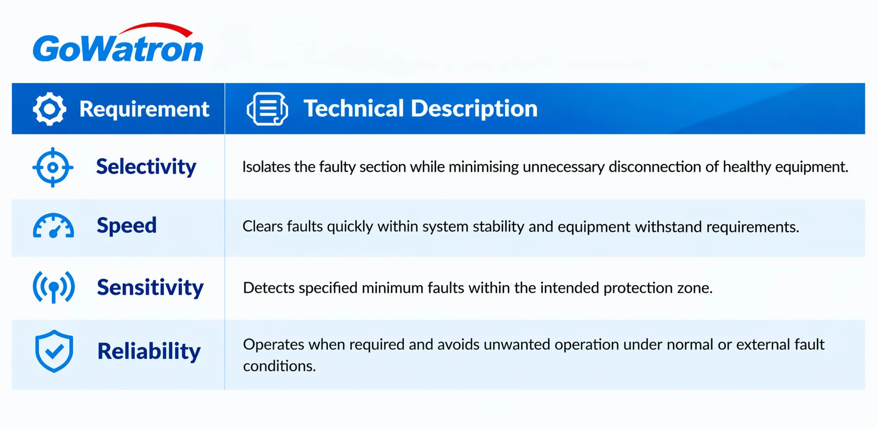
These requirements must be balanced during protection system design.
For example, increasing overcurrent protection sensitivity may increase the risk of unwanted operation during certain external faults or load conditions, while excessive operating delays may expose equipment to fault currents for longer periods.
Application of the GWPR Series
The GoWatron GWPR200, GWPR300, GWPR320, GWPR350 and GWPR400 series provide protection solutions for feeders, transformers, transmission and distribution lines, busbars, and voltage and frequency applications.
The appropriate model should be selected according to the required protection functions and project specifications rather than the product series number alon
3. Types of Substation Protection Relays
Substation protection relays can be classified according to the protected equipment and operating principles.
The main categories include line protection, transformer protection, busbar protection, feeder protection, voltage and frequency protection, capacitor bank protection and other specialised protection devices.
3.1 Line Protection Relays
Line protection relays are designed to detect and isolate short circuits and earth faults on transmission and distribution lines.
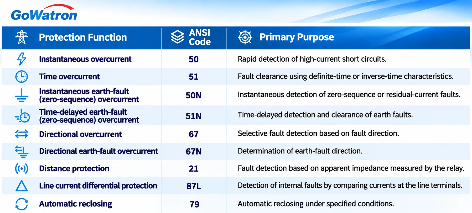
Terminology note: ANSI 50N/51N are commonly described as earth-fault overcurrent protection or zero-sequence overcurrent protection. Depending on the CT arrangement, the operating current may be obtained from a dedicated zero-sequence CT or calculated from the residual sum of the three phase currents. Manufacturer-specific 50N/51N and 50G/51G conventions should be checked during cross-manufacturer selection.
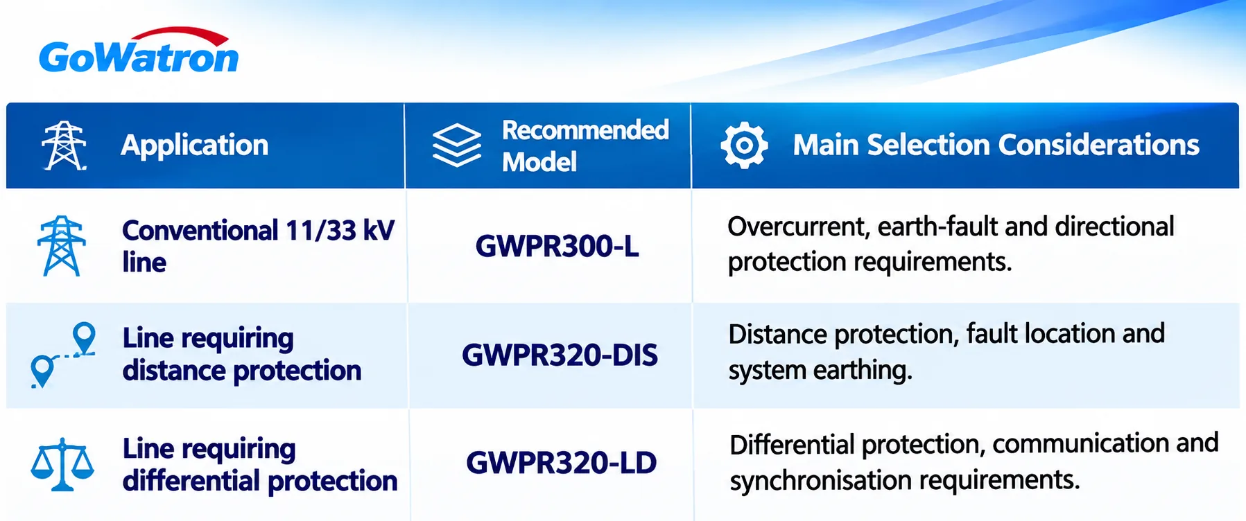
Selection Guidance
- For conventional radial 11 kV and 33 kV distribution lines, overcurrent and earth-fault protection are commonly used.
- For double-ended supplies, ring networks or systems with variable power flow directions, directional protection should be considered.
- For higher-voltage transmission lines, distance protection or line current differential protection may be selected according to line characteristics, communication availability and system requirements.
- Line differential protection generally requires a reliable communication channel between line terminals.
- Distance protection settings must account for line impedance, fault resistance, operating configurations and coordination with adjacent line protection.
Recommended GoWatron GWPR Line Protection Relays
GWPR300-L Line Protection Relay
- The GWPR300-L is a candidate for substation line bays requiring integrated line protection, measurement, control and communication functions.
- Its suitability should be confirmed against the required protection function list and the specific product configuration.
GWPR320-DIS Distance Protection Relay
- The GWPR320-DIS is intended for applications requiring distance protection (21/21N), fault location, overcurrent protection and directional protection.
- The published product information primarily addresses specific distribution network applications up to 35 kV. Suitability for higher-voltage transmission lines must therefore be confirmed separately.
GWPR320-LD Line Differential Protection Relay
- The GWPR320-LD is intended for applications requiring line current differential protection (87L).
- Selection should consider the terminal equipment configuration, communication channel, time synchronisation arrangements and applicable line parameters.
3.2 Transformer Protection Relays
Power transformers are critical primary assets within substations.
Transformer faults can result in equipment damage, supply interruptions and significant repair costs.
Transformer protection systems normally combine electrical protection with non-electrical protection functions.
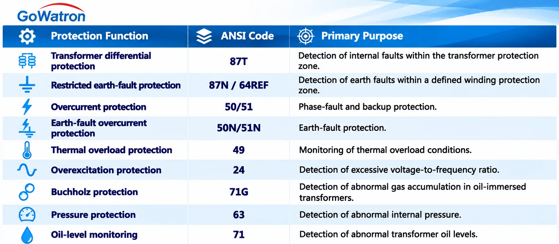
Note: 87N/64REF are manufacturer-specific or scheme-dependent designations for restricted earth-fault protection. The applicable project protection function list and manufacturer documentation should be followed.
Key Technical Considerations for Transformer Differential Protection
Transformer differential protection operates by evaluating the current differential within the defined transformer protection zone.
Because transformer windings may have different rated currents, vector groups and phase relationships, differential protection must account for:
- CT ratio matching between transformer sides.
- Transformer vector-group and phase-shift compensation.
- Zero-sequence current treatment or elimination.
- Magnetising inrush detection and blocking or restraint.
- Percentage differential restraint characteristics and high-set differential protection.
- CT saturation and CT circuit supervision.
Selection Guidance
Important power transformers should be equipped with appropriate differential and backup protection according to transformer rating, voltage level, winding arrangement and applicable engineering standards.
Where the transformer neutral earthing arrangement requires dedicated earth-fault protection, restricted earth-fault protection should also be evaluated.
Recommended GoWatron GWPR Transformer Protection Relays
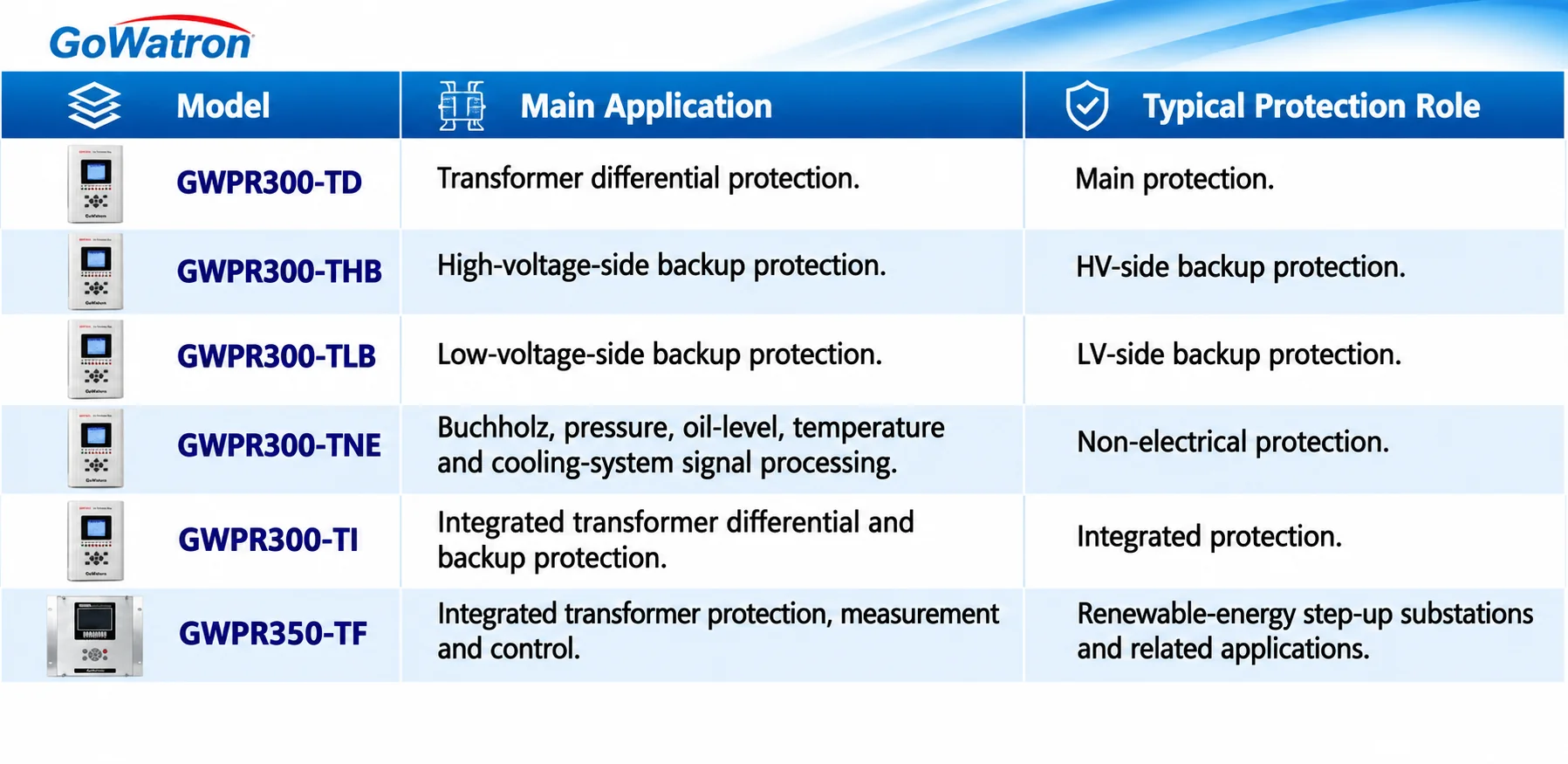
GWPR300-TD Transformer Differential Protection Relay
The GWPR300-TD is designed for transformer differential protection applications, including suitable two-winding and three-winding transformers up to 132 kV, subject to the applicable product specification.
It provides differential protection functions, including differential restraint, magnetising inrush detection, vector-group compensation and CT circuit supervision.
Recommended Configurations
- For a conventional main transformer, the GWPR300-TD can be combined with the necessary HV-side and LV-side backup protection.
- Where independent non-electrical protection is required, the GWPR300-TNE can be added.
- For transformers requiring greater functional separation and maintainability, a configuration comprising GWPR300-TD, GWPR300-THB, GWPR300-TLB and GWPR300-TNE may be considered.
- For projects with limited panel space, the GWPR300-TI combined with the GWPR300-TNE may be evaluated as an integrated solution.
- Although integrated protection can reduce the number of devices, main and backup protection functions sharing the same hardware must not be regarded as two fully independent protection systems.
3.3 Busbar Protection Relays
Busbars connect multiple electrical circuits within a substation.
A busbar fault can affect a large part of the electrical network, making fast operation, selectivity and reliability particularly important.
The principal functions include:
- Busbar differential protection (87B): Detects internal busbar faults by comparing currents associated with the defined busbar protection zone.
- Circuit-breaker failure protection (50BF): Initiates backup tripping when a circuit breaker fails to clear a fault within the specified time.
- CT circuit supervision: Detects current measurement abnormalities that could affect differential protection performance.
- Busbar zone selection and disconnector position logic: Determines the appropriate differential protection zones according to the busbar arrangement and switching-device positions.
Busbar protection must be coordinated with bus couplers, bus-section circuit breakers, incoming and outgoing circuit breakers, and disconnector positions.
Selection Guidance
- For important busbars in 110 kV, 132 kV and 220 kV substations, suitable busbar protection should be provided according to the busbar arrangement and applicable engineering standards.
- For 11 kV and 33 kV busbars, the need for dedicated busbar differential protection should be assessed against short-circuit levels, operational importance, fault clearance requirements and project economics.
Recommended GoWatron GWPR Busbar Protection Relay
GWPR350-BD Busbar Differential Protection Relay
The GWPR350-BD is intended for substation applications requiring busbar differential protection (87B).
Its configuration should be evaluated according to the busbar arrangement, number of CT circuits and required protection zones.
Important selection considerations include:
- Number of connected bays.
- Bus coupler and bus-section arrangements.
- CT saturation stability.
- Disconnector position acquisition.
- Circuit-breaker failure protection coordination.
- Protection zone selection logic.
The applicable voltage range, maximum number of connected bays and availability of circuit-breaker failure protection should be confirmed against the relevant GWPR350-BD technical documentation.
3.4 Feeder Protection Relays
Feeder protection relays are widely used for outgoing circuits in 11 kV and 33 kV medium-voltage distribution systems.
- Feeder protection relays can be installed within medium-voltage switchgear panels and connected to substation automation systems through supported communication interfaces.
- In radial distribution networks, feeder protection must normally be coordinated with upstream incoming protection, downstream protection devices and fuses using appropriate time-current characteristics.
- In distribution networks incorporating distributed generation, bidirectional fault currents, changes in network configuration and distributed-generation interconnection requirements must also be considered.
Recommended GoWatron GWPR Feeder Protection Relay
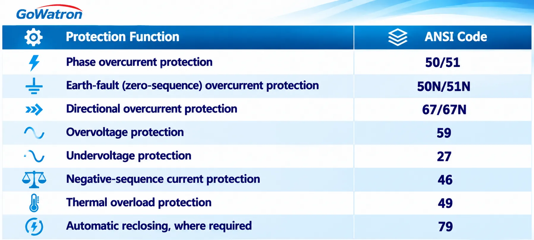
GWPR200-L Feeder Protection Relay
The GWPR200-L is designed for medium-voltage switchgear feeder applications.
Its protection functions include:
- Phase overcurrent protection (50/51).
- Earth-fault overcurrent protection (50N/51N).
- Directional overcurrent and directional earth-fault protection (67/67N).
- Overvoltage and undervoltage protection (59/27).
- Negative-sequence current protection (46).
- Thermal overload protection (49).
The relay also provides measurement, control and communication capabilities according to its configuration.
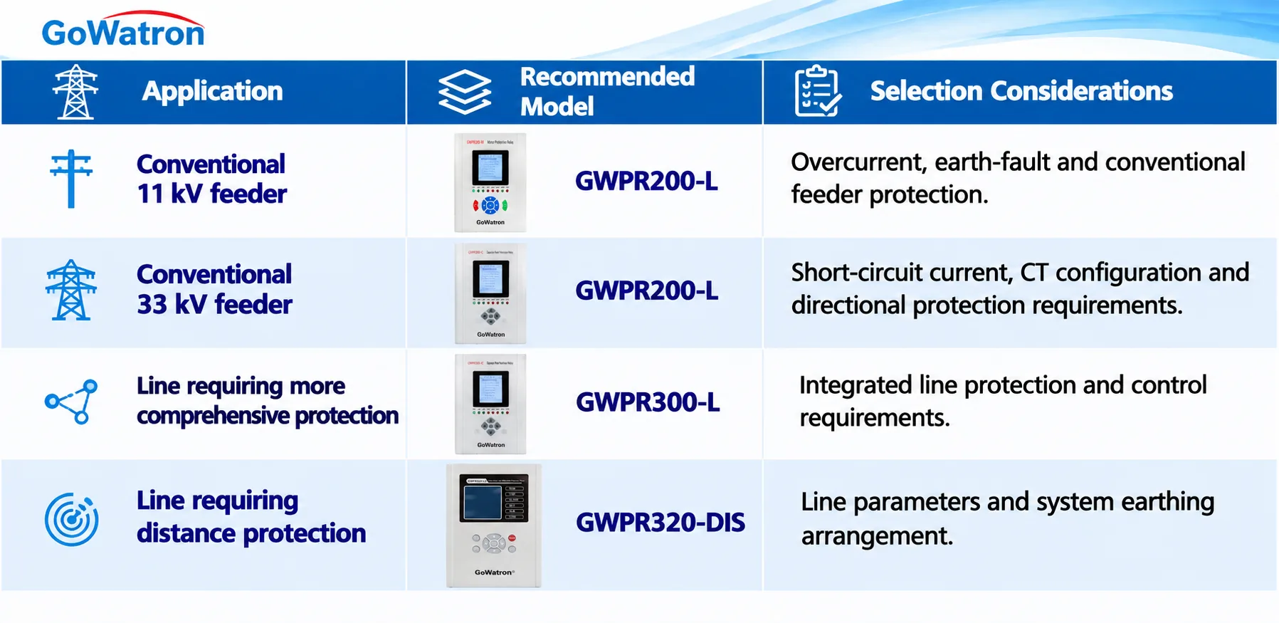
For feeders requiring only conventional overcurrent and earth-fault protection, complex differential or distance protection devices may not be necessary.
3.5 Voltage and Frequency Protection Relays
Voltage and frequency protection relays detect operating conditions in which system voltage or frequency deviates from acceptable limits.
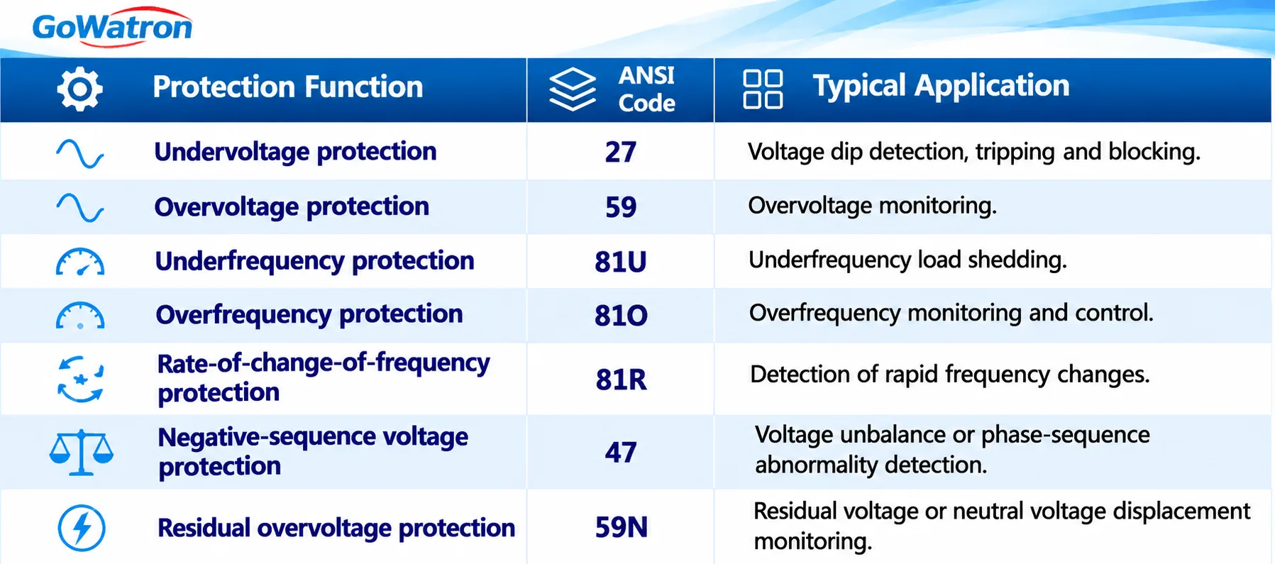
- Underfrequency load shedding (UFLS) and undervoltage load shedding (UVLS) are important measures for maintaining power system stability.
- When system frequency or voltage falls below specified thresholds, load-shedding devices can disconnect selected loads according to predefined stages and time delays to support system recovery.
- Load-shedding schemes must account for system inertia, load characteristics, frequency recovery requirements, measurement reliability and coordination with other automatic control systems.
Recommended GoWatron GWPR Voltage and Frequency Protection Relays
GWPR400-FV Underfrequency and Undervoltage Load Shedding Relay
- The GWPR400-FV provides underfrequency protection (81U), undervoltage protection (27), staged load shedding, rate-of-change-of-frequency measurement and rate-of-change-of-voltage acceleration logic.
- It is suitable for substations and industrial distribution systems requiring automatic load-shedding functions.
- The relay supports eight underfrequency load-shedding stages and eight undervoltage load-shedding stages, together with configurable voltage and frequency monitoring and load-shedding logic.
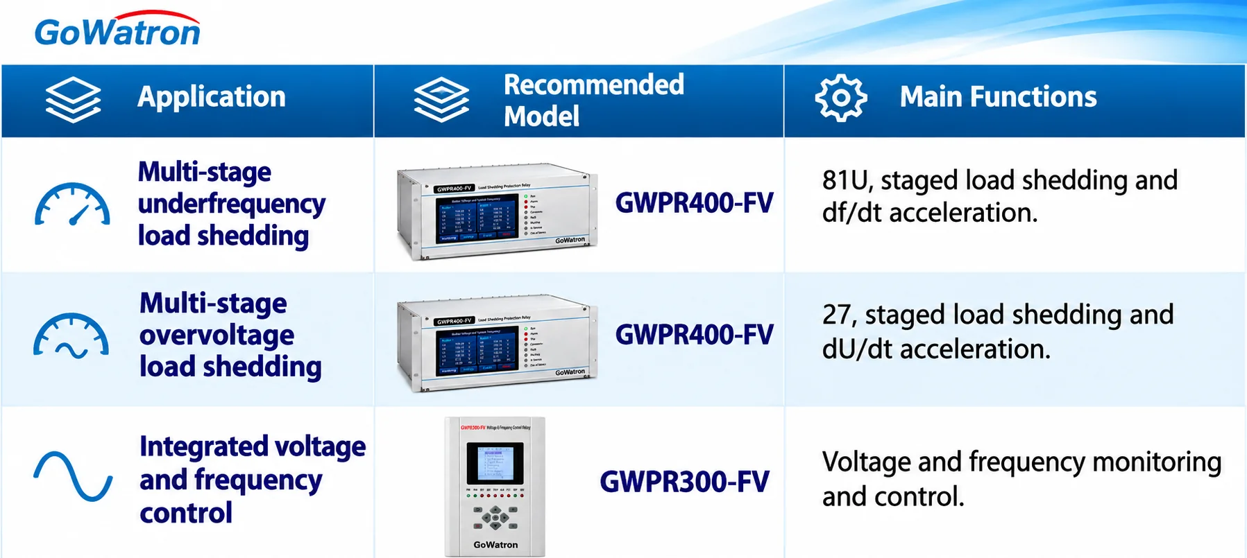
The GWPR300-FV may also be considered for suitable voltage and frequency control applications and remote load-shedding command execution.
The exact functions and communication configuration should be verified against the selected ordering option.
3.6 Capacitor Bank Protection Relays
Shunt capacitor banks are widely used in substations for reactive power compensation and voltage regulation.
Common protection functions include:
- Overcurrent protection (50/51).
- Overvoltage protection (59).
- Undervoltage protection (27).
- Capacitor bank unbalance protection (60N/60P).
- Earth-fault protection, according to the capacitor bank connection and earthing arrangement.
Capacitor bank protection must account for internal capacitor element faults, unbalance current or voltage, switching transients and harmonic effects.
The unbalance protection measurement method and settings depend on the capacitor bank connection, internal fuse arrangement and capacitor unit construction.
A single universal unbalance protection setting cannot be applied to all capacitor bank configurations.
Recommended GoWatron GWPR Capacitor Bank Protection Relay
GWPR300-C Capacitor Bank Protection Relay
- The GWPR300-C is intended for capacitor bank applications requiring unbalance protection (60N/60P), voltage protection and associated fault protection functions.
- Selection should be based on the actual capacitor bank arrangement, such as single-star, double-star or other configurations.
- The required unbalance current or voltage measurement inputs and corresponding protection functions must be confirmed for the selected configuration.
3.7 Other Substation Protection and Control Devices
In addition to the main protection categories, substations may require other specialised protection and control devices.
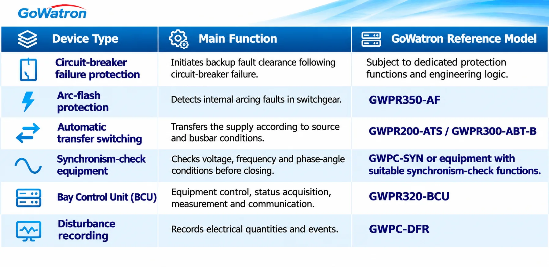 Protection devices and control devices must be distinguished.
- For example, the GWPR320-BCU primarily performs bay-level measurement, control and automation integration. The presence of programmable logic does not mean that it can replace a dedicated main protection relay.
- The GWPR350-AF can be considered for applications requiring rapid detection of internal arcing faults in switchgear.
- The specific optical sensor configuration and current-based operating criteria must be confirmed against the product documentation.


