What Are the Differences Between 87L, 87G, 87T, 87M and 87B Differential Protection Relays? A Comparison of Protected Equipment, Operating Principles and Key Setting Considerations
- In power system protection, ANSI device number 87 denotes differential protection. The designations 87L, 87G, 87T, 87M and 87B are commonly used for line differential protection, generator differential protection, transformer differential protection, motor differential protection and busbar differential protection, respectively. The precise meaning of each suffix and the scope of the associated function should be confirmed against the project documentation and the manufacturer’s technical manual.
- These five types of protection share the same fundamental concept: comparing currents at the boundaries of a protection zone after applying the necessary magnitude compensation, phase compensation and time alignment.
- A common operating principle leads to different protection configurations and setting requirements. Protection communications, transformer excitation, motor starting, current transformer transient performance and busbar arrangements all influence differential protection design and application.
1. Common Principle: Comparing Currents at the Protection Zone Boundaries
The boundaries of a differential protection zone are generally defined by the locations of the current transformers (CTs).
Taking currents flowing into the protection zone as positive, the differential current after the necessary compensation can be expressed conceptually as:
\[ I_{\mathrm{diff}}=\left|\sum_{k=1}^{n}\underline I_k\right| \]
where:
- \(I_{\mathrm{diff}}\) is the differential current;
- \(\underline I_k\) is the current phasor at each protection zone boundary, referred to a common base, reference direction and comparison instant;
- \(n\) is the number of measuring terminals included in the current comparison for that zone.
During normal operation or an external fault, the boundary currents should approximately balance. During an internal fault, current entering the protection zone is not fully balanced by current leaving through the other boundaries, producing fault-related differential current.
In practice, differential current under non-fault conditions is not always zero. CT errors, CT saturation, line charging current, transformer excitation current, and sampling or communication errors can all affect the current balance.
Differential protection therefore uses pickup thresholds, percentage restraint, compensation and supplementary criteria to provide both sensitivity to internal faults and stability during external faults.
The equation above illustrates the common principle. Individual relays may implement differential protection using sampled values, incremental quantities or other algorithms.
2. 87L Line Differential Protection: Communications, Time Alignment and Charging Current
2.1 Protection Communications Enable Current Comparison
87L line differential protection is applied to overhead lines and cable circuits. Its protection zone is generally defined by the CT locations at the two or more line terminals.
Because the terminals are usually geographically separated, the relays must exchange the current data required for protection and align those data to a common comparison instant.
Communication conditions directly affect protection performance. Application checks should cover:
- Channel delay and delay variation;
- Asymmetry between the two transmission directions;
- Data loss, communication errors and channel failure;
- The relay’s synchronisation and delay compensation methods;
- Blocking, alarm and backup protection arrangements during communication failures.
Dedicated optical fibre is a common communication medium. Communication redundancy, however, depends on the relay interfaces, communication topology, route diversity and the failure modes being considered.
Some relays support dual channels or multi-terminal ring communication arrangements that can reorganise data exchange following certain connection failures. The changeover method and recovery time are specific to the relay model and configuration and should be confirmed in the relevant technical manual.
2.2 Charging Current Produces Non-Fault Differential Current
- Line-to-earth and phase-to-phase capacitances draw charging current. These are physical shunt currents, so the sum of the terminal currents may be non-zero even when there is no internal fault.
- Charging current can affect differential protection sensitivity, particularly on long overhead lines and cable circuits.
- Relays with charging current compensation can use voltage measurements and line parameters to estimate and compensate for its effect. Where compensation is not used, charging current must be considered when determining the protection settings. The available function and its required inputs should be checked against the relay manual.
2.3 Setting and Configuration Considerations
- 87L line differential protection also requires consideration of CT ratios, polarity and transient performance at each terminal, together with operating and tripping logic for multi-terminal lines, weak-infeed terminals and terminals with no local infeed.
- The central requirement of 87L line differential protection is reliable, time-aligned comparison of currents measured at geographically separated locations.
3. 87G Generator Differential Protection: Fast Internal Fault Clearance and Defined Coverage
3.1 Main Application
- Conventional 87G generator longitudinal differential protection compares the phase currents measured at the generator terminal end and neutral end. It primarily detects stator phase-to-phase faults within the zone defined by the CTs. Whether generator connections are included depends on the actual CT locations.
- Internal generator short circuits can damage the windings, stator core and other components. The protection is therefore normally designed to operate rapidly, without unnecessary intentional delay.
- “No intentional delay” still involves a finite operating time. Total fault clearance time includes relay measurement and processing, operation of the trip output circuit, and circuit-breaker interruption.
3.2 Stator Earth-Fault Coverage
- For a generator with high-resistance neutral earthing, stator earth-fault (ground-fault) current may be small. Faults near the neutral point are particularly likely to fall outside the sensitive coverage of conventional phase differential protection.
- Dedicated stator earth-fault protection should therefore be selected according to the neutral earthing arrangement and the required coverage. Reducing the pickup setting of 87G generator differential protection alone is generally insufficient to ensure earth-fault coverage of the entire stator winding.
3.3 Interturn Fault Coverage
- An interturn short circuit within one phase winding may primarily produce a local circulating current, while the currents measured at the terminal and neutral ends remain approximately equal.
- Conventional longitudinal differential protection may therefore be insensitive to such faults at an early stage. Depending on the winding arrangement and available connections, dedicated schemes may include transverse differential protection, such as split-phase differential protection, or other interturn fault detection methods.
3.4 CT Transient Performance and Protection Stability
- Generator fault currents may contain a slowly decaying DC component, increasing the risk of transient CT saturation. External-fault stability should therefore be assessed using the fault current, DC time constant, CT excitation characteristics, remanence and secondary burden.
- Some machine differential protection functions use DC component detection, external-fault detection or CT saturation criteria as part of their blocking or other stabilising logic. The specific implementation should be assessed using the relay manual.
- The focus of 87G generator differential protection is rapid clearance of internal short circuits, coordinated with dedicated earth-fault and interturn protection to provide comprehensive stator protection.
4. 87T Transformer Differential Protection: Magnetising Inrush and Current Compensation
4.1 Why Does Magnetising Inrush Produce Differential Current?
- Transformer energisation, sympathetic inrush, or voltage recovery after clearance of an external fault can drive the transformer core into deep saturation and produce a large transient magnetising current.
- Magnetising current does not follow the normal load-current transfer relationship between the transformer windings and therefore appears as differential current. 87T transformer differential protection must distinguish this non-fault current from internal fault current while retaining fast operation for internal faults.
4.2 Second-Harmonic Blocking and Second-Harmonic Restraint
Magnetising inrush often contains a second-harmonic component that can help identify the inrush condition. Common implementations include second-harmonic blocking and second-harmonic restraint.
- Second-harmonic blocking Blocks the relevant differential element when the harmonic criterion is satisfied
- Second-harmonic restraint Incorporates a harmonic-related quantity into the restraint calculation, increasing the differential current required for operation
4.3 Ratio, Vector Group and Zero-Sequence Compensation
- Current magnitude compensation between windings;
- Phase compensation for the transformer vector group;
- Appropriate treatment of zero-sequence current components for the winding connections and earthing arrangements.
Normal starting current is principally through current, rather than differential current of the same magnitude. Machine differential protection compares the currents measured at the protection zone boundaries.
The main causes of significant non-fault spill current during starting include:
– Differences in CT errors and transient performance;
– CT saturation caused by the DC component;
– Differences in CT remanence and secondary burden;
– Incorrect CT ratios, polarity or connections;
– Incorrect protection zone configuration for special starting arrangements.
5. 87M Motor Differential Protection: Stability During Starting Transients
5.1 How Is Starting Current Related to Differential Current?
A large motor may draw a high starting current. In a correctly configured longitudinal differential scheme, however, the current entering each phase winding also leaves through the other end. With correct CT polarity and ratio compensation, the measured currents at the two ends should approximately balance.
5.2 Percentage Restraint and CT Performance Must Be Assessed Together
- For 87M motor differential protection using percentage restraint, the high through current during starting increases the restraint quantity and helps maintain stability.
- Severe CT saturation can nevertheless produce substantial false differential current. Starting stability must therefore be assessed using the restraint characteristic, CT selection and secondary circuit conditions together.
- Motor differential protection may also use a self-balancing arrangement with one window-type CT per phase. The incoming and outgoing conductors of the same phase winding pass through the CT in an arrangement that causes their magnetic effects to cancel during normal operation. An imbalance between these currents produces a CT output for the associated differential element.
- This arrangement differs from residual earth-fault current measurement using a single CT surrounding all phase conductors. CT configuration, conductor routing and setting methods must be assessed for the particular scheme. High-impedance motor differential schemes are another possible implementation.
5.3 Settings and Protection Coverage
The pickup setting of 87M motor differential protection should be determined from non-fault spill current and the required internal-fault sensitivity. A high starting current alone does not normally require the differential pickup to be set above the maximum starting current.
The main application checks are:
- Maximum non-fault spill current during starting;
- Stability during external faults;
- Sensitivity to the minimum internal fault;
- The application conditions of the high-set differential element and associated blocking logic.
Conventional motor longitudinal differential protection primarily detects phase-to-phase short circuits within its protection zone. Earth-fault detection depends on the earthing arrangement and available fault current. Its ability to detect small interturn faults should be assessed against the winding arrangement and any dedicated protection scheme.
Internal motor short circuits require rapid clearance to limit equipment damage and production disruption.
The focus of 87M motor differential protection is stability during starting transients, combined with adequate sensitivity and speed for internal short circuits.
6. 87B Busbar Differential Protection: External-Fault Stability and Zone Selection
6.1 Why Is CT Saturation During an External Fault Critical?
- A busbar is a node at which currents from multiple circuits are collected and distributed. During normal operation or an external fault, the sum of the currents at the protection zone boundaries should approximately equal zero.
- When an outgoing circuit develops an external short circuit, several source circuits may feed the fault through that circuit. Its CT may consequently carry a large through-fault current. This current may reach several times the CT rated primary current or more, depending on the system short-circuit level and CT ratio.
- Whether the CT saturates also depends on the DC component of the fault current, remanence, excitation characteristics and secondary burden. Primary current magnitude alone is insufficient to determine saturation.
- If the CT saturates, its secondary output no longer accurately reproduces the primary current, potentially creating substantial false differential current. 87B busbar differential protection must therefore remain stable under high through-fault currents and transient CT distortion.
6.2 High-Impedance Busbar Differential Protection
- In a typical current-operated high-impedance scheme, the CT secondary windings for each phase are connected in parallel with the specified polarity. The relay measuring element and stabilising resistor are connected in series, forming a high-impedance measuring branch across the parallel CT circuit.
- During an external fault with one CT saturated, the high-impedance measuring branch limits current through the relay. A substantial proportion of the resulting spill current flows through the saturated CT branch, maintaining protection stability.
- During an internal fault, the differential current drives the measuring branch to its operating threshold.
The main engineering checks include:
- CT ratios and excitation characteristics;
- CT knee-point voltage and excitation current;
- CT winding resistance and secondary lead resistance;
- Stabilising resistor resistance and thermal rating;
- Secondary overvoltage during internal faults and the required voltage-limiting measures.
The suitability of a high-impedance scheme depends on the CTs and secondary circuits as a complete system. External-fault stability, internal-fault sensitivity and secondary circuit insulation requirements must all be satisfied.
6.3 Low-Impedance Busbar Differential Protection
- Low-impedance busbar differential protection measures each circuit current separately and uses digital algorithms to calculate differential and restraint currents.
- During an external fault, the high through-fault current produces a large restraint quantity, helping the protection tolerate CT errors. To address severe CT saturation, a relay may also use external-fault detection, CT saturation detection, directional comparison or adaptive logic.
- During an internal fault, both differential and restraint currents may be large. Operation depends on their relationship and the supplementary criteria used by the relay.
- Selection between high-impedance and low-impedance schemes should consider the primary arrangement, CT characteristics and future extension requirements.
6.4 Zone Selection and Disconnector Positions
- In double-busbar and other arrangements requiring dynamic zone selection, the relay uses disconnector position indications and other relevant information to assign circuit currents to the appropriate busbar protection zones.
- Fixed-zone single-busbar schemes, and some breaker-and-a-half arrangements, may have relatively fixed measurement boundaries. Dependence on position indications should therefore be determined from the actual primary arrangement and zone configuration.
- For schemes using dynamic zone selection, position indication supervision, contact transitions during switching, and the response to abnormal indications are important commissioning and maintenance considerations.
6.5 The Role and Limitations of the Check Zone
- A check zone generally sums currents at the boundaries of an overall protection zone whose definition is independent of the busbar-selector disconnector positions. It provides an additional check on the operation of the discriminating zones, reducing the risk of unwanted tripping caused by incorrect current allocation. Its configuration and trip-permission logic depend on the protection scheme.
- The check zone and discriminating zones may share the same CT measurements. CT circuit abnormalities can therefore affect both. A complete busbar differential protection scheme also requires appropriate CT circuit supervision, CT saturation security measures and position indication supervision.
The focus of 87B busbar differential protection is correct zone definition and selective, stable operation under high through-fault currents and transient CT errors.
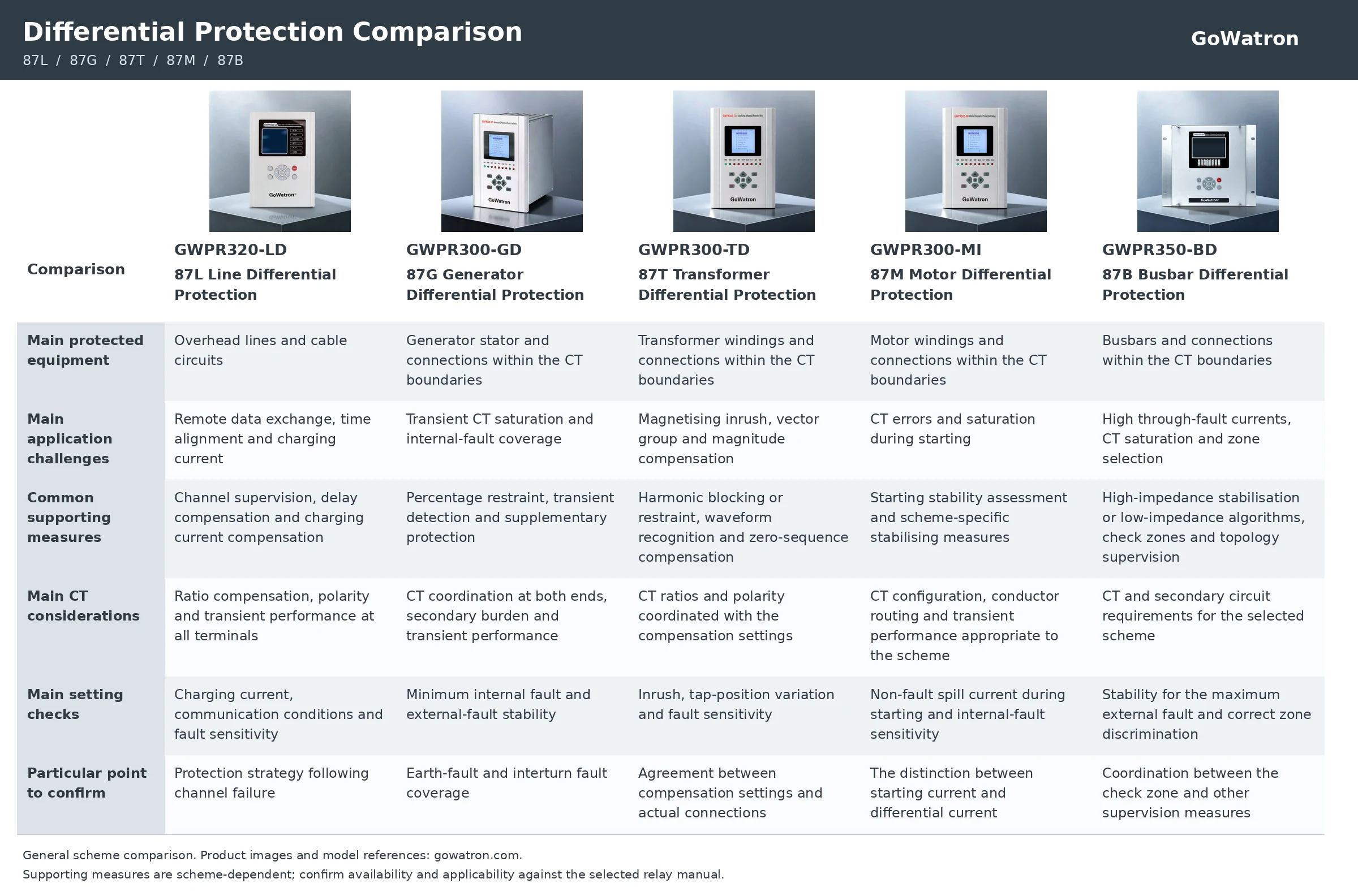
The table identifies common engineering considerations. Actual functions depend on the relay model and protection scheme. CT saturation, wiring errors and measurement errors are also shared concerns across several types of differential protection.
8. Selection and Settings: From Function Designation to Engineering Verification
The designations 87L, 87G, 87T, 87M and 87B primarily identify the protection application. Relays carrying the same designation may use different algorithms, input arrangements and supplementary logic. Conversely, a single digital relay may incorporate differential protection functions for more than one application.
The following points should be confirmed during engineering:
- Protection boundaries: Where are the CTs installed, and which equipment and connections lie within the protection zone?
- Implementation: Does the scheme use percentage restraint, high impedance, a self-balancing arrangement or another differential protection implementation?
- Measurement and compensation: How are CT ratios, polarity, phase displacement, zero-sequence components and time alignment handled?
- Non-fault stability: What differential or spill current can arise during starting, inrush, charging conditions or external faults?
- Internal-fault sensitivity: Can the minimum internal fault be detected reliably, and is supplementary earth-fault or interturn protection required?
- Abnormal-condition response: How does the protection respond to communication failures, CT circuit abnormalities or incorrect position indications?
- Tripping scope: Which circuit-breakers must trip, and which associated equipment must receive coordinated commands?
- Verification and commissioning: Have compensation settings, polarity, CT ratios, time alignment and blocking logic been verified using appropriate secondary injection, end-to-end testing, on-load checks or fault simulation?
The five types of differential protection share a common principle, while their application priorities are determined by the protected equipment. Reliable protection requires the function designation to be considered together with the primary arrangement, CT characteristics, equipment behaviour, relay algorithms and commissioning results.


