Generator Differential Protection: Working Principle, Function, and Setpoint Calculation
Document Type: Technical Articles
Document Published: 2026-08-16
Last Updated: 2026-08-17
1. Principle of Operation
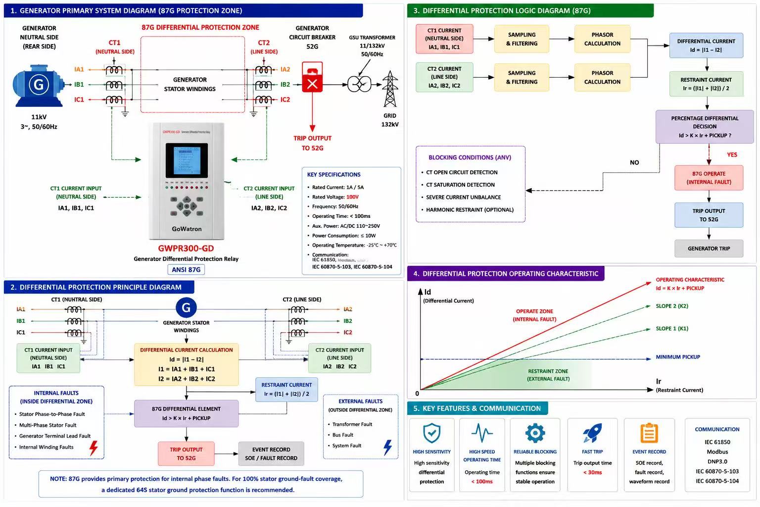
- Current transformers (CTs) of identical type and ratio are installed at both the generator terminal side and neutral side, measuring three-phase currents IT(terminal side) and IN(neutral side), with positive direction of the terminal-side CT defined toward the generator, and that of the neutral-side CT defined away from the generator (i.e., toward the system), such that the two secondary currents oppose each other under normal load conditions.
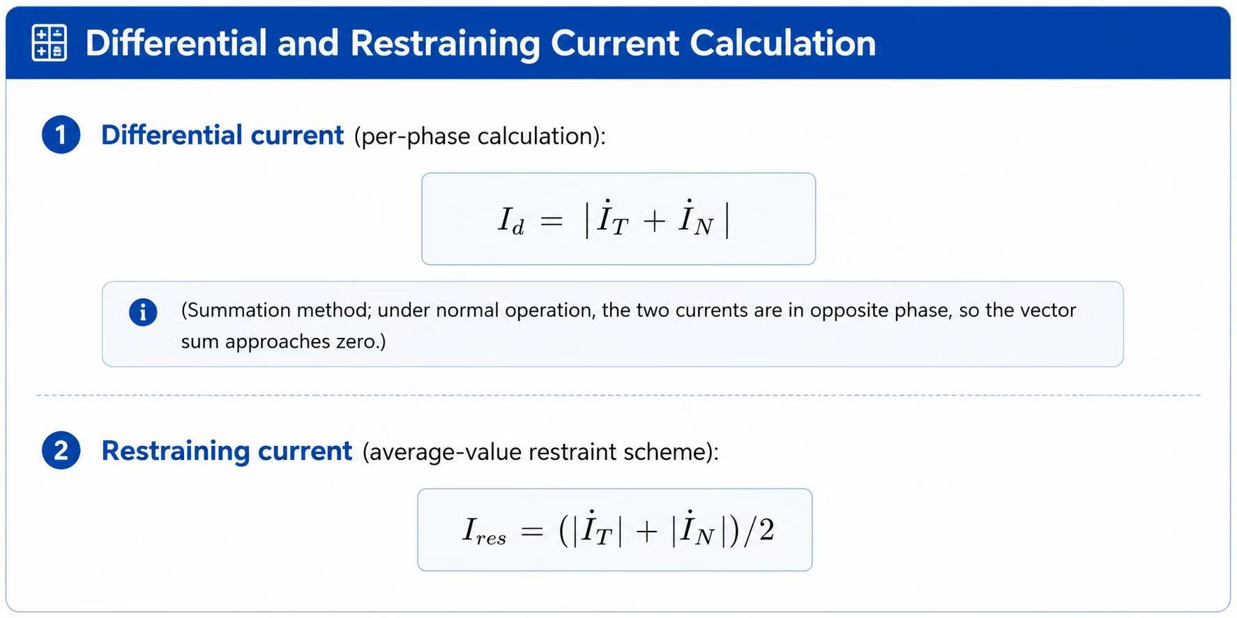
Operating logic:
- Under normal operation and external faults: the two currents oppose each other; the differential current ideally approaches zero, with only a small unbalance current due to CT errors and transient effects — the protection relay does not operate.
- For stator winding phase-to-phase faults (two-phase or three-phase): fault current is fed from the fault point, the differential current increases sharply, and the protection relay trips instantaneously when the operating point crosses the ratio-restraint characteristic.
- The ratio-restraint characteristic is designed to prevent maloperation caused by transient unbalance currents during external faults due to CT saturation.
Schematic diagram of generator differential protection.
Limitations:
- This protection relay does not respond to inter-turn short circuits within the same phase or single-phase-to-earth faults on the stator winding. These require separate protection functions (e.g., inter-turn protection relay, stator earth-fault protection relay).
2. Protection Scope and Function
- Protection type; Main protection for generator stator winding phase-to-phase short circuits
- Protected zone; Stator winding between terminal-side CTs and neutral-side CTs
- Fault types covered; Two-phase short circuits, three-phase short circuits (including those with small fault resistance)
- Output command; Instantaneous trip of the generator circuit breaker (GCB), simultaneously trip the field breaker, and initiate fault recorder
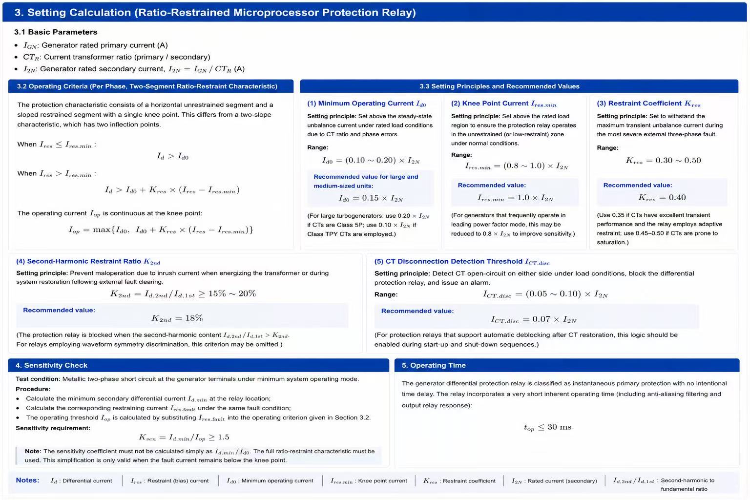
6. Key Engineering Considerations
CT Polarity and Connections
- The secondary windings of both CTs must be connected according to the polarity markings specified by the differential protection relay manufacturer, so that the theoretical differential current approaches zero under normal load and external fault conditions. Do not simply assume that “both polarities must be consistent” — always verify against the relay’s terminal block designations.
CT Selection and Matching
- Both CTs should be of identical type, ratio, and accuracy class (Class TPY or 5P20 recommended), with matched transient characteristics to minimize unbalance current during external faults.
CT Disconnection Blocking
- CT open-circuit detection should be enabled during normal operation, issuing an alarm and blocking the differential protection relay. However, during generator start-up, synchronizing, and shut-down, the blocking function should be used with caution to avoid protection blocking due to false open-circuit detections.
Second-Harmonic Restraint
- Inrush current may occur during transformer energization or post-fault voltage recovery. Second-harmonic blocking (or waveform symmetry discrimination) should be enabled to prevent nuisance tripping.
- Complementary Protection Functions
- As this differential protection relay covers only phase-to-phase faults, the following must be separately provided:
- Stator inter-turn fault protection relay (e.g., split-phase transverse differential relay, negative-sequence directional relay);
- Stator earth-fault protection relay (100% coverage using fundamental zero-sequence voltage + third-harmonic voltage scheme);
- Backup protection relays: overexcitation, overload, loss-of-field, loss-of-synchronism, etc.
On-Site Fine-Tuning
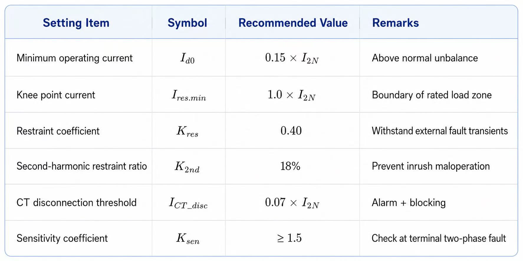
- The above recommended values are typical reference settings. Final settings should be adjusted based on generator short-circuit test data, CT saturation characteristics, and measured unbalance currents from the relay, and formally issued as a protection setting schedule.
7. Setting Summary Table (Example, Secondary Amperes)
- References: This specification complies with IEC 60050-448 (International Electrotechnical Vocabulary – Power System Protection) , IEEE Std C37.102 (Guide for AC Generator Protection Relays) , and IEC 60255 (Measuring Relays and Protection Equipment) series standards.


