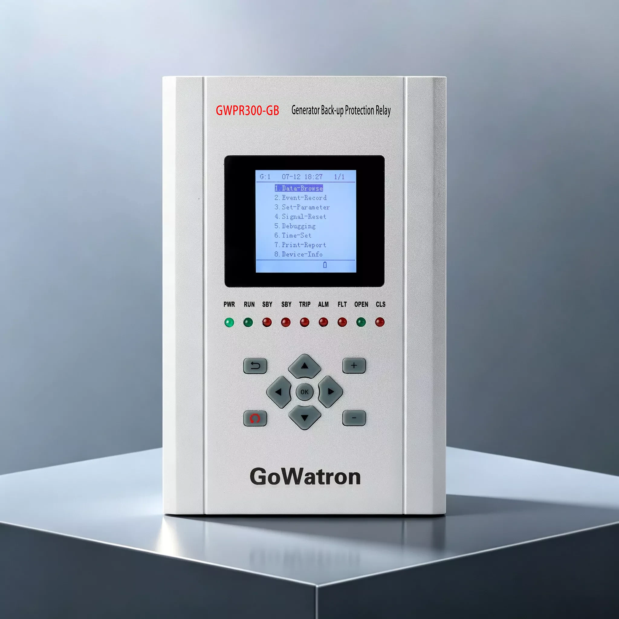
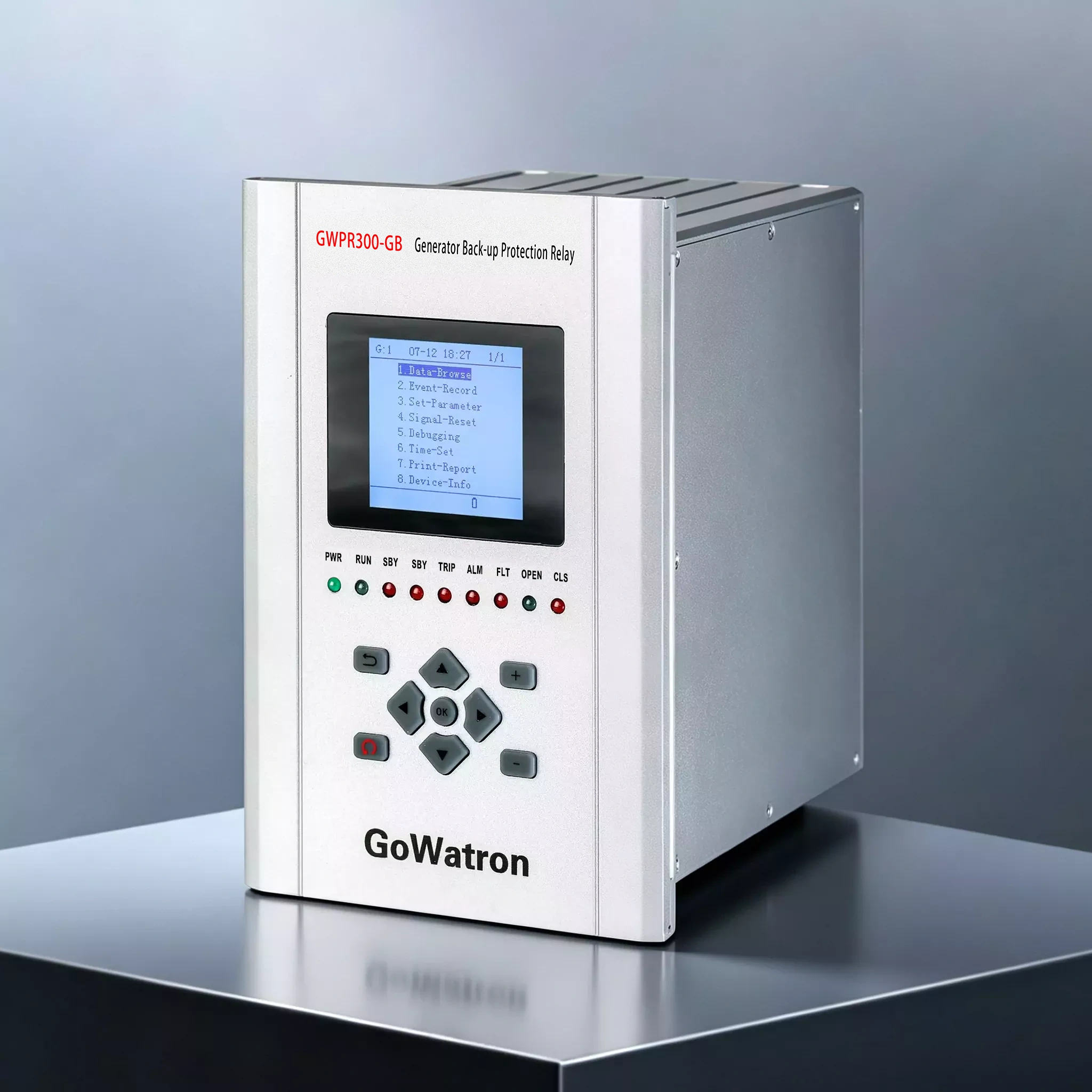
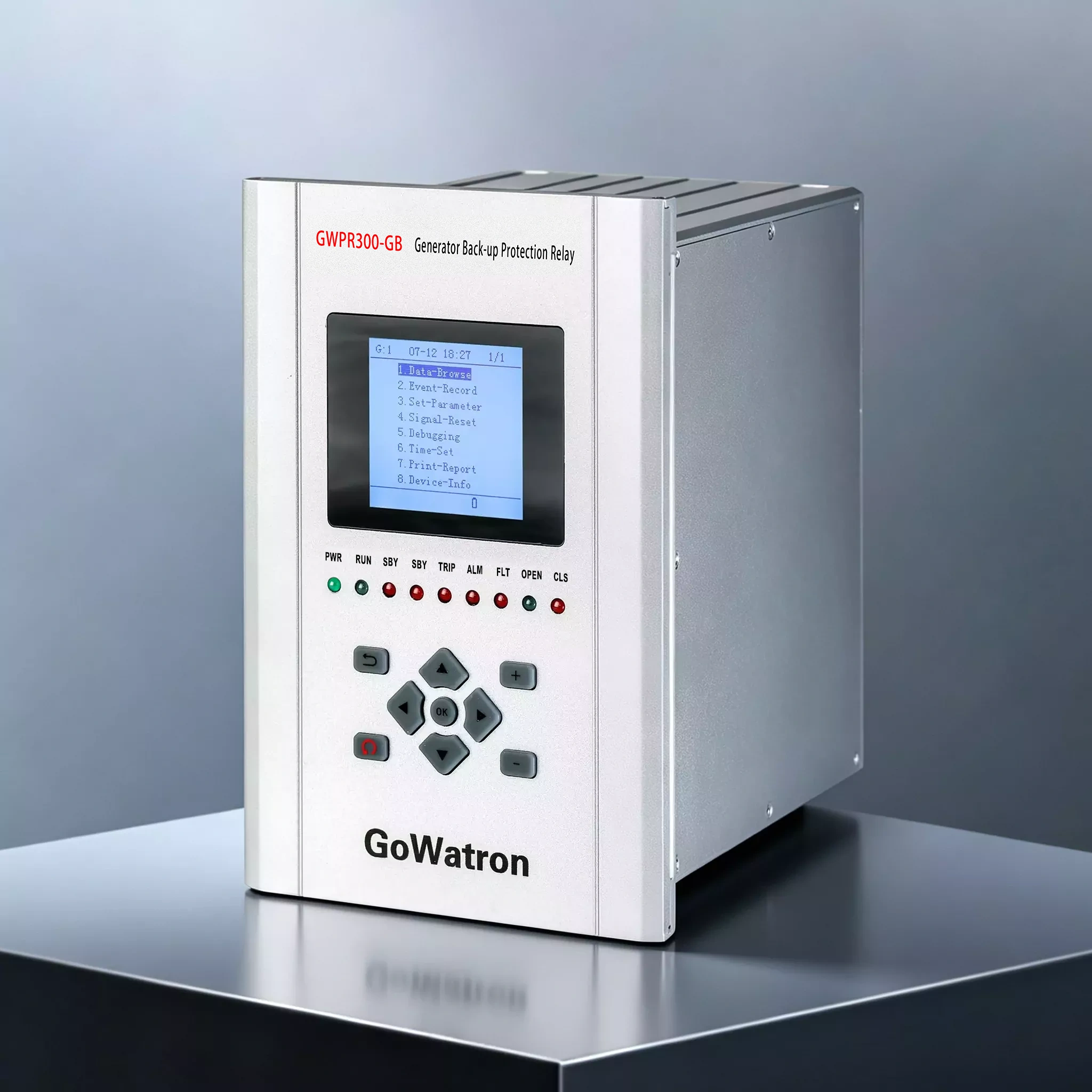
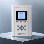
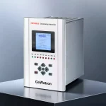
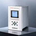
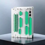
GWPR300-GB Generator Backup Protection Relay
Product Desc
The GWPR300-GB generator backup protection relay, independently developed by GoWatron, is applicable to hydro-generators with a unit capacity of ≤10 MW, steam turbine generators with a unit capacity of ≤100 MW, as well as gas generators and large-capacity diesel generator sets.
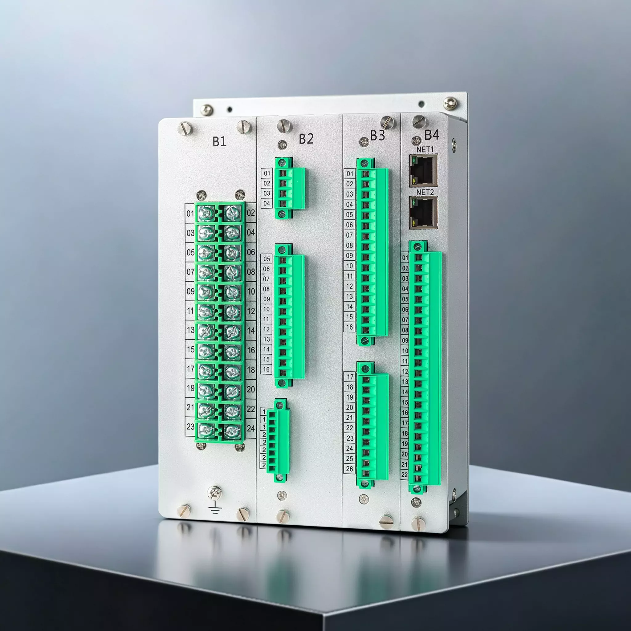
- Equipped with dual Ethernet ports and an RS485 interface, the unit is compatible with conventional substation automation systems and smart power plants.
- Standard protocols: IEC 60870-5-104 and Modbus RTU. It uploads measured values, status indications, protection operation events, alarms, fault records, and settings.
- Optional protocol: IEC 61850 (MMS and GOOSE), for integration into smart power plant networks.





Accuracy
≤ 0.2%

Quick Response
≤ 100ms

Reliable Protection
Comprehensive Protection

Quality Assurance
ISO 9001 Certified

Technical Support
24/7 Expert Support

Fast Delivery
Global Shipping

Warranty
2-Year Warranty
Product Overview
- The GWPR300-GB Generator Backup Protection Relay is a high-performance digital device. When used with the GWPR300-GD Generator Differential Protection Relay and GWPR300-GRE Generator Rotor Earth Fault Protection Relay, it forms a complete generator protection system.
- It supports both local embedded installation in switchgear and centralized panel mounting. The unit integrates comprehensive generator fault protection, high-precision electrical measurement and control, multi-channel binary status acquisition, event logging, large-capacity fault recording, multi-protocol communication, and time synchronization.
Product Functions
Protection Functions
- (ANSI 50/51V) Phase Overcurrent Protection Stage I, II, III (Tripping, blocked by undervoltage)
- (ANSI 51) Inverse Time Phase Overcurrent Protection (Tripping, with selectable Normal/Extreme/Very Inverse curves, blocked by undervoltage)
- (ANSI 49) Overload Protection (Alarm/Tripping selectable)
- (ANSI 46) Negative Sequence Overcurrent Protection Stage I (Tripping)
- (ANSI 46) Negative Sequence Overcurrent Protection Stage II (Alarm/Tripping selectable)
- (ANSI 46)Inverse Time Negative Sequence Overcurrent Protection (Tripping)
- (ANSI 50N/51N) Zero Sequence Overcurrent Protection Stage I, II (Tripping, with zero sequence voltage blocking)
- (ANSI 50N/51N) Zero Sequence Overcurrent Protection Stage III (Alarm/Tripping selectable)
- (ANSI 40) Loss of Excitation Protection (Tripping)
- (ANSI 32) Reverse Power Protection (Tripping)
- (ANSI 81O) Overfrequency Protection (Tripping)
- (ANSI 81U) Underfrequency Protection (Tripping)
- (ANSI 59) Overvoltage Protection (Tripping)
- (ANSI 27) Undervoltage Protection (Alarm/Tripping selectable)
- (ANSI 59N) Zero Sequence Overvoltage Protection (Alarm/Tripping selectable)
- (ANSI 59N) Neutral Point Zero Sequence Overvoltage Protection (Alarm/Tripping selectable)
- (ANSI 64G) Stator Ground Fault Protection (Alarm/Tripping selectable)
- (ANSI 86) System Loss of Power Protection (Alarm/Tripping selectable)
- (ANSI 60FL) PT Fuse Failure (Alarm)
- (ANSI 60) Control Circuit Fault (Alarm)
Other Functions
Measurement & Acquisition Functions
- Real-time acquisition of three-phase phase voltages, line voltages, self-generated/directly sampled zero-sequence voltages and neutral-point zero-sequence voltage; three-phase protective currents, measurement currents and zero-sequence current; active power, reactive power, power factor and system frequency; forward/reverse active and reactive energy. It supports acquisition of 21-channel active remote status inputs, and is equipped with 13 independent passive trip outputs plus 1 power-fail alarm output.
Recording & Time-stamping Functions
- Six categories of data are stored separately: protection operations, device alarms, status changes, local/remote operations, hardware self-tests and fault records. Each category can store 32 to 128 records. The unit supports printing of settings, events and fault waveforms via the local serial port. Multiple time synchronization schemes are available, including SNTP network time synchronization, IRIG-B DC hard time synchronization, and message-based time synchronization.
Local HMI Commissioning
- The unit is fitted with an LCD operation panel, supporting complete menu navigation, parameter configuration, setting group copy and switching, trip commissioning tests, waveform viewing, and device information query. No external background software is required for on-site commissioning.
Application Scenarios
- Applicable equipment: Hydro-generators of 10 MW and below, steam turbine generator units of 100 MW and below
- Grid compatibility: Generator units, unit step-up substations and auxiliary power systems supporting all neutral grounding modes
- Installation modes: Local embedded installation within switchgear cabinets, centralized panel mounting in main control rooms
- Application sites: Hydropower plants, thermal power plants, distributed new energy power stations, enterprise self-provided power plants, industrial and mining generating sets, and digital smart power plants (IEC 61850 module optional)


