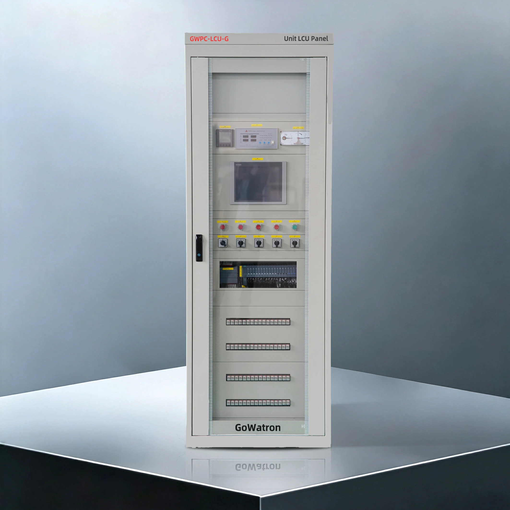
GWPC-LCU-G Unit LCU Panel
- Turbine and Generator Equipment;Hydraulic turbine-generator sets, reversible pump-turbine units for pumped-storage plants (generating and condensing modes), small steam turbine-generators and tidal turbine-generators. Unit capacities range from several hundred kW small units up to large hydro-generators with a capacity of millions of kilowatts.
- Signal Acquisition Targets;Generator electrical quantities collected via Current Transformer (CT) and Potential Transformer (PT), unit PT100 temperature signals, pressure, flow rate, rotating speed, liquid level, protection trip contacts, position switches and 4–20mA analog transducer signals.
- System Compatibility;Compatible with plant-level host computers, Remote Terminal Unit (RTU), dispatching systems, protection devices, fault recorders and electrical energy metering equipment. It supports mainstream power communication protocols including IEC 61850, Modbus TCP/RTU, serial communication and fiber-optic communication.




Major Functions
1. Full-Range Data Acquisition & Processing
Analog Quantities: Generator voltage, current, active/reactive power, frequency, power factor, bearing/stator temperature, oil pressure, water pressure and wicket gate opening;
Digital Quantities: Circuit breaker open/close status, valve positions, protection trip signals, brake status, running state of oil pumps and drainage pumps.
Temperature readings, energy data and speed pulse signals are acquired in real time, processed with digital filtering, engineering unit conversion, limit threshold judgment and real-time buffer storage.
The panel generates Sequence of Events (SOE) records to precisely log the chronological sequence of faults, with a time resolution of 1 ms.
2. Full-Automatic Unit Sequence Control
Complete sequential control logic: One-click startup → voltage build-up → transmit the “synchronization permission” signal to the synchronization panel (the panel completes voltage difference, frequency difference and phase angle difference judgment and outputs the closing command); one-click shutdown; mode switching among generating, condensing and pumping modes for pumped-storage units.
Three hierarchical operation modes: Remote automatic control via central control room, local automatic control via touchscreen, and step-by-step local manual operation.
Safety interlock logic: The system checks all interlock permissive conditions prior to any operation (e.g., brake reset, fully closed wicket gate, zero rotating speed). Operations are blocked if permissive conditions are unsatisfied to avoid misoperation.
3. Power Regulation Logic Interaction
Closed-loop regulation: The panel receives active/reactive power setpoints from the dispatching center or central control room, and outputs corresponding commands to the governor for active power regulation and to the excitation system for reactive power regulation respectively.
Grid synchronization coordination: The LCU only outputs “synchronization permission” and “closing enable” logic signals. Voltage, frequency and phase angle matching are fully implemented by hardware inside independent synchronization panels, and the LCU does not participate in outputting the final circuit-breaker closing pulse.
4. Fault Monitoring, Alarm and Shutdown Protection
Real-time audible & visual alarms will be triggered for static limit violations and rate-of-change violations, displayed on the touchscreen and uploaded to the central control system.
Graded fault handling mechanism:
- General faults: Alarm signal output only, no unit operation intervention;
- Major faults (overspeed, overtemperature, low oil pressure, electrical faults): Automatic activation of PLC-logic-based fault shutdown procedures;
- Emergency trip: A hardwired trip circuit completely independent of the PLC CPU (equipped with hardware watchdog or dedicated relay logic) directly closes wicket gates and trips the generator outlet circuit breaker. The trip signal is simultaneously fed into the PLC via a digital
- input channel for event logging and fault playback.
The system supports local storage of fault records, historical trend curves and playback records to facilitate maintenance and fault diagnosis.
5. Local Human-Machine Interface (HMI) Operation
The touchscreen displays unit overview, parameter trend curves, fault logs and operation diagrams.
The front panel is equipped with selector switches, operation pushbuttons, red/yellow/green status indicator lamps, audible & visual alarm devices and an independent hardwired emergency shutdown pushbutton.
Off-line autonomous operation: If the central control system or communication network malfunctions, the LCU can independently monitor and control the generating unit. In this mode, the touchscreen holds full operation authority, while all remote dispatching control commands are automatically blocked to ensure safe unit operation.
6. Multi-Channel Communication Interaction
- Uplink: Upload real-time operating data, alarms and event logs to the central monitoring system, RTU and dispatching master station;
- Downlink: Receive remote start/stop, power regulation and mode-switching commands from the dispatching side;
- Peer-to-peer horizontal communication: Bidirectional data exchange with speed governors, excitation systems, protection devices, common-unit LCUs and independent synchronization panels.
The panel adopts dual redundant communication networks integrated with communication surge protection to withstand severe electromagnetic interference inside hydropower plants.
7. Hardware Self-Diagnosis & O&M Management
Online self-diagnosis functions cover PLC, I/O modules, power supplies and communication links, enabling board-level fault localization and alarm upload.
Local storage of operating trend curves, fault logs, cumulative energy statistics and operator activity logs.
Hierarchical operation access control is realized via touchscreen passwords and key-lock switches, complying with unattended or minimally attended operation standards for hydropower plants.
Unit LCU Panel Configuration (Hardware Architecture)
This specification defines the hardware configuration and structural parameters of the GWPC-LCU-G Unit LCU Panel. Standard panel dimensions: 2260 mm (H) × 800 mm (W) × 600 mm (D)
1. Core Control Unit
- PLC main controller (CPU module): Central unit for overall logic calculation and data processing;
- I/O expansion modules: Analog Input (AI), Analog Output (AO), Digital Input (DI), Digital Output (DO), PT100 temperature acquisition modules and high-speed counter modules (rotating speed measurement).
Medium and large generating units are configured with dual-PLC redundancy (Active-Standby hot redundant mode or Dual-Master with Voting mode), matched with dual redundant power supplies and dual redundant communication networks.
2. Electrical Measurement & Signal Isolation Components
Multifunction power meters and current/voltage transducers convert high-voltage strong electrical signals into standard 4–20mA weak analog signals.
Interposing relays provide galvanic isolation for low-level PLC signals and drive field solenoid valves and contactors.
Partitioned terminal blocks are deployed to separate AI/AO/DI/DO loops for convenient field wiring and commissioning.
3. Human-Machine Interface Components
- Industrial touchscreen (10-inch or 15-inch);
- Selector switches (Local/Remote, Manual/Automatic), operation pushbuttons, status indicator lamps, audible & visual alarm units, hardwired emergency shutdown pushbutton.
4. Power Supply & Surge Protection System
Dual redundant power input: AC220V + DC220V / DC110V station DC battery power supply.
Equipped with switching power supplies and backup power modules. The backup unit sustains PLC operation for a minimum of 5 seconds after power loss to preserve complete fault operation data.
Power Surge Protective Devices (SPDs) and communication SPDs are installed, with nominal discharge current of 20 kA (8/20 μs standard waveform).
5. Communication Components
Industrial Ethernet switches, fiber-optic transceivers, RS485 communication modules and multi-protocol communication management devices.
6. Panel Auxiliary Accessories
Heavy-duty steel panel, door locks, cooling fans, earthing copper busbars, equipment nameplates, internal compartment lighting and wiring trunking.
Application Scenarios
- Conventional Hydropower Plants (Core Application);Run-of-river, dam-toe and diversion hydropower plants. Each hydro-generator is equipped with an independent GWPC-LCU-G Unit LCU Panel to realize standalone automation monitoring per unit and support unattended power station operation.
- Pumped-Storage Power Plants;The LCU controls reversible pump-turbines under generating and condensing modes. Pumping mode is also managed by the same LCU via PLC logic switching. If pumping auxiliary systems (e.g., Static Frequency Converter (SFC) starting devices, high-pressure oil injection pumps) are large-scale and housed in separate panels, these auxiliary panels communicate with the main LCU as sub-stations, and the main LCU retains full master control ownership.
- Small-Scale Distributed Power Stations;Mini hydropower stations and tidal generating units can adopt a simplified version of this automation system to lower automation investment for small power plants.
- Automation Retrofit of Aging Hydropower Plants;Replaces conventional relay-based control panels to deliver digital remote monitoring and SOE fault recording, completing intelligent upgrade of legacy units.
- Auxiliary Generating Units for Energy Storage;Applicable to medium & small synchronous-motor-driven energy storage generating units (e.g., expanders for compressed air energy storage, synchronous generating units for pumped energy storage), realizing coordinated power regulation and grid-connection logic control.


