Generator Loss-of-Excitation Protection (ANSI 40): Operating Principle, Functions and Setting Calculations
1. Overview
- Generator loss-of-excitation protection, also known as loss-of-field protection (ANSI 40), detects abnormal operating conditions caused by the loss or severe reduction of excitation in a synchronous generator.
- Following a loss of excitation, the generator may absorb reactive power from the power system and lose synchronism. Depending on the generator characteristics and system conditions, this can result in increased stator current, rotor heating, reduced terminal voltage and adverse effects on system stability.
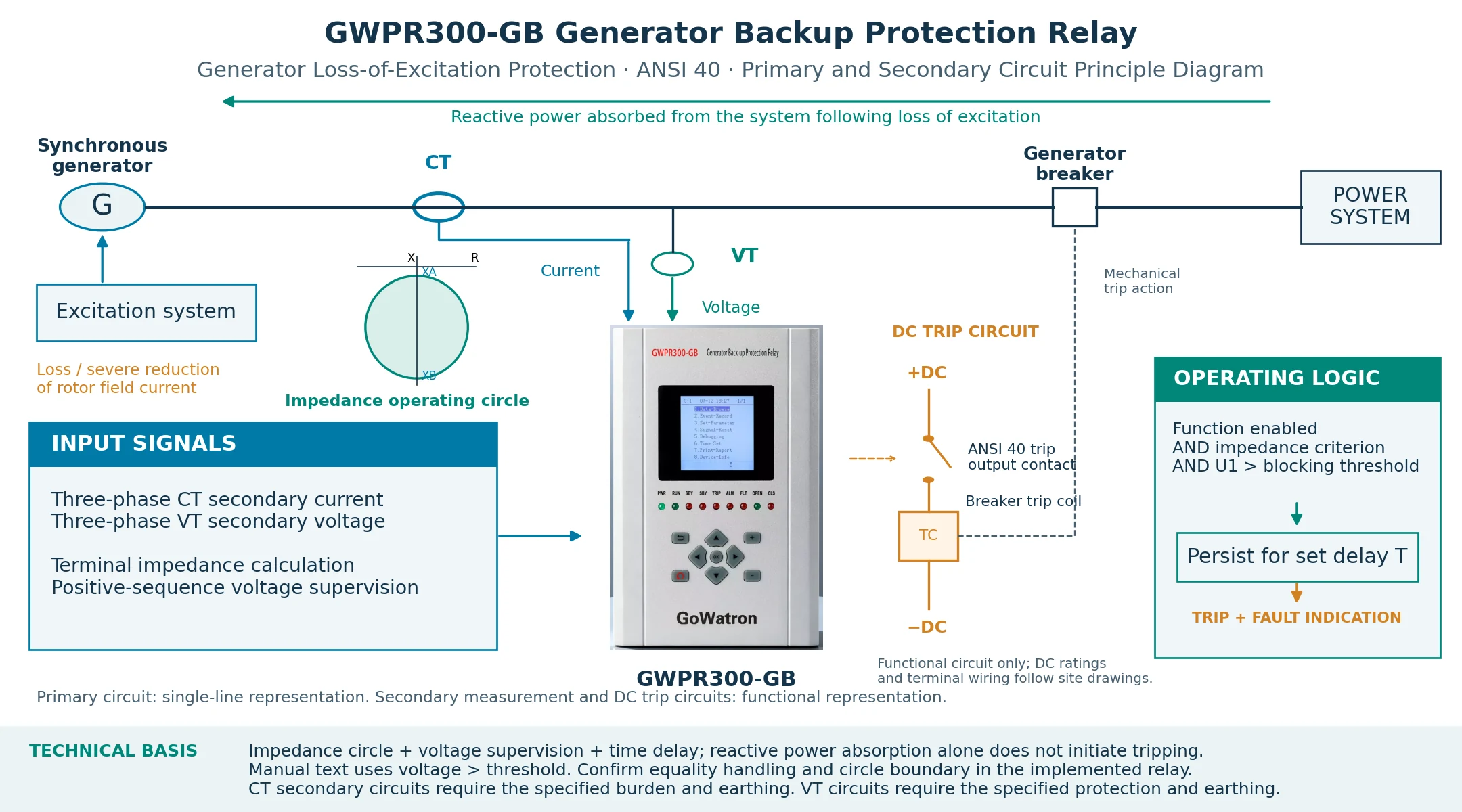
- The GoWatron GWPR300-GB Generator Backup Protection Relay uses an impedance criterion measured at the generator terminals, with positive-sequence voltage supervision and an operating time delay. When the required conditions persist for the set time, the relay issues trip signals and activates a fault indication output.
- The product-specific operating conditions and calculation formulas below are based on Section 3.11, pages 23–25, of the supplied operation manual. The setting ranges are specified on page 57.
2. Operating Principle
2.1 Generator Behaviour Following Loss of Excitation
- During normal operation, the excitation system supplies the rotor field current required for synchronous operation. The generator’s reactive power exchange with the system depends on its excitation level and operating point.
- If excitation is lost or becomes insufficient, the generator may begin absorbing more reactive power from the system. Its terminal voltage can decrease, and stator current may increase. If the generator loses synchronism, asynchronous operation and rotor slip can produce additional heating.
- These changes affect the impedance measured at the generator terminals. Loss-of-excitation protection detects the abnormal impedance trajectory and applies voltage supervision and a time delay to determine whether a trip should be issued.
2.2 Impedance Operating Characteristic
For a positive-sequence impedance calculation:
\[ Z_1=\frac{U_1}{I_1} \]
where:
- \( Z_1 \)is the positive-sequence impedance;
- \( U_1 \) is the positive-sequence phase-voltage phasor;
- \( I_1 \)is the corresponding positive-sequence current phasor.
The voltage and current phasors must use consistent phase references. The relay’s implemented impedance calculation and measurement convention must be confirmed from its technical documentation.
For the measurement direction represented by the manual’s impedance diagram, the loss-of-excitation operating circle lies in the negative-reactance half-plane of the R–X impedance plane. The R-axis is horizontal, and the X-axis is vertical, with positive reactance upwards.
The two intercepts on the reactance axis are designated \( X_A \) and\( X_B \):
\( X_A \) is the intercept closer to the origin;
\( X_B \)is the farther intercept.
For the characteristic described here:
\[ X_B<X_A<0 \]
The circle centre is:
\[ Z_c=j\frac{X_A+X_B}{2} \]
The radius is:
\[ r=\frac{|X_B-X_A|}{2} \]
Let \(Z\) denote the terminal impedance used by the protection element. The theoretical criterion for this impedance to lie strictly inside the circle is:
\[ \left|Z-j\frac{X_A+X_B}{2}\right| < \frac{|X_B-X_A|}{2} \]
This expression describes the circle geometry. Whether the relay includes the circumference in its operating region requires confirmation because the manual’s formula and written operating conditions use different boundary descriptions.
2.3 Voltage Supervision and Time Delay
According to the written operating conditions in the supplied manual, loss-of-excitation protection operates when:
- The loss-of-excitation function is enabled.
- The measured impedance satisfies the impedance operating criterion.
- The positive-sequence voltage is above the undervoltage blocking threshold.
- These conditions remain satisfied for at least the operating time delay.
Under this description, the element is blocked when the positive-sequence voltage is below the undervoltage blocking threshold. Once the voltage satisfies the condition for releasing undervoltage blocking, the element can operate if the impedance and time-delay conditions are also satisfied.
The exact comparison at the voltage threshold must be confirmed against the implemented relay logic.
3. Purpose and Protection Action
Loss-of-excitation protection helps limit generator damage and system disturbances by detecting abnormal excitation conditions and initiating generator disconnection.
Its principal purposes are to:
- Limit exposure to abnormal stator and rotor heating.
- Detect sustained operation within the loss-of-excitation impedance region.
- Reduce the effect of excessive reactive power absorption on system voltage.
- Support the generator protection scheme during loss of synchronism caused by excitation failure.
The supplied GWPR300-GB manual states that operation initiates the designated trip outputs and the fault indication output. It also describes fault information on the LCD and a fault indicator that requires manual reset.
Whether the installation initiates generator disconnection, de-excitation or a complete unit shutdown depends on the external trip wiring and the approved plant protection scheme.
Loss-of-excitation protection does not replace dedicated out-of-step protection. These functions must be coordinated according to the generator and system requirements.
4. Setting Calculations
4.1 Required Generator and Instrument Transformer Data
The calculation requires the following information:
\( U_N \) Rated generator line-to-line voltage
\( S_N \)Rated three-phase apparent power
\( x_d \) Direct-axis synchronous reactance in per unit
\( x’_d \) Direct-axis transient reactance in per unit
\( K_{CT} \)CT ratio: rated primary current divided by rated secondary current
\( K_{VT} \) VT ratio: rated primary voltage divided by rated secondary voltage
The per-unit reactances must be referred to the same voltage and power bases as \(U_N\) and \(S_N\).
The CT and VT ratios used here are dimensionless. Their rated primary and secondary quantities must be expressed in consistent units, using the voltage transformation ratio applicable to the relay’s measurement circuit.
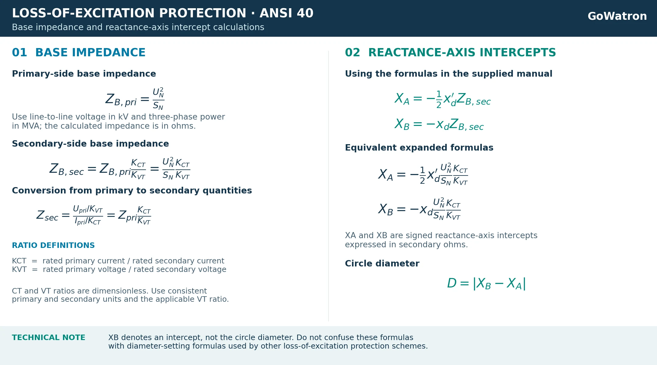
4.2 Base Impedance/Reactance-Axis Intercepts of the Impedance Circle
5. Worked Example
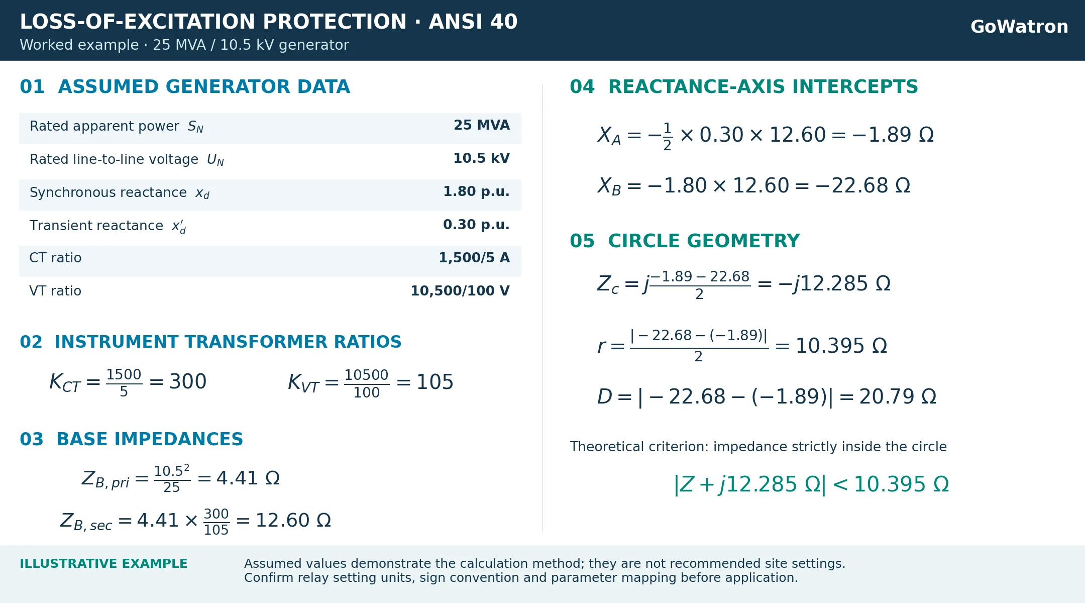
The following assumed values illustrate the calculation method. They are not recommended settings for any particular installation.
6. Operating Time Delay and Undervoltage Blocking
The supplied manual specifies the following settings:
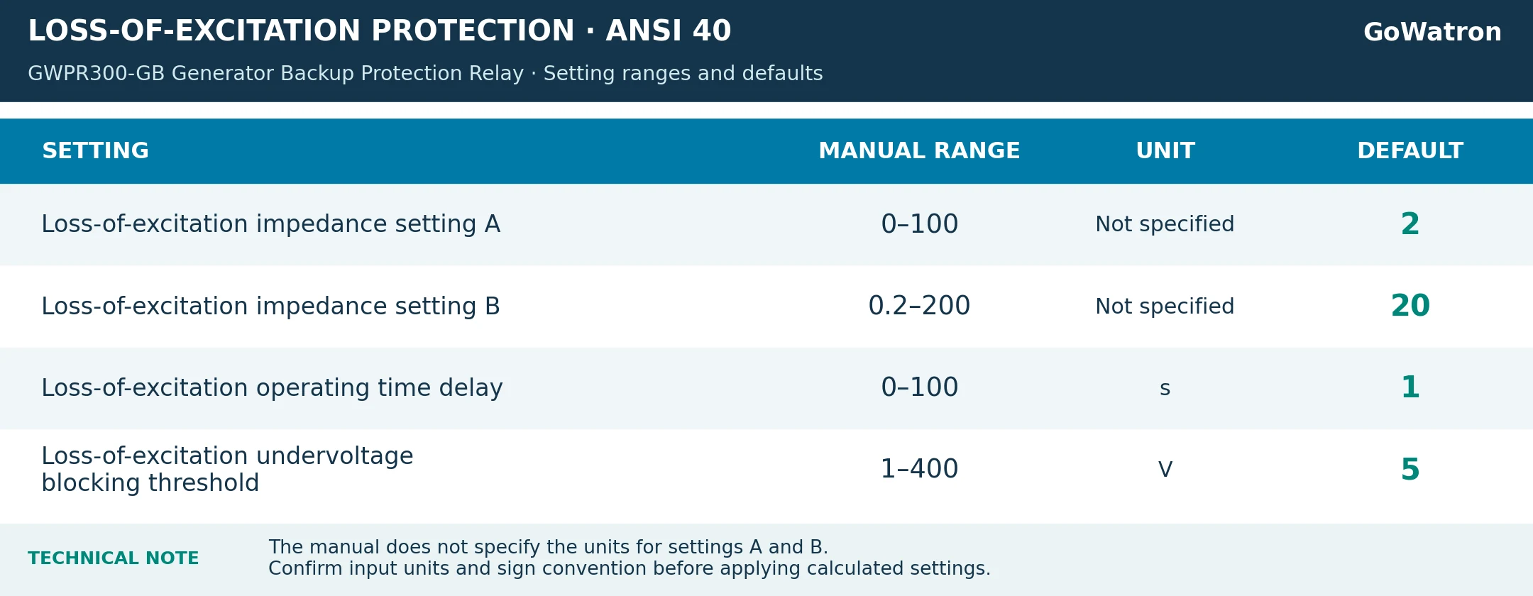
- The impedance setting units are not stated in the setting table. Although the formulas calculate secondary-side impedance, the relay’s actual input units and sign convention must be confirmed before preparing the final setting schedule.
- The operating time delay should take into account the generator’s permissible operation following loss of excitation, expected power swings, excitation system behaviour and coordination with other protection functions. It should provide security against unwanted operation
during temporary disturbances while ensuring timely operation under sustained abnormal conditions. - The undervoltage blocking threshold must be selected using the relay’s voltage measurement convention and the installation’s VT secondary ratings. The default value of 5 V is a factory setting and does not establish the appropriate threshold for every generator.
- Likewise, a threshold of 0.6–0.7 times rated voltage should not be applied without product-specific justification and a protection coordination study.
7. Setting and Coordination Considerations
- Coordination with the underexcitation limiter. The operating characteristic should be checked against the excitation regulator’s underexcitation limiter and the generator’s underexcited operating capability. Protection should remain secure within the permitted operating region.
- Coordination with other protection functions. Loss-of-excitation protection should be coordinated with out-of-step protection, undervoltage protection and other relevant generator and system protection functions.
- Consistent impedance bases. Primary impedance, secondary impedance and per-unit values must be clearly distinguished. Incorrect CT or VT ratios can substantially change the effective operating characteristic.
- Measurement polarity and current direction. CT polarity, VT phase relationships and the relay’s current direction convention must match the assumptions used for the R–X characteristic.
- Trip scheme verification. The assigned outputs, external wiring, fault indication and manual reset requirements should be checked against the approved plant drawings.
- Secondary injection testing. Commissioning should verify the impedance characteristic, voltage supervision, operating time delay, output contacts and reset behaviour. Tests should include points inside and outside the circle and points close to the impedance and voltage thresholds.
8. Conclusion
- Generator loss-of-excitation protection (ANSI 40) detects abnormal excitation conditions through changes in the impedance measured at the generator terminals.
- The GoWatron GWPR300-GB Generator Backup Protection Relay applies an impedance operating characteristic with positive-sequence voltage supervision and an operating time delay. The supplied manual calculates the reactance-axis intercepts using the generator’s transient and synchronous reactances, rated voltage, rated apparent power, and CT and VT ratios.
- Final settings must be checked against the generator capability, excitation system, protection coordination requirements and the relay’s confirmed parameter conventions.


