Generator Reverse Power Protection (ANSI 32): Working Principle, Purpose and Setting Calculations
I. Overview
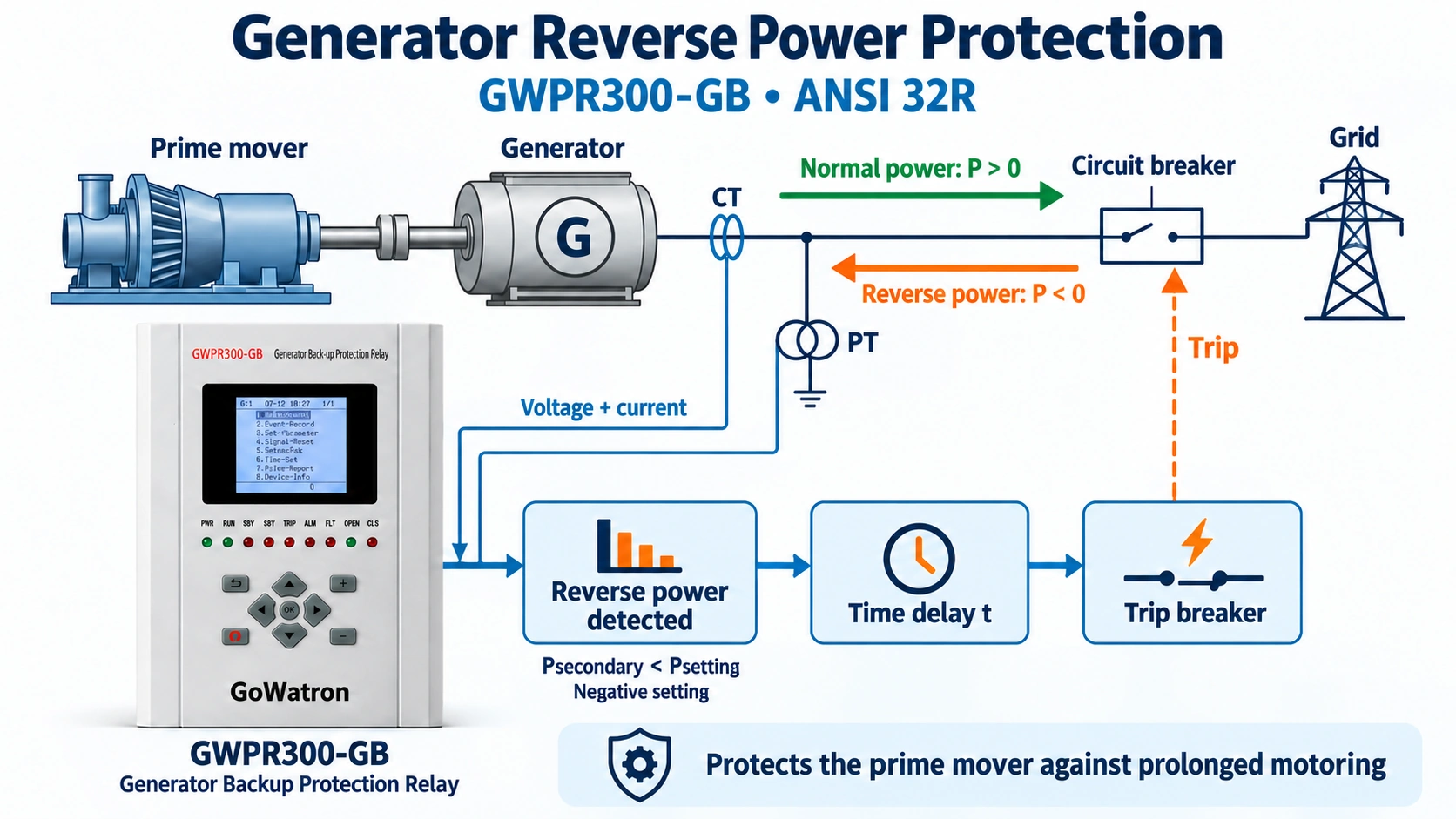
- Generator reverse power protection (ANSI 32R) detects active power flowing from the grid into the generator. This condition can occur when the prime mover loses sufficient mechanical input while the generator remains connected to the grid. The generator then operates as a synchronous motor, drawing active power from the grid and mechanically driving the prime mover.
- Reverse power protection is mainly used for steam turbine generators, gas turbine generators, hydro generators and diesel generators. Its principal purpose is to protect the prime mover against the consequences of prolonged motoring operation.
- The GWPR300-GB Generator Backup Protection Relay incorporates reverse power protection (ANSI 32R) as one of its protection
functions. It monitors active power and its direction. When the magnitude of reverse power exceeds the configured pickup threshold and persists for the specified time delay, the relay issues a trip command. - Reverse power refers to a reversal of active power flow. It does not mean that the generator or prime mover rotates backwards.
II. Working Principle
2.1 Normal and Reverse Power Flow
During normal operation, the prime mover supplies mechanical energy to the generator. The generator converts this energy into electrical energy and exports active power to the grid.
Normal power flow: Prime mover → Generator → Grid
In this article, active power exported from the generator to the grid is defined as positive:
\( P>0 \) : Normal power generation
If the steam turbine main stop valve closes, the gas turbine fuel supply is interrupted, or another condition reduces the prime mover’s mechanical input sufficiently, the generator may begin drawing active power from the grid while remaining synchronised.
Motoring power flow: Grid → Generator → Prime mover
Under the sign convention used in this article:
\( P<0 \): Reverse power operation
The generator operates as a synchronous motor and drives the connected prime mover in its normal direction of rotation.
2.2 Active Power Measurement
The protection relay receives generator voltage and current signals through voltage transformers (PTs) and current transformers (CTs). It calculates active power and determines its direction.For a balanced three-phase system with sinusoidal voltage and current:
\[ P=\sqrt{3} \times U \times I \times \cos \varphi \]
| Symbol | Description |
| P | Total three-phase active power |
| U | Line-to-line RMS voltage |
| I | Line RMS current |
| cosφ | Power factor |
- Digital protection relays calculate active power from sampled voltage and current signals. In this article, PT is used consistently for the voltage transformer, matching the terminology in the GWPR300-GB manual.
- Pset denotes the positive magnitude of the reverse power pickup setting. With generator export defined as positive, the general pickup condition is:
\[ P≤−P set \]
The equivalent condition is:
\[ P<0and∣P∣≥P set \]
- The absolute-value condition must include the reverse power direction. Otherwise, normal forward power could also satisfy it.
- The absolute-value condition must include the reverse power direction. Otherwise, normal forward power could also satisfy it.
- Some relays express the reverse power setting as a positive magnitude and use a separate direction criterion. Others use a signed power setting. The setting convention and exact comparison must follow the relay manual.
- During commissioning, confirm whether the relay’s power measurement and pickup logic use the same sign convention. A mismatch between the displayed power sign and the setting sign can cause unexpected operation.
2.3 Typical Operating Logic
The basic operating sequence is:
- Mechanical input decreases or is lost → Active power reverses → Reverse power threshold is reached → ANSI 32R picks up → Time delay expires → Alarm or trip, according to the protection scheme
- Reverse power protection normally uses a definite-time delay to ride through brief reverse power conditions associated with synchronisation, system disturbances and transient power swings.
- The GWPR300-GB applies this principle through its built-in reverse power element, which operates to trip after the configured delay. It does not provide a separate reverse power alarm stage.
III. Main Functions
3.1 Protection of the Prime Mover
- For a steam turbine generator, closure of the main stop valve or interruption of the steam supply may leave the generator connected to the grid without sufficient mechanical input.
- The generator then draws active power from the grid and mechanically drives the steam turbine. With insufficient steam flow, windage and ventilation losses can produce overheating, particularly in the exhaust stages. Prolonged motoring may damage the turbine.
- Gas turbines, hydro turbines and diesel engines have different motoring characteristics and associated mechanical, thermal or operational risks. Reverse power settings must therefore reflect the requirements of the specific prime mover.
3.2 Prevention of Prolonged Motoring
- Reverse power protection prevents the prime mover from remaining in motoring operation after its mechanical input becomes insufficient.
- It is not primarily an overload protection function. Its operation depends on the direction and magnitude of active power.
- Motoring power and permissible motoring duration vary between machine types and operating conditions. A single pickup percentage or time delay should not be applied to all generating units.
- The GWPR300-GB reverse power setting and time delay should be selected according to the prime mover manufacturer’s data, the generator operating conditions and the unit protection scheme.
3.3 Coordination with Sequential Tripping
- Turbine shutdown initiated → Main stop valve closes → Mechanical input decreases → Reverse power is confirmed → Configured delay expires → Generator circuit breaker trips
- Reverse power confirmation indicates that the generator is drawing active power from the grid before it is disconnected. In appropriate shutdown sequences, this helps reduce the risk of turbine overspeed.
- The GWPR300-GB reverse power element can be incorporated into this coordinated scheme. Sequential tripping must coordinate with turbine controls, valve status signals and circuit breaker operation, without delaying faults that require immediate electrical isolation.
IV. General Setting Calculation
| Setting | Purpose |
| Reverse power pickup setting, Pset | Determines the reverse power magnitude required for pickup |
| Reverse power time delay, t | Determines how long the pickup condition must persist before operation |
4.1 Reverse Power Pickup Setting
\[ P_{set}=K \times P_{mot} \]
| Symbol | Description |
| Pset | Positive magnitude of the reverse power pickup setting |
| Pmot | Positive magnitude of the active power absorbed from the grid during the relevant motoring condition |
| K | Setting coefficient selected according to machine characteristics and protection requirements |
A setting coefficient of approximately 0.3–0.7 may be used as an initial reference in suitable applications. A value of 0.5 is used in the calculation example below. These values are not universal settings.
The final pickup setting should be checked against:
- The minimum expected motoring power.
- The prime mover manufacturer’s requirements.
- The relay’s active power measurement performance.
- PT and CT ratio errors and phase displacement.
- The protection scheme and commissioning results.
A lower threshold increases sensitivity but places greater demands on measurement accuracy. A higher threshold may fail to detect low motoring power.
4.2 Determining Motoring Power
- Use motoring power data supplied by the prime mover manufacturer wherever available. Approved commissioning measurements may also be used to verify the setting.
- Measured values should represent stable motoring under defined test conditions. A transient peak at the instant of power reversal should not be used directly as the steady motoring power.
- Record the relevant conditions, including voltage, frequency, excitation, machine configuration and auxiliary equipment status.
| Prime mover | Main setting consideration |
| Steam turbine | Motoring power may be a small percentage of rated active power, requiring sensitive measurement |
| Gas turbine | Motoring power depends strongly on compressor loading and shaft arrangement |
| Diesel engine | Motoring power depends on engine design and mechanical losses |
| Hydro turbine | Motoring behaviour depends on turbine type, hydraulic conditions and operating mode |
Manufacturer data and verified measurements should take priority over generic percentages.
4.3 Calculation Example
Assume the following steam turbine generator data:
| Parameter | Value |
| Rated active power, PN | 100 MW |
| Measured motoring power magnitude, Pmot | 2 MW |
| Motoring power as a percentage of rated active power | 2% of PN |
| Example setting coefficient, K | 0.5 |
The positive pickup magnitude is:
\[ P_{set}=K \times P_{mot} \]
\[ P_{set}=0.5 \times 2\ \text{MW}=1\ \text{MW} \]
Therefore:
\(P_{set}=1\% \text{ of } P_N\)
This percentage is specific to the example and should not be applied as a universal default.
With generator export defined as positive, the general pickup condition is:
\[ P \le -1\ \text{MW} \]
The protection operates when this condition persists for the configured time delay.
Keep the positive pickup magnitude separate from the signed value entered into the relay. In this example, the magnitude is 1 MW, while the equivalent signed threshold is −1 MW.
4.4 Reverse Power Time Delay
The time delay must coordinate with the prime mover’s permissible motoring duration, brief power reversals and the required shutdown sequence.
| Application | Time delay consideration |
| Standalone reverse power tripping | Rides through permitted transient conditions while preventing prolonged motoring |
| Sequential tripping | Usually uses a shorter delay, coordinated with valve status and reverse power confirmation |
| Separate alarm and trip stages | Each stage is independently coordinated where the protection equipment supports it |
Some applications use reverse power trip delays of 10–60 s, while certain sequential tripping schemes use 3 s or less. These are application references, not universal recommendations.
The total disconnection time includes the relay delay, output operation and circuit breaker opening time. This total must remain within the prime mover’s permissible motoring duration, with an appropriate margin.
Where separate alarm and trip stages are provided, their delays must be selected for the particular unit. An alarm delay is typically shorter than the trip delay to provide an early warning, but there is no universal requirement for it to be a fixed fraction of the trip delay.
V. Reverse Power Protection Settings for the GWPR300-GB Generator Backup Protection Relay
5.1 Relay Application and Reverse Power Configuration
The GWPR300-GB is a generator backup protection relay with built-in reverse power protection (ANSI 32R). It is suitable for hydro generating units up to 20 MW and steam turbine generating units up to 100 MW.
Used together with generator differential protection and generator earth-fault protection, it forms part of a coordinated generator protection scheme.
| Item | Configuration |
| Protection function | Reverse power protection |
| Protection action | Trip; alarm/trip selection is not provided |
| Trip outputs | 3J: B305/B306; 4J: B307/B308; 5J: B309/B310; 8J: B315/B316 |
| Fault signal output | 12J: B323/B324; manual reset required |
| LCD indication | Fault information displayed |
| Panel indication | Fault LED illuminated; manual reset required |
The fault signal issued with the trip is not a separate pre-trip reverse power alarm stage.
If a separate reverse power alarm is required, it must be implemented through an independent reverse power element or appropriate external logic. An overload alarm does not provide a reverse active power criterion and cannot replace reverse power protection.
5.2 Reverse Power Operating Logic
The GWPR300-GB reverse power element operates when all three conditions are satisfied:
- Reverse power protection is enabled.
- Secondary active power is below the signed reverse power setting.
- The condition persists for the configured reverse power time delay.
The relay’s power comparison is:
\[ P_{secondary} < P_{setting} \]
For example, with a signed setting of −16.67 W::
\[ P_{secondary} < -16.67\ \text{W} \]
After the configured delay expires, the relay issues the assigned trip and fault signal outputs. The LCD displays fault information, and the panel fault LED illuminates.
Both the measured three-phase active power used by this element and its reverse power setting are secondary values. The primary reverse power threshold must therefore be converted to the corresponding secondary value.
Verify the pickup and dropout behaviour during commissioning. The dropout value is typically slightly lower than the pickup value due to hysteresis. Record both values for the commissioning report.
5.3 Reverse Power Setting Items
| No. | Setting | Range | Unit | Default |
| 35 | Reverse power setting | −300 to +300 | W | −50 |
| 36 | Reverse power time delay | 0–100 | s | 1 |
The reverse power setting is expressed in secondary watts, not primary kW or MW.
Although the setting range includes positive and negative values, the selected setting must follow the relay’s power direction convention and operating comparison.
5.4 Primary-to-Secondary Setting Conversion
- The GWPR300-GB uses the protection CT inputs for its reverse power calculation.
- The metering CT inputs are used for measurement and display functions. If the reverse power element uses a different CT group in a particular firmware version, confirm with the manufacturer.
- Convert the primary pickup magnitude using the PT ratio and protection CT ratio:
\[ P_{set,secondary} = \frac{P_{set,primary}}{K_{PT} \times K_{CT}} \]
| Symbol | Description |
| Pset,primary | Positive primary reverse power pickup magnitude |
| Pset,secondary | Positive equivalent secondary power magnitude |
| KPT | PT primary-to-secondary voltage ratio |
| KCT | Protection CT primary-to-secondary current ratio |
The ratios are:
\[ K_{PT} = \frac{U_{primary}}{U_{secondary}} \]
\[ K_{CT} = \frac{I_{primary}}{I_{secondary}} \]
Calculate KPT using primary and secondary voltage ratings expressed on the same basis. For example, 10 kV/100 V and (10 kV/√3)/(100 V/√3) both give KPT = 100. Do not mix line-to-line and phase-to-neutral ratings.
Calculation Example
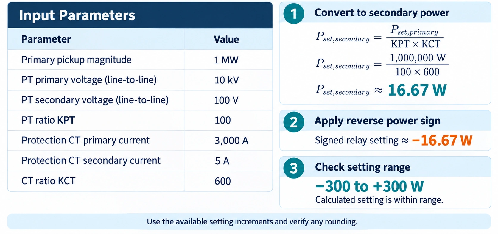
Setting Calculation Summary
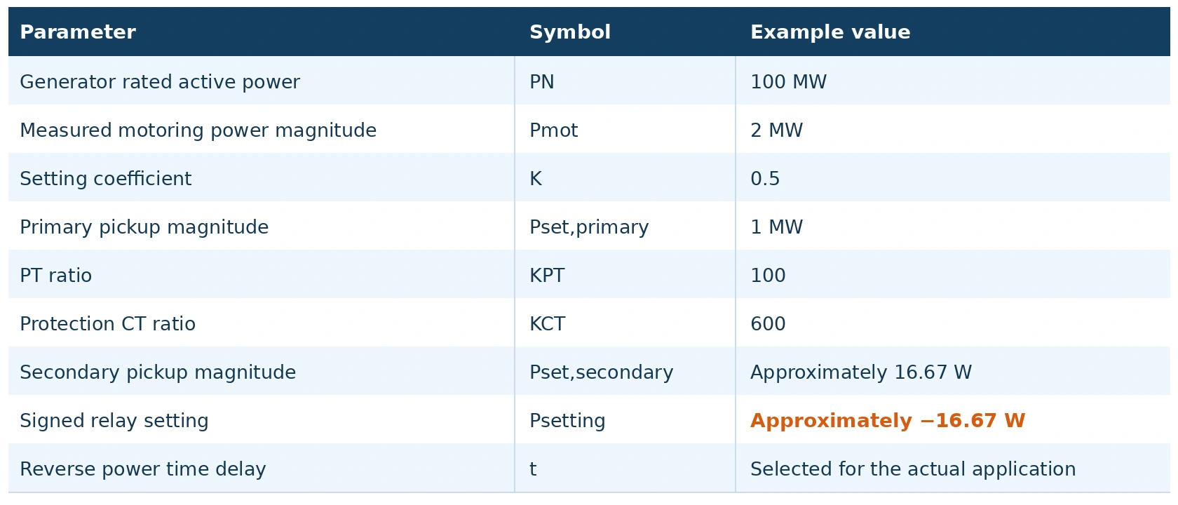
The relay has separate metering CT and protection CT parameter groups. The reverse power calculation uses the protection CT inputs, so the protection CT ratio and polarity must be correctly configured.
5.5 Reverse Power Time Delay Setting
The GWPR300-GB reverse power time delay range is 0–100 s, with a default of 1 s.
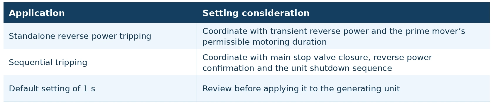
The default delay should not be adopted automatically.
The GWPR300-GB reverse power element does not provide a separate alarm stage. If a short-delay reverse power alarm and a longer-delay trip are required, an additional reverse power stage or suitable external logic is necessary.
5.6 Relay Parameter Settings
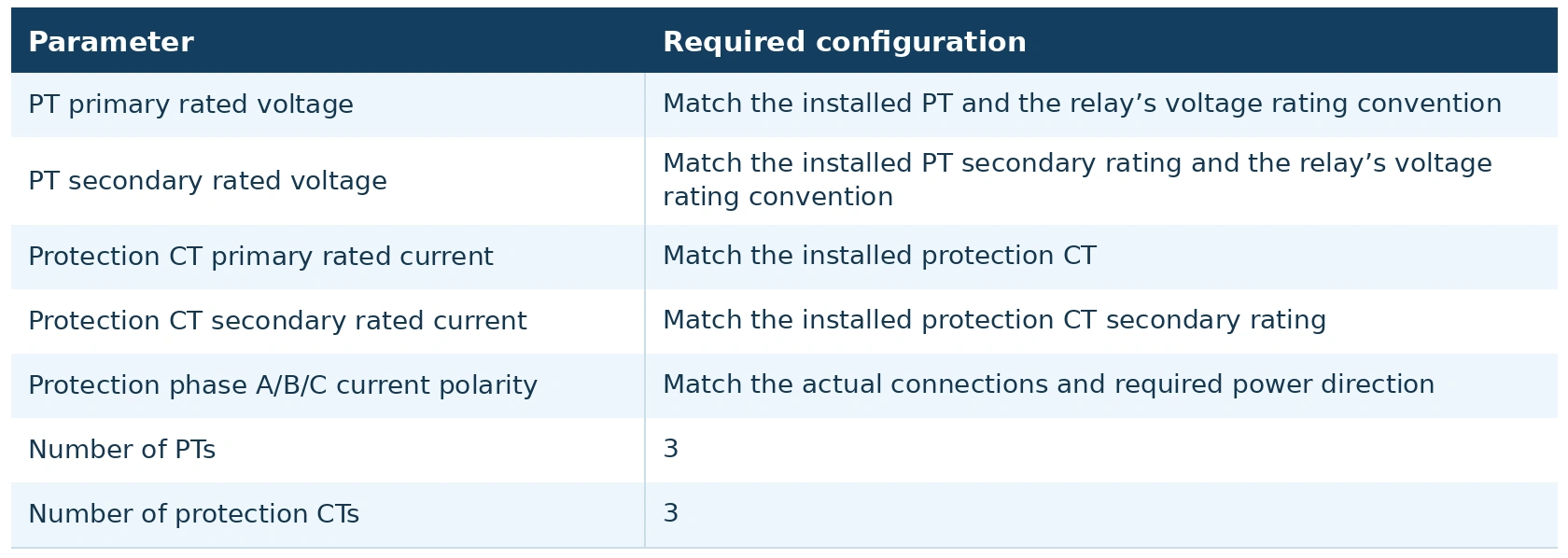
5.6.1 PT and Protection CT Parameters
Before setting and commissioning, confirm the following:
5.6.2 Current Polarity Settings
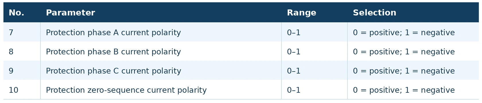
With the direction convention used here, the relay should display positive active power during normal generation and negative active power during motoring.
Incorrect polarity or phase connections can produce an incorrect power direction and cause unwanted reverse power operation.
Verify power direction through on-load checks or coordinated voltage and current injection with a defined phase relationship. Current injection alone does not verify active power direction.
5.6.3 Saving the Settings
5.6.4 Output Configuration
5.7 Setting and Commissioning Procedure
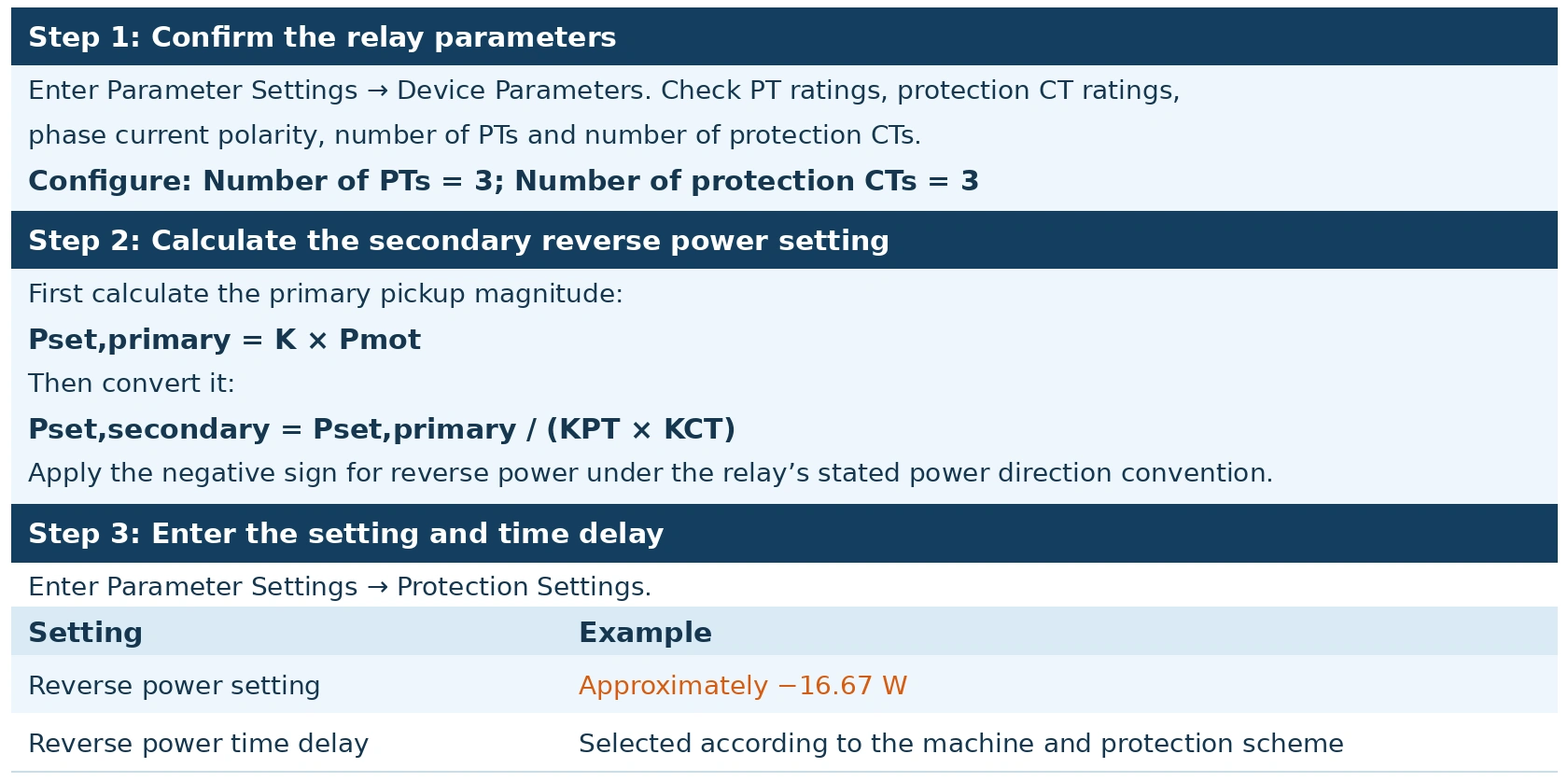
Step 4: Enable reverse power protection
Enter Parameter Settings → Protection Control Word and set the reverse power control word to:
1 = Enabled
Step 5: Save the settings
Exit the setting interface and enter password 1000. Confirm that the settings have been saved.
Step 6: Verify measurement and protection operation
Use Data Browsing → Measured Secondary Values to check the active power magnitude and direction.
Apply voltage and current test signals representing forward and reverse power. Verify the actual pickup threshold, operating time, trip outputs, fault signal and indications.
Use Local Debugging → Output Test to check the assigned output contacts and associated circuits. An output test alone does not verify reverse power measurement or pickup.
Similarly, a current injection test alone cannot verify active power direction. Both voltage and current signals with a defined phase relationship are required.
Step 7: Perform on-load verification
Confirm that the relay displays positive active power during normal generation.
Where required, conduct an approved controlled motoring test to measure the actual motoring power and verify the final setting.
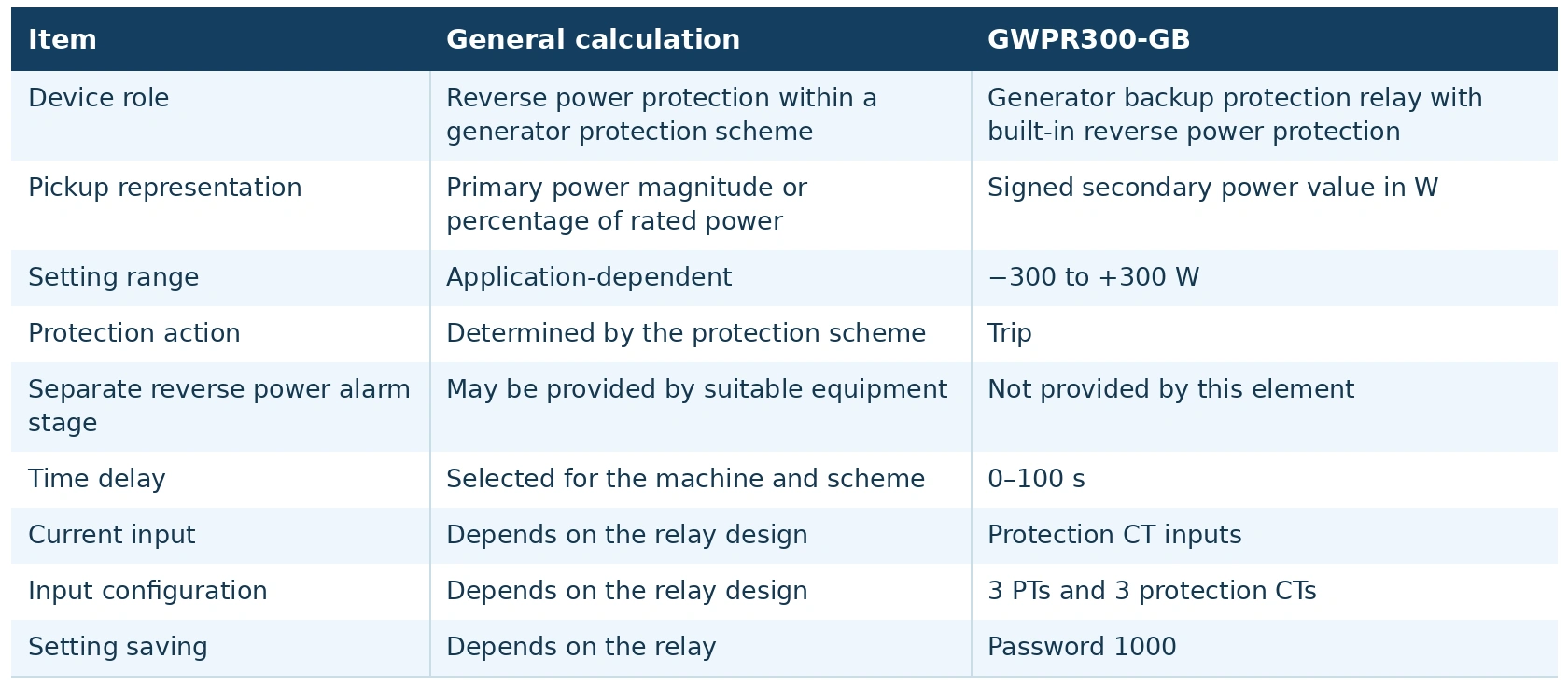
5.8 General Calculation and GWPR300-GB Implementation
VI. Measurement Accuracy and Commissioning Checks
6.1 Low Active Power Measurement
- Reverse power settings can be small relative to generator rated power. Measurement errors that are insignificant during normal generation may therefore become important near the reverse power threshold.
- PT and CT phase displacement is particularly relevant when reactive power is significant and power factor is low. Small phase errors can affect both the calculated active power magnitude and its apparent direction.
- Check the measurement performance at the expected current, active power and power factor. Accuracy under rated conditions alone may not establish suitability for sensitive reverse power protection.
6.2 PT and CT Suitability
- Consider the following:
- PT and CT ratio accuracy and phase displacement.
- Actual secondary circuit burden.
- Performance at the relevant current level.
- Required sensitivity at low active power and low power factor.
- Correct phase sequence, wiring and polarity.
- An accuracy class alone does not guarantee satisfactory reverse power measurement. PT and CT suitability should be assessed together with the relay’s measurement performance and the required pickup setting.
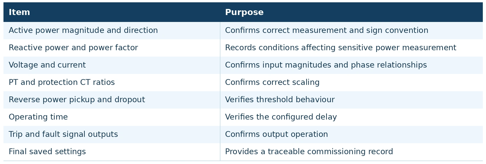
6.3 Commissioning Records
VII. Key Setting Principles
Generator reverse power protection detects active power flowing from the grid into a generator operating as a synchronous motor. Its principal purpose is to protect the prime mover against prolonged motoring.
When applying the GWPR300-GB Generator Backup Protection Relay:
- Define the power direction clearly: generator export is positive, and reverse power is negative.
- Calculate the positive pickup magnitude from the actual motoring power and manufacturer requirements.
- Convert the primary pickup magnitude to secondary watts using the PT and protection CT ratios.
- Apply the correct sign when entering the reverse power setting.
- Coordinate the relay delay and circuit breaker opening time with the permissible motoring duration.
- Configure the PTs, protection CTs and polarity correctly.
- Save the settings with password 1000 and verify measurement, pickup, timing and outputs.
For the example in this article, a primary pickup magnitude of 1 MW corresponds to approximately 16.67 W secondary, using a PT ratio of 100 and a protection CT ratio of 600. The corresponding signed reverse power setting is approximately −16.67 W.
The GWPR300-GB provides this ANSI 32R function within a generator backup protection relay, allowing reverse power protection to be coordinated with the generating unit’s wider protection and shutdown scheme.


