Power Plant SCADA System: Architecture, Components, Functions and Applications
- A Power Plant SCADA System (Supervisory Control and Data Acquisition System) is an essential part of modern power plant electrical automation. It provides real-time monitoring, data acquisition, supervisory control and operational management for generators, power transformers, switchgear, auxiliary electrical distribution systems and associated plant equipment.
- Modern power plant SCADA systems integrate equipment supervision, alarm management, Sequence of Events (SOE) recording, historical data analysis and communication with other automation systems. These capabilities enable operators to monitor plant conditions, identify equipment abnormalities and manage electrical operations from a centralised platform.
- By integrating protection relays, intelligent electronic devices (IEDs), remote terminal units (RTUs), programmable logic controllers (PLCs) and intelligent power meters, a power plant SCADA system improves operational visibility and supports fault investigation, maintenance and reliable plant operation.
1. What Is a Power Plant SCADA System?
A power plant SCADA system is an industrial monitoring and supervisory control system that acquires operational data from power generation equipment through industrial communication networks.
Its primary purpose is to collect and present information from generating units, step-up substations, auxiliary electrical distribution systems and associated equipment through a centralised human–machine interface (HMI).
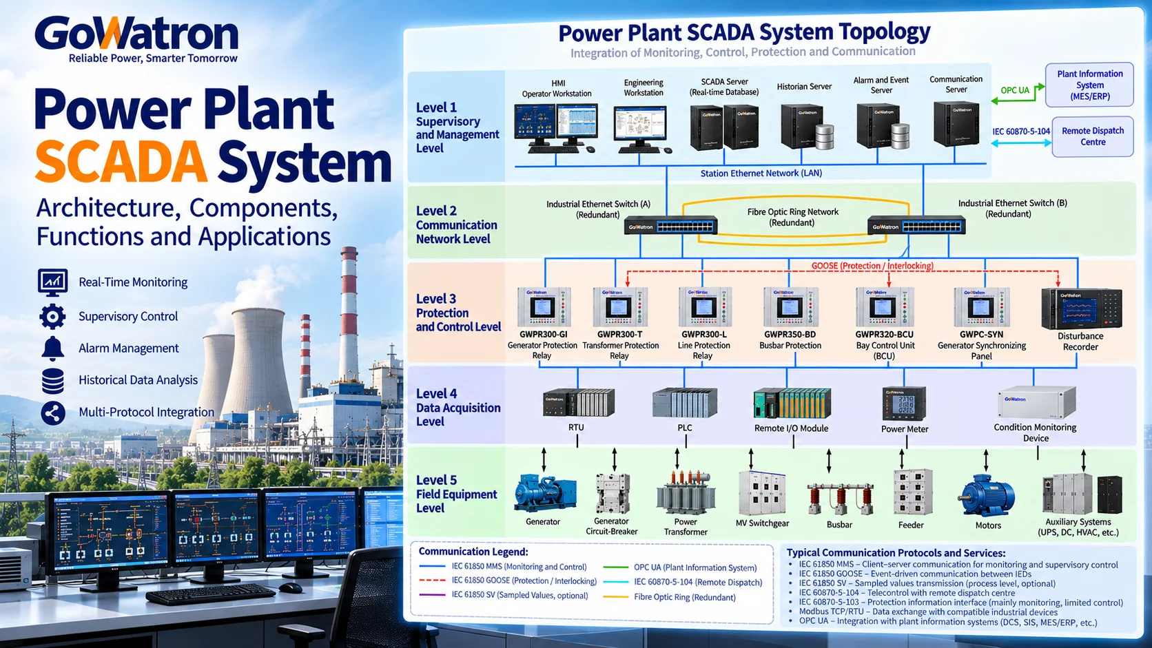
Typical monitored equipment includes:
- Generators and generator circuit-breakers
- Main power transformers and auxiliary transformers
- Medium-voltage (MV) and low-voltage (LV) switchgear
- Busbars, feeders and bus couplers
- Numerical protection relays and other intelligent electronic devices (IEDs)
- Bay control units (BCUs) and dedicated control devices
- Motors and electrical auxiliary equipment
- AC/DC auxiliary power supply systems, uninterruptible power supplies (UPS) and battery systems
- Intelligent power meters and online condition monitoring devices
A power plant SCADA system can provide equipment status monitoring, alarm processing, historical data storage, event recording and authorised remote control.
In applications involving communication with remote dispatch centres, these monitoring and control functions may form part of a wider telecontrol system, using protocols such as IEC 60870-5-104.
Protection and Control Independence
- SCADA is primarily responsible for monitoring and supervisory control. Essential protection functions, including generator differential protection, transformer differential protection and short-circuit fault clearance, must be implemented through appropriately engineered protection systems.
- A failure of the SCADA server or supervisory communication network must not prevent independent protection equipment from detecting faults and initiating the required protective actions.
- IEEE C37.1 provides a reference for SCADA and automation system engineering, including applications in generating stations. Protection-system dependability and independence must also be addressed through the applicable protection standards and project-specific design requirements.
2. Power Plant SCADA System Architecture
A power plant SCADA system typically adopts a distributed architecture that connects supervisory stations, protection and control IEDs, data acquisition equipment and field devices through industrial communication networks.
For functional description, the architecture can be divided into five levels.
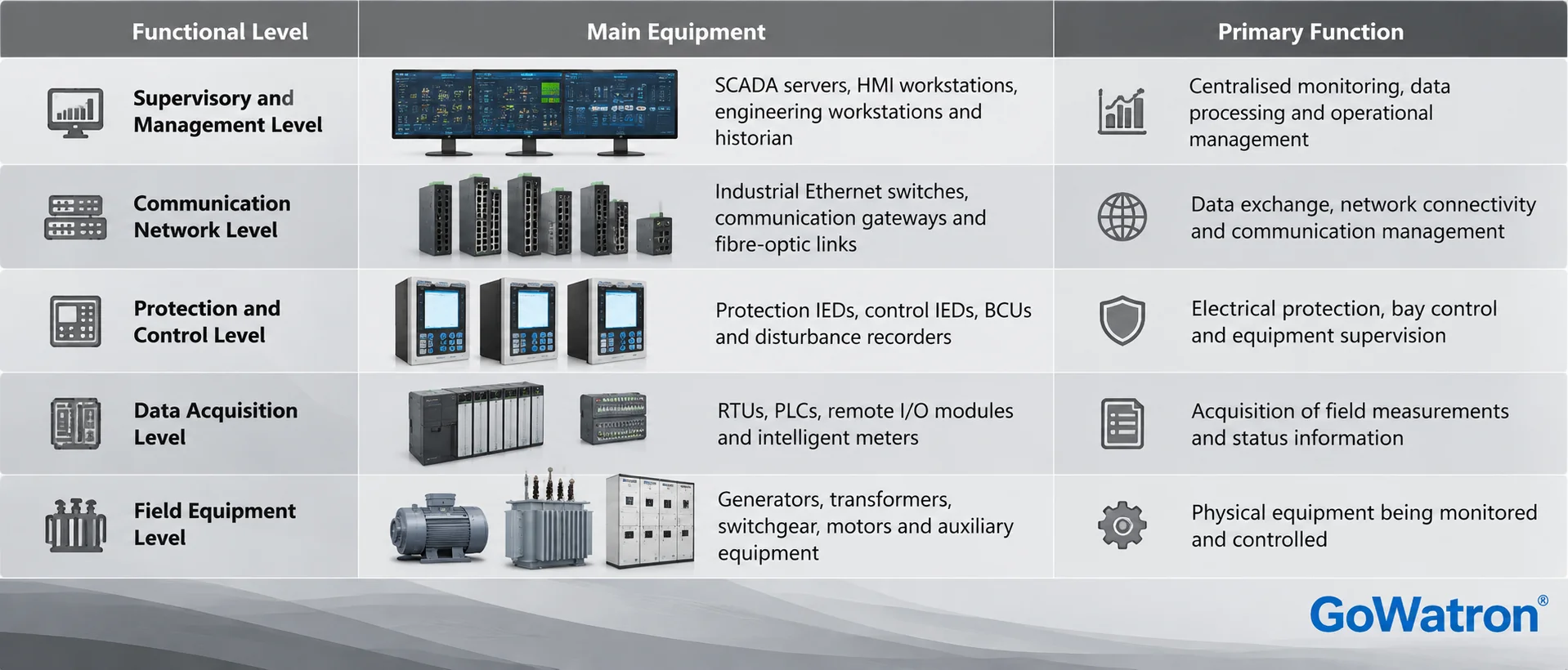
Relationship with IEC 61850 Architecture
The five-level architecture above is a functional engineering representation, not the three-level architectural model commonly used to describe IEC 61850-based substation automation.
IEC 61850-based systems commonly distinguish:
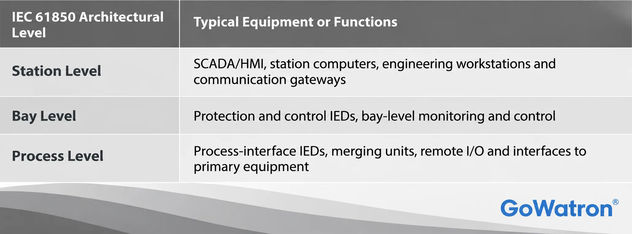
- The communication infrastructure interconnects these levels rather than constituting a separate IEC 61850 architectural level.
- Similarly, the data acquisition and field equipment levels in the five-level functional model do not correspond exactly to the IEC 61850 process level.
- The actual architecture depends on the plant configuration and may include station buses, process buses, direct IED connections and communication gateways.
2.1 Supervisory and Management Level
The supervisory and management level provides centralised monitoring, data processing, operational supervision and system management.
Its principal components include:
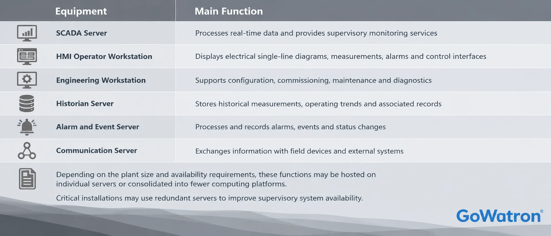
Depending on the plant size and availability requirements, these functions may be hosted on individual servers or consolidated into fewer computing platforms.
Critical installations may use redundant servers to improve supervisory system availability.
2.2 Communication Network Level
The communication network enables data exchange between supervisory systems, protection and control IEDs, controllers and other intelligent devices.
Typical components include:
- Industrial Ethernet switches
- Fibre-optic communication links
- Communication gateways
- Protocol converters
- Industrial firewalls
- Network management equipment
- Time synchronisation equipment
Industrial Ethernet is widely used in modern power plant electrical automation systems.
The network may support different communication services:
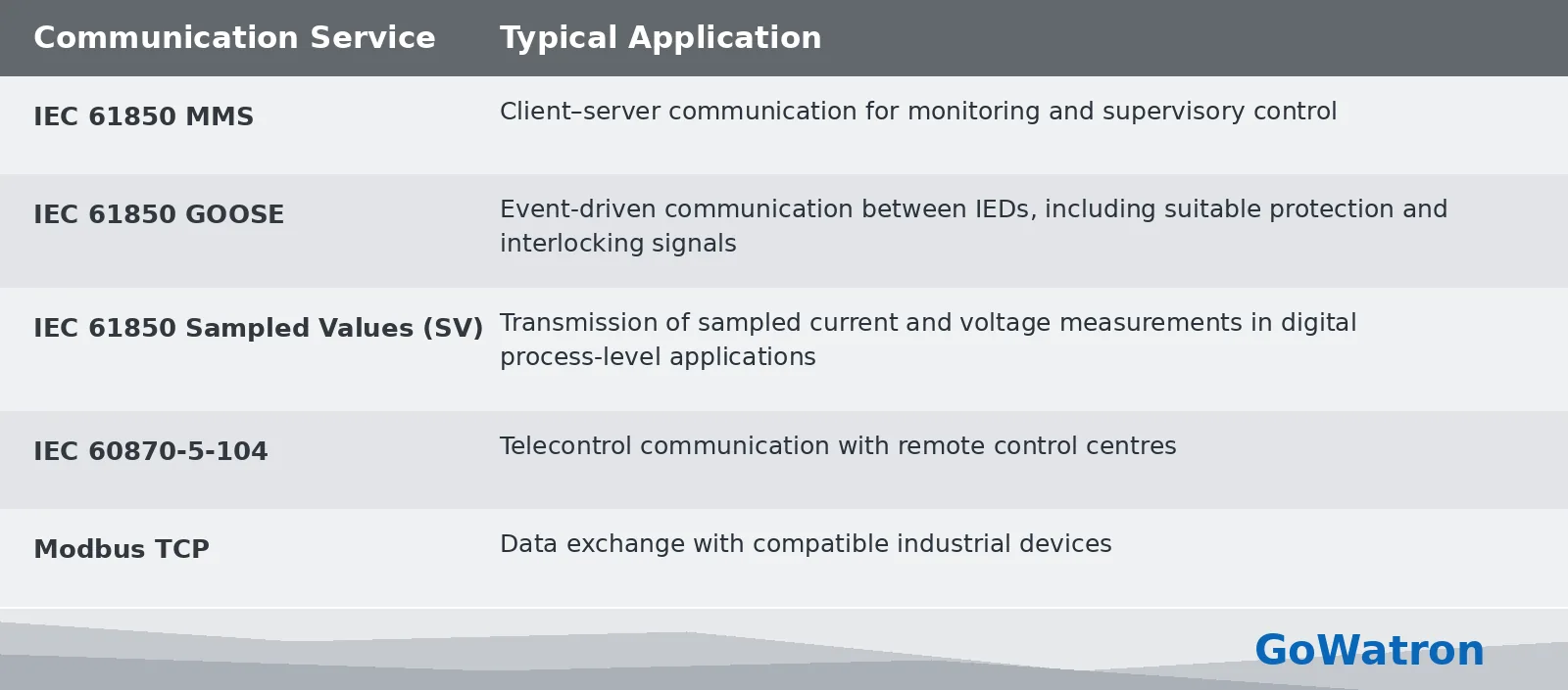
Sampled Values (SV), as specified in IEC 61850-9-2, are primarily used in digital process-level applications. Their implementation depends on the plant architecture and equipment capabilities.
SV is not a mandatory communication service for conventional power plant SCADA systems.
2.3 Protection and Control Level
The protection and control level contains the intelligent devices responsible for electrical protection, local control, bay-level supervision and fault recording.
Typical equipment includes:
- Generator Protection Relay; Detects generator electrical faults and abnormal operating conditions
- Transformer Protection Relay; Provides transformer differential, overcurrent and other protection functions
- Feeder Protection Relay; Detects feeder short circuits, overcurrent and earth faults
- Motor Protection Relay; Provides motor overload, short-circuit, locked-rotor and other protection functions
- Busbar Protection Relay; Detects and clears internal busbar faults
- Bay Control Unit (BCU); Provides bay-level monitoring, switching control and interlocking functions
- Automatic Synchronising Device; Supports synchronism checking and generator or system synchronisation
- Disturbance Recorder; Records fault waveforms, electrical measurements and associated events
Bay Control Units and IEC 61850 Logical Nodes
A Bay Control Unit (BCU) is an established engineering designation for an IED providing bay-level control and monitoring functions.
However, BCU is not a separate logical node class defined by IEC 61850-7-4.
In IEC 61850-based systems, the functions of a bay control IED may be represented by logical nodes such as:
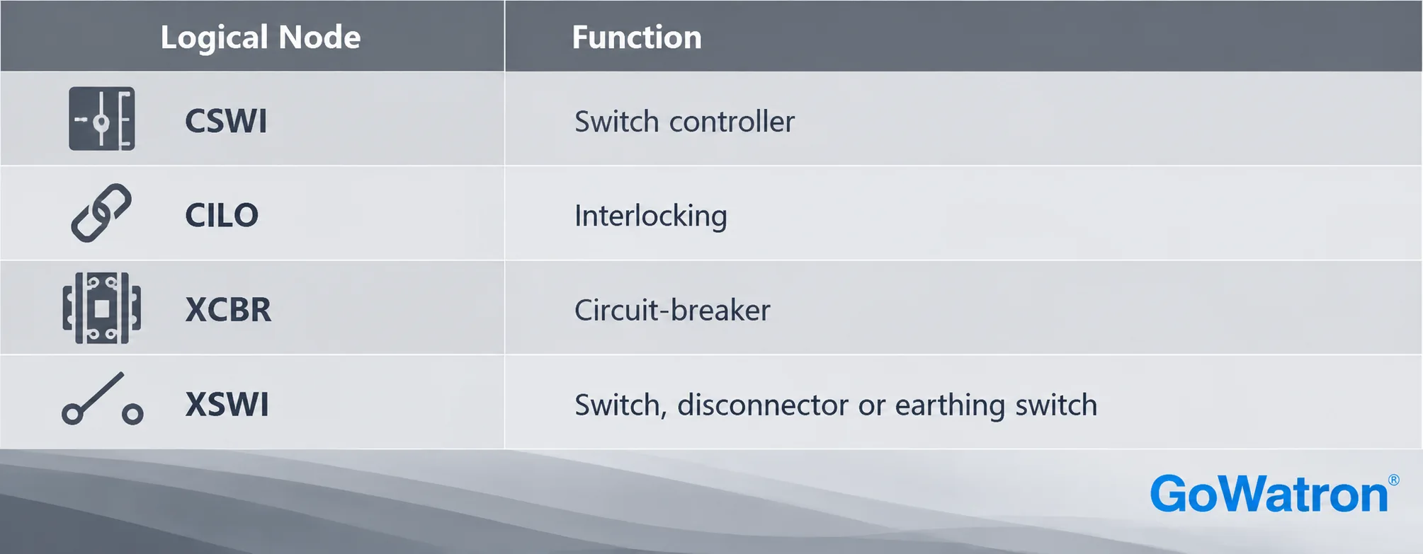
- The actual logical node configuration depends on the device implementation and application.
- Protection IEDs typically provide SCADA systems with electrical measurements, protection operation indications, equipment status and alarms.
- Essential fault detection and protection tripping must remain independent of the availability of the SCADA supervisory platform.
2.4 Data Acquisition Level
The data acquisition level collects measurements, status indications and operational information from field equipment.
Typical devices include:
- Remote terminal units (RTUs)
- Programmable logic controllers (PLCs)
- Remote I/O modules
- Multifunction power meters
- Temperature and pressure sensors
- Level and flow measurement devices
- Equipment condition monitoring devices
The principal data categories include:
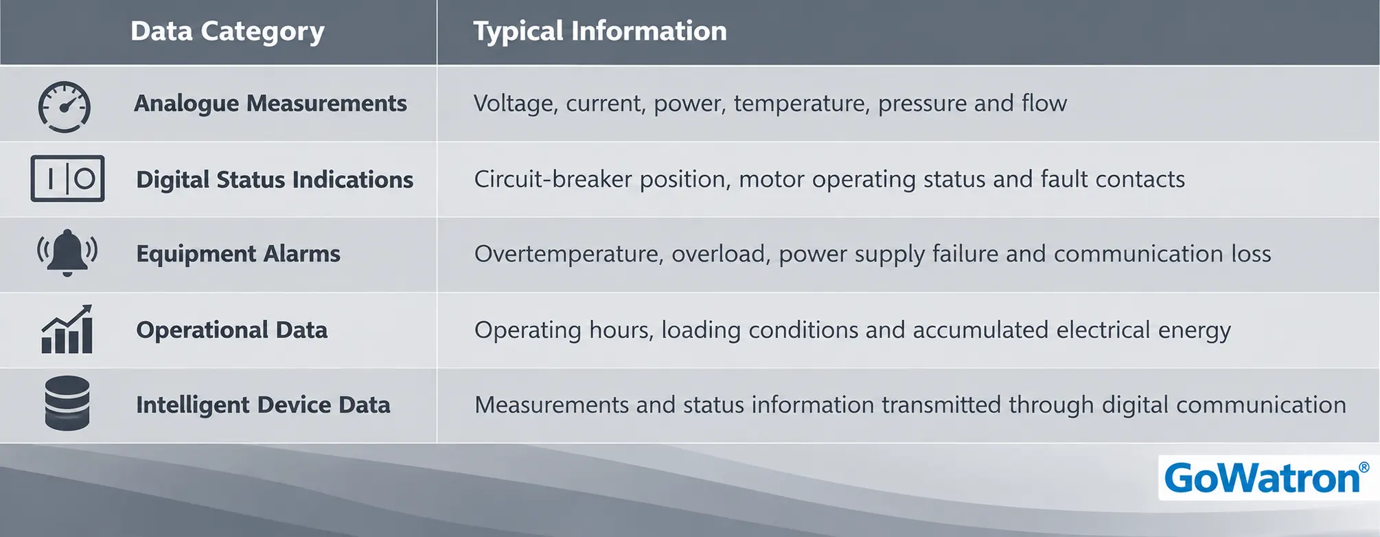
Intelligent devices equipped with compatible communication interfaces may provide data directly to the SCADA network without additional physical I/O modules.
RTUs in Telecontrol Systems
- RTU (Remote Terminal Unit) is an established equipment designation in SCADA and telecontrol engineering.
- In IEC 60870-5-based architectures, a remote site may function as a controlled station, while the supervisory end functions as a controlling station.
- These terms describe roles within a telecontrol system. An RTU may implement controlled-station functions, but the terms are not universally interchangeable because a controlled station may comprise multiple devices.
2.5 Field Equipment Level
The field equipment level comprises the physical equipment monitored and controlled by the SCADA system.
Typical equipment includes:
- Generators
- Power transformers
- Circuit-breakers and disconnectors
- Medium-voltage and low-voltage switchgear
- Busbars and feeders
- Motors, pumps and fans
- AC/DC auxiliary power supply equipment
Equipment configurations vary according to the generating technology and plant design.
For example, thermal power plants typically contain extensive auxiliary electrical distribution systems, while solar power plants require monitoring of inverters, combiner boxes and step-up substations.
3. Main Components of a Power Plant SCADA System
From an equipment configuration perspective, a power plant SCADA system typically comprises seven principal subsystems.
3.1 SCADA Supervisory Station System
The SCADA supervisory station provides centralised monitoring, data processing and operational management.
Its main components include:
- SCADA servers
- Operator workstations
- Engineering workstations
- Real-time databases
- Historical databases
- Alarm and event management software
- Communication management software
The supervisory station typically displays electrical single-line diagrams, equipment operating conditions, real-time measurements, alarm lists, historical trends and authorised control interfaces.
For power plants with multiple generating units, monitoring displays may be organised by generating unit, auxiliary electrical distribution system, step-up substation or operational area.
3.2 Generator Monitoring System
The generator monitoring system supervises generator electrical operating conditions and exchanges relevant information with generator protection, excitation and synchronising equipment.
Typical monitored parameters include:
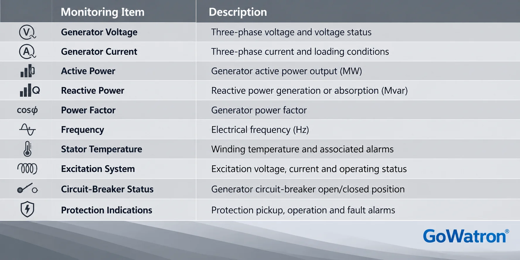
- Available measurements depend on the generator type, sensor configuration and communication interfaces.
- The SCADA system monitors generator operating parameters and protection indications, while generator differential protection, reverse power protection and loss-of-excitation protection are performed by dedicated protection relays.
3.3 Transformer Monitoring System
The transformer monitoring system supervises main power transformers, auxiliary transformers and other important transformers.
Typical monitored information includes:
- HV and LV side voltage and current
- Active and reactive power
- Winding temperature
- Top-oil temperature
- Oil level status
- Cooling fan and oil pump status
- On-load tap-changer position
- Buchholz relay operation indications
- Pressure protection indications
- Differential protection operation indications
For transformers equipped with online condition monitoring systems, dissolved gas analysis (DGA), partial discharge monitoring and other condition monitoring data may also be integrated.
This information helps operators assess transformer loading, temperature, cooling conditions and protection status.
3.4 Switchgear and Auxiliary Electrical Distribution Monitoring System
- Power plant auxiliary electrical distribution systems may operate at several voltage levels.
- Depending on the plant design, common voltage levels include 33 kV, 11 kV, 6.6 kV and 0.4 kV.
SCADA systems can monitor both medium-voltage and low-voltage distribution equipment.
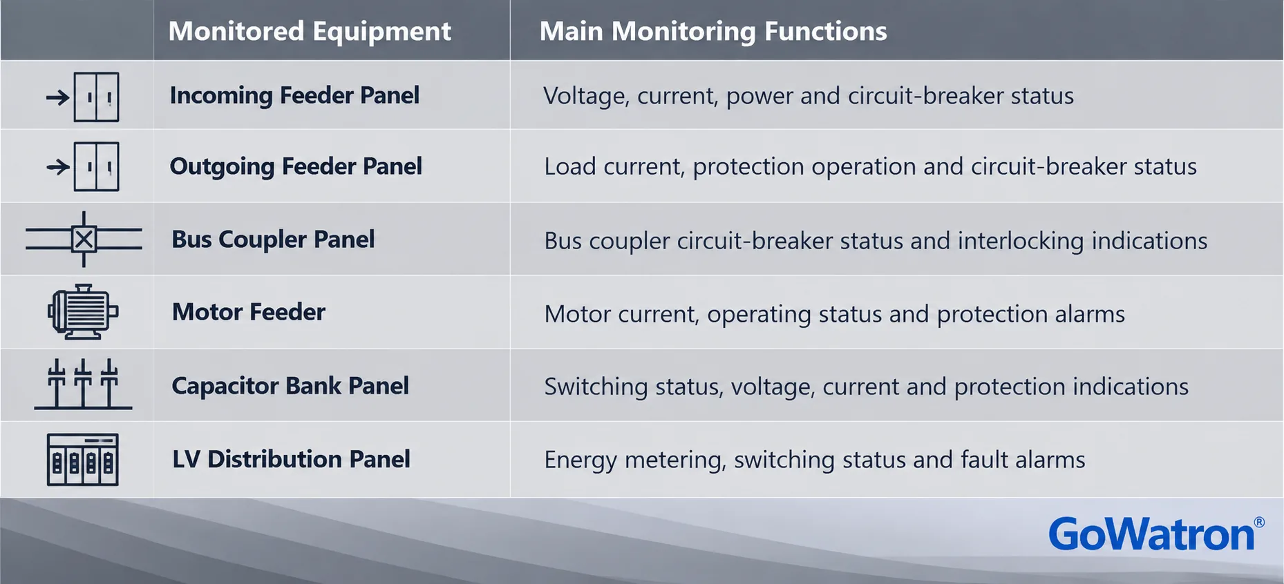
Protection relays, intelligent power meters and bay control IEDs transmit measurements and equipment status information to the SCADA system.
For bays equipped with remote control capabilities, authorised circuit-breaker opening and closing operations may be performed through the appropriate control devices.
3.5 Power Plant Auxiliary System Monitoring
Auxiliary system monitoring collects operational information from electrical and mechanical equipment associated with power plant operation.
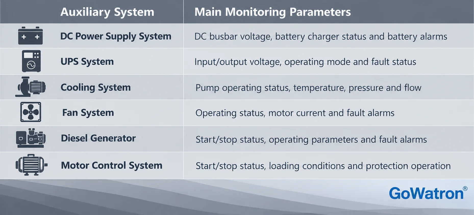
For auxiliary systems equipped with independent controllers, SCADA typically acquires operating status and alarm information through communication interfaces.
Continuous regulation, emergency shutdown and safety interlocking functions must be implemented through appropriately designed dedicated control or safety systems.
3.6 Alarm and Event Recording System
The alarm and event recording system monitors equipment abnormalities, protection operations and changes in operating conditions.
Typical alarms include:
- Generator protection operation
- Transformer differential protection operation
- Feeder overcurrent protection operation
- Unexpected circuit-breaker tripping
- Motor overload
- Abnormal transformer temperature
- DC power supply failure
- UPS failure
- Communication failure
Alarm Records and Sequence of Events (SOE)
- Conventional alarm and event records provide information about abnormal conditions, operator actions and equipment status changes.
- Sequence of Events (SOE) recording supports more precise reconstruction of event sequences, particularly during electrical faults and switching operations.
- SOE systems commonly use millisecond-resolution timestamps where required by the project specification.
- However, timestamp resolution, clock synchronisation accuracy and overall event time accuracy are separate characteristics.
- A timestamp resolution of 1 ms does not necessarily guarantee an absolute timing accuracy of ±1 ms.
- Depending on the application, time synchronisation may use GNSS-based clocks, IRIG-B, NTP/SNTP or IEEE 1588 Precision Time Protocol (PTP).
- The required timing performance must be established according to the plant’s event analysis requirements and the capabilities of the connected devices.
3.7 Historian and Operational Data Analysis System
The historian stores operational measurements and associated event information.
Typical records include:
- Historical active power trends
- Voltage and current variations
- Transformer loading records
- Electrical energy statistics
- Equipment operating hours
- Alarm and event history
- Operational reports
Historical data supports load analysis, fault investigation, equipment maintenance and operational performance assessment.
4. Core Functions of a Power Plant SCADA System
- The principal functions of a power plant SCADA system include real-time monitoring, data acquisition, supervisory control, alarm management, event recording, historical data analysis and communication with other systems.
4.1 Real-Time Monitoring
Real-time monitoring is a fundamental SCADA function.
Through the HMI, operators can view:
- Power plant electrical single-line diagrams
- Generator operating status
- Transformer operating parameters
- Busbar voltage
- Feeder loading
- Circuit-breaker open/closed status
- Auxiliary power supply status
- Equipment alarms
Monitoring displays may be organised by generating unit, electrical distribution area or equipment category.
4.2 Data Acquisition
- The SCADA system acquires operational information from protection IEDs, intelligent power meters, PLCs, RTUs and other connected devices.
- Typical information includes electrical measurements, equipment status indications, fault signals and auxiliary equipment operating parameters.
- Data acquisition may use periodic polling, event-driven reporting or other mechanisms supported by the communication system.
4.3 Supervisory Control and Telecontrol
- A power plant SCADA system may provide authorised remote control of electrical equipment through suitable control IEDs or other dedicated devices.
- In general SCADA terminology, this function is referred to as supervisory control.
- When implemented through remote control systems using IEC 60870-5 protocols, the corresponding application is commonly described as telecontrol.
Typical operations include:
- Circuit-breaker opening
- Circuit-breaker closing
- Start/stop commands for applicable equipment
- Permitted operating mode changes
- Transmission of authorised control setpoints
Remote control operations must satisfy applicable access permissions, equipment status requirements, interlocking conditions and safety requirements.
Control Using IEC 61850
In an IEC 61850-based system, supervisory switching commands can be implemented through the IEC 61850 control model and its MMS mapping.
Relevant logical nodes may include:
- CSWI — Switch controller
- CILO — Interlocking
- XCBR — Circuit-breaker
- XSWI — Switch, disconnector or earthing switch
For example, a control operation may be issued through the controllable Pos data object of a suitable logical node, subject to the configured control model and device implementation.
IEC 61850-7-2 defines four operational control models:
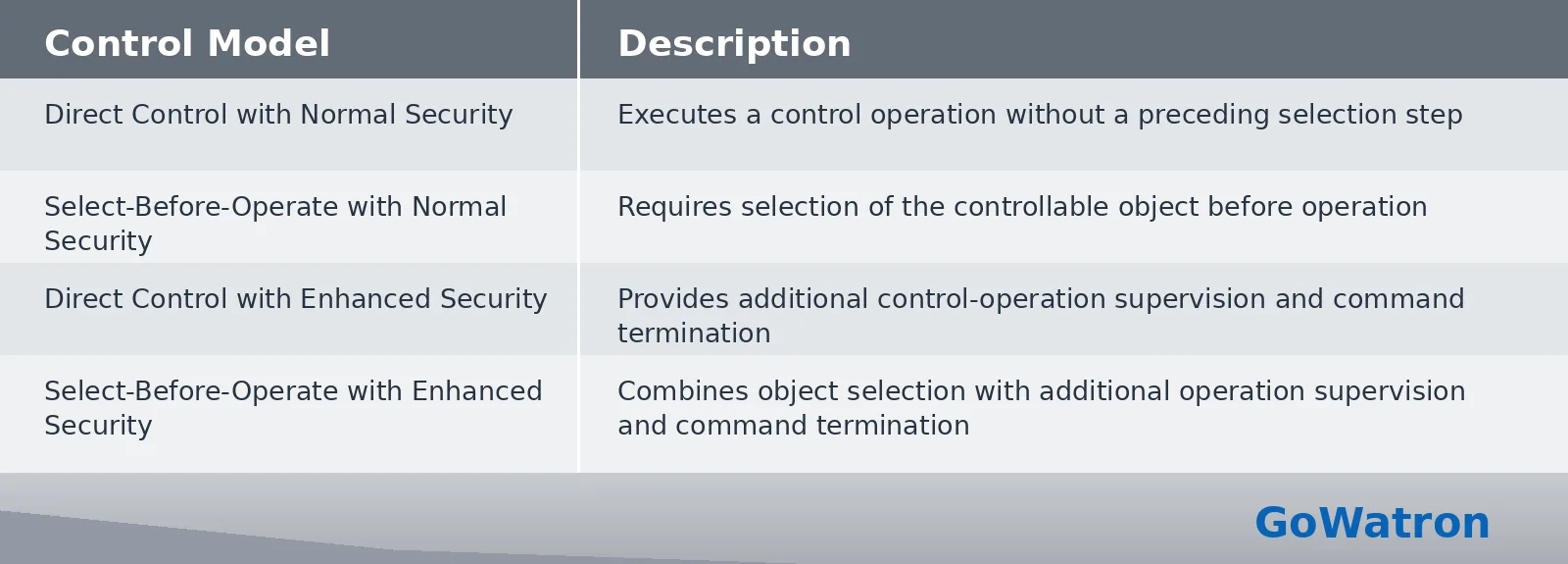
- A separate status-only setting indicates that the object is not controllable through the control model.
- The selected control model depends on the IED implementation, operational requirements and control philosophy.
- In IEC 61850 terminology, enhanced security refers to additional supervision of control execution and command termination. It does not, by itself, indicate encryption, authentication or a higher cybersecurity classification.
- IEC 61850 GOOSE provides event-driven communication for suitable high-speed IED-to-IED applications, including protection trip indications and interlocking signals.
- GOOSE is not the default replacement for MMS-based SCADA operator control commands. Its use for trip or interlocking functions must be specifically engineered and validated.
Control Using IEC 60870-5-104
In IEC 60870-5-104 telecontrol applications, commands may be exchanged between a controlling station and a controlled station.
Examples of command Application Service Data Unit (ASDU) types include:
- C_SC_NA_1 — Single command
- C_DC_NA_1 — Double command
Depending on the equipment and application, command execution may use direct execution or select-before-operate procedures.
Command validity, control authority and the applicable interlocking requirements must be verified before execution.
4.4 Alarm Management
The SCADA system generates alarms based on information received from connected equipment and configured alarm conditions.
Alarm management typically includes:
- Alarm display
- Alarm classification
- Alarm prioritisation
- Alarm acknowledgement
- Alarm history
- Alarm clearance status
Effective alarm management helps operators identify abnormal conditions promptly and prevents important alarms from being obscured by excessive low-priority notifications.
4.5 Sequence of Events Recording
Event recording captures equipment status changes, control operations and protection operations.
Typical events include:
- Protection relay operation
- Circuit-breaker tripping
- Circuit-breaker closing
- Control command execution
- Communication status changes
SOE recording supports fault investigation by providing a time-ordered record of significant events.
Where accurate event sequencing is required, the system must provide suitable time synchronisation, timestamp resolution and event time accuracy.
4.6 Historical Trending and Data Analysis
The SCADA system stores selected operational measurements in a historical database.
Historical trend displays allow operators to analyse:
- Generator active power variations
- Load variations
- Voltage fluctuations
- Transformer temperature changes
- Motor operating conditions
- Electrical energy consumption
Historical data can also support operational reporting and maintenance analysis.
4.7 System Communication and Integration
The SCADA system exchanges information with different types of intelligent devices and external systems.
Typical connected equipment includes:
- Protection relays
- Bay control IEDs
- PLCs and RTUs
- Intelligent power meters
- Transformer online monitoring devices
- AC/DC power supply monitoring devices
- Grid dispatch communication equipment
Common communication protocols and services include:
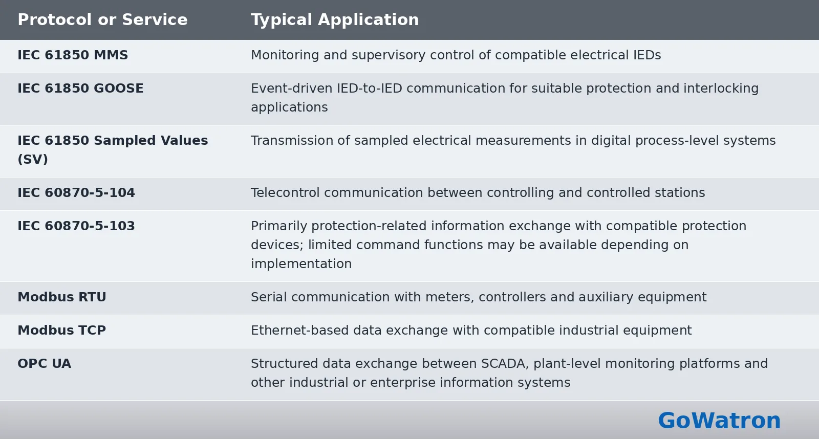
- OPC UA may be used to integrate SCADA with plant information platforms, other control or monitoring systems, and higher-level manufacturing or enterprise applications, where supported.
- IEC 60870-5-103 is primarily intended for communication with protection equipment. Although certain command functions are supported, it should not be presented as equivalent to a comprehensive telecontrol solution based on IEC 60870-5-104.
- The selection of communication protocols and services depends on equipment capabilities, system architecture, interoperability requirements and the intended application.
5. Applications of Power Plant SCADA Systems
5.1 Thermal Power Plants
In thermal power plants, SCADA systems are primarily used for centralised monitoring of generators, transformers, auxiliary electrical distribution systems and associated electrical equipment.
Typical monitored equipment includes:
- Generators and generator circuit-breakers
- Main power transformers
- Auxiliary transformers
- Medium-voltage switchgear
- Low-voltage distribution systems
- Motors and electrical auxiliary equipment
- AC/DC auxiliary power supply systems
The SCADA system provides centralised visibility of equipment operating conditions, protection operations and alarm information, together with suitable supervisory control capabilities.
5.2 Hydroelectric Power Plants
In hydroelectric power plants, SCADA systems monitor hydroelectric generating units, electrical equipment and associated auxiliary systems.
Typical monitored equipment and parameters include:
- Hydroelectric generating units
- Generator electrical measurements
- Main power transformers
- Switchgear
- Water levels and relevant hydraulic parameters
- Auxiliary equipment
- Protection and control devices
Depending on the scope of plant automation, the SCADA system may exchange operational information with unit controllers, turbine governor systems and other dedicated control systems.
5.3 Gas-Fired Power Plants
In gas-fired power plants, SCADA systems primarily monitor generators and associated electrical equipment.
Typical applications include:
- Generator monitoring
- Generator protection status monitoring
- Main power transformer monitoring
- Auxiliary electrical distribution monitoring
- Auxiliary power supply monitoring
- Grid dispatch communication
Gas turbine control and safety protection are performed by appropriate dedicated systems.
5.4 Solar Power Plants
In solar power plants, SCADA systems provide centralised monitoring of PV inverters, combiner boxes, step-up transformers and other electrical equipment.
Typical monitored equipment includes:
- PV inverters
- PV combiner boxes
- Package substations
- Medium-voltage switchgear
- Electrical energy meters
- Meteorological monitoring equipment
- Step-up substation equipment
For solar power plants subject to grid dispatch requirements, the SCADA system may exchange operational information with the power plant controller and grid dispatch system.
6. Conclusion
- A Power Plant SCADA System is an important component of power plant electrical automation and operational monitoring. It provides real-time monitoring, data acquisition, supervisory control, alarm management and historical data analysis for generators, transformers, switchgear, auxiliary electrical distribution systems and associated equipment.
- A typical functional architecture comprises supervisory and management, communication network, protection and control, data acquisition and field equipment levels. These functional groupings can be related to the station, bay and process-level arrangements used in IEC 61850-based electrical automation systems, although the two architectural descriptions are not directly equivalent.
- Modern SCADA systems integrate numerical protection relays, control IEDs, RTUs, PLCs and intelligent measuring devices through suitable industrial communication networks.
- IEC 61850 supports standardised IED information models and communication services, while IEC 60870-5-104 supports telecontrol applications. Protection and critical safety functions remain the responsibility of appropriately engineered protection and dedicated control systems.
- Through suitable system architecture, equipment integration and functional configuration, power plant SCADA systems improve operational visibility, support fault investigation and equipment management, and contribute to safe, reliable and efficient operation across thermal, hydroelectric, gas-fired and solar power generation facilities.
7. Technical References
The following standards and technical documentation provide useful references for power plant SCADA engineering and communication system design:
- IEC 61850-7-2; Abstract Communication Service Interface (ACSI), including control models
- IEC 61850-7-4; Logical node classes and data object classes
- IEC 61850-8-1; Communication service mappings for MMS and GOOSE
- IEC 61850-9-2; Sampled Values communication mapping
- IEC 60870-5-103; Companion standard for the informative interface of protection equipment
- IEC 60870-5-104; Network access for IEC 60870-5-101 telecontrol applications
- IEEE C37.1-2007; Reference standard for SCADA and automation systems; currently inactive-reserved


