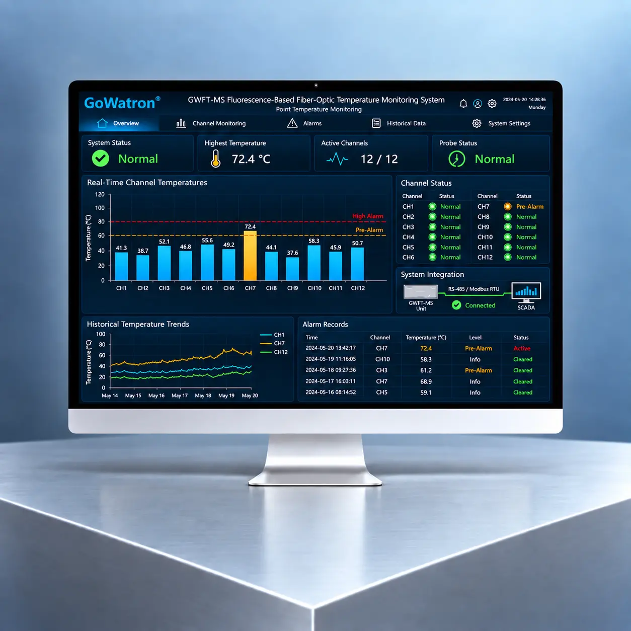
GWFT-MS Fluorescence-Based Fiber-Optic Temperature Monitoring System
- The GWFT-MS Fluorescence-Based Fiber-Optic Temperature Monitoring System, developed and manufactured by GoWatron, is a point-type fiber-optic temperature monitoring system based on fluorescence lifetime thermometry. It is designed for high-voltage equipment, environments with strong electromagnetic interference, confined spaces, and other applications where conventional electrical temperature sensors may be unsuitable.
- The system transmits excitation light to a fluorescent temperature probe through an optical fiber and receives the returning fluorescence signal. The optoelectronic signal conditioner determines the real-time temperature at each measurement point using the calibrated relationship between fluorescence lifetime and temperature.
- The sensing probe uses a passive optical design and requires no power supply or electronic circuitry at the measurement point. It does not create a direct electrical connection between high-voltage primary equipment and low-voltage monitoring systems, providing effective electrical isolation and excellent immunity to electromagnetic interference.
- The GWFT-MS is suitable for online temperature monitoring of critical points in medium- and high-voltage switchgear, dry-type transformers, liquid-immersed transformers, high-power variable-frequency drives, power conversion systems, energy storage systems, industrial microwave equipment, and other demanding electromagnetic environments.




Product Functions
Multi-Channel Real-Time Temperature Monitoring
- The system supports 1 to 12 temperature measurement channels. Additional channels can be provided according to project requirements.
- It continuously acquires and displays the real-time temperatures of multiple critical measurement points.
Multi-Level Temperature Alarms
- Independent pre-alarm and high-temperature alarm thresholds can be set for each measurement channel. When a threshold is reached, the system can trigger local alarms, relay outputs, communication-based alarms, and remote indications.
- Alarm reset values, time delays, and hysteresis can be configured according to the selected model and project requirements.
Temperature Trend Monitoring
- With data-logging functionality or supervisory software, the system can display individual temperature trend curves and compare temperatures across multiple measurement points.
- The recorded data can support abnormal temperature-rise assessment, equipment condition monitoring, and maintenance planning.
Alarm and Control Interlocking
The system can transmit alarm signals to protection, control, or supervisory systems through relay contacts or communication interfaces. These signals can be used to:
- Start cooling fans
- Activate ventilation or cooling equipment
- Generate remote alarms
- Initiate load-reduction measures
- Activate predefined interlocking logic
If the temperature signal is used to initiate circuit-breaker tripping, the GWFT-MS alarm output should be integrated into a properly engineered and validated protection or interlocking scheme. The trip command should be issued by the protection or control system, not by the temperature monitor alone.
Communication and Remote Monitoring
The system can incorporate an RS-485 communication interface supporting the Modbus RTU protocol. It can be integrated with:
- Supervisory Control and Data Acquisition (SCADA) systems
- Substation automation systems
- Electrical power monitoring systems
- Energy management systems
- Equipment condition monitoring platforms
- Programmable logic controllers
- Industrial control systems
Ethernet interfaces and additional communication protocols are available as optional features, subject to the selected system configuration.
Historical Data Management
With onboard data storage or supervisory software, the system can provide:
- Historical temperature data storage
- Temperature trend curves
- Comparison of multiple measurement points
- Overtemperature event records
- Alarm and system fault records
- Data query and export
- Temperature report generation
System Condition Monitoring
Depending on the selected configuration, the system can detect:
- Broken optical fibers
- Insufficient optical signal strength
- Measurement channel failures
- Communication failures
- Signal conditioner operating abnormalities
When an abnormal condition is detected, the system can provide a local indication, relay output, or communication-based fault indication.
System Components
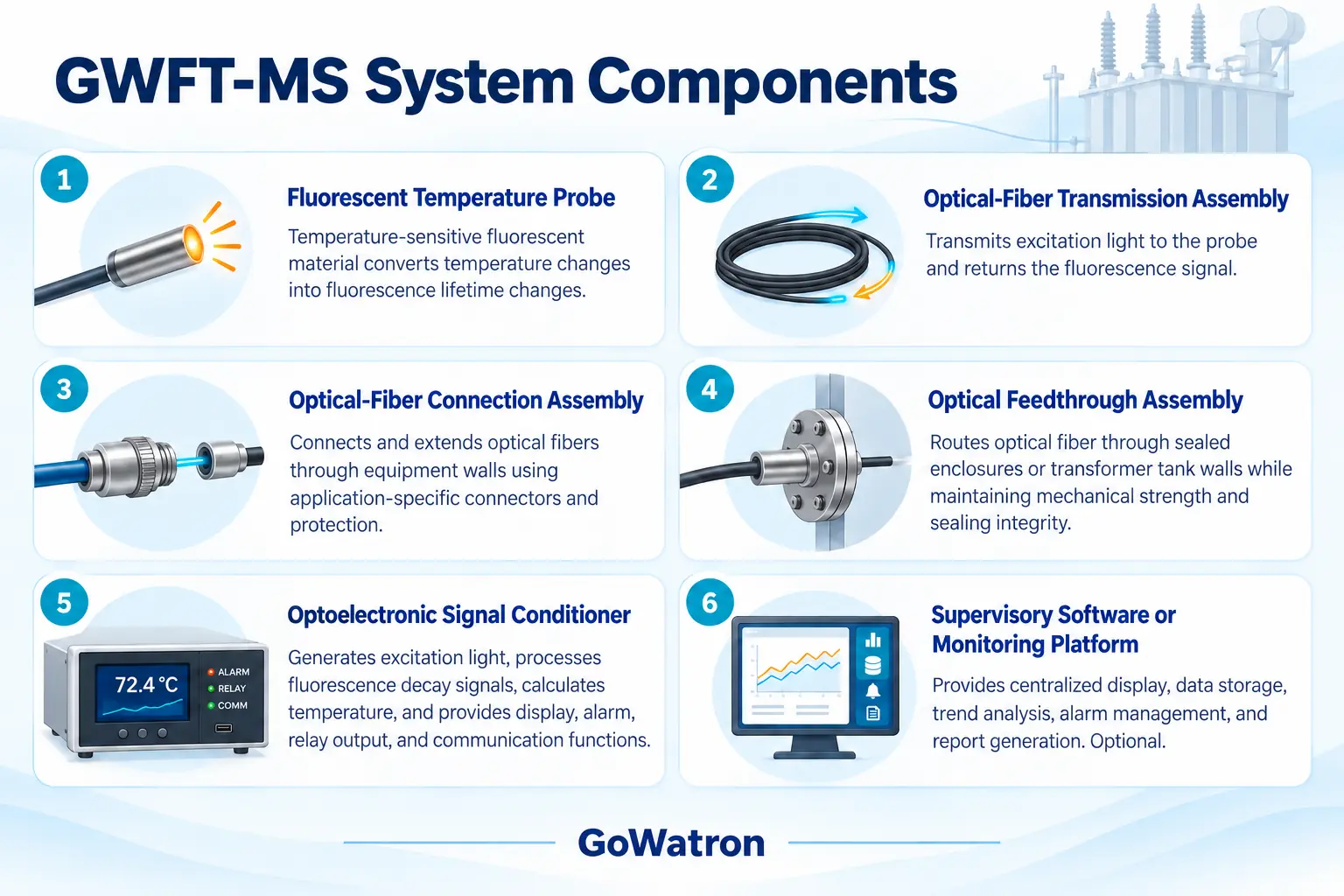
The GWFT-MS uses a modular architecture and mainly consists of the following components:
Optical-Fiber Connection Requirements
- The optical-fiber connector type, fiber length, protective sheath material, and feedthrough arrangement should be selected according to the actual application environment.
- The internal conditions of switchgear, variable-frequency drives, dry-type transformers, and liquid-immersed transformers differ significantly. Therefore, it is inadvisable to specify a single connector type, such as ST, a fixed fiber length, or a uniform sheath material for all applications.
- For liquid-immersed transformer applications, dedicated probes, optical fibers, and tank-wall feedthrough assemblies should be used. These components must be compatible with the insulating liquid and satisfy the applicable requirements for long-term thermal endurance, mechanical strength, pressure resistance, and sealing integrity.
Operating Principle
The GWFT-MS operates on the principle of fluorescence lifetime thermometry.
- The signal conditioner emits excitation light at a specific wavelength. The excitation light travels through an optical fiber to the fluorescent temperature probe installed at the measurement point. The temperature-sensitive fluorescent material at the probe tip emits fluorescence after being optically excited.
- When the excitation light is switched off, the fluorescence intensity gradually decays. For an ideal fluorescence response that can be represented by a single-exponential model, the decay can be approximated as:\( I(t) = I₀ × e^(−t/τ) \);
Where:
- I(t) is the fluorescence intensity at time t.
- I₀ is the initial fluorescence intensity.
- τ is the fluorescence lifetime or fluorescence decay time constant.
- t is the elapsed time after the excitation light is switched off.
- The fluorescence lifetime, τ, changes predictably with temperature. The signal conditioner acquires the fluorescence decay signal, calculates the fluorescence lifetime, and converts it into a temperature value using the probe-specific calibration curve or mathematical model.
- The relationship between fluorescence lifetime and temperature is generally not strictly linear. Different types of fluorescent probes therefore require calibration data corresponding to their respective temperature-sensitive materials.
- Because fluorescence lifetime measurement is primarily based on timing characteristics rather than absolute signal intensity, it is generally less sensitive to variations in light-source output, connector insertion loss, and moderate optical-path attenuation than intensity-based measurement methods.
- However, excessive fiber bending, contaminated connectors, broken fibers, damaged probes, or severe optical signal attenuation may still affect measurement reliability.
Key Advantages
Passive Optical Sensing Probe
- The sensing probe contains no battery or electronic circuitry at the measurement point and requires no local power supply. It is suitable for installation at high electrical potential, in areas with strong electromagnetic interference, and in confined spaces.
Effective Electrical Isolation
- Measurement signals are transmitted optically, so the sensing path does not create a direct electrical connection between high-voltage primary equipment and low-voltage monitoring systems.
Suitability for a specific rated voltage must be verified by considering:
- Probe materials
- Optical-fiber sheath construction
- Installation position
- Fiber routing
- Electrical clearances
- Creepage distances
- Insulation coordination
- Overall equipment insulation design
Excellent Immunity to Electromagnetic Interference
The optical transmission path is not directly affected by power-frequency magnetic fields, radio-frequency interference, or electromagnetic noise generated by power electronic equipment.
The system is therefore suitable for:
- Medium- and high-voltage switchgear
- Power transformers
- Variable-frequency drives
- Power conversion systems
- Energy storage converters
- Industrial microwave equipment
- Radio-frequency heating equipment
Direct Measurement of Critical Temperatures
The probe can be installed at or near contacts, busbar joints, windings, power modules, and other critical heat-generating locations.
Direct temperature measurement can help identify:
- Increased contact resistance
- Loose electrical connections
- Equipment overload
- Cooling system abnormalities
- Localized overheating
- Abnormal temperature differences between phases
Continuous Multi-Point Monitoring
- Multiple fluorescent fiber-optic probes can be connected to the system for continuous temperature monitoring at several critical locations.
- Each measurement channel can display its temperature independently and can be assigned individual alarm thresholds.
Low Maintenance Requirements
The probe has a simple passive construction and contains no battery requiring periodic replacement at the measurement point.
Routine maintenance mainly involves inspecting:
- Optical fibers
- Optical connectors
- Probe mounting arrangements
- Optical feedthrough assemblies
- Signal conditioner operation
Actual probe service life and calibration intervals depend on operating temperature, mechanical stress, fiber aging, installation conditions, and product-specific requirements.
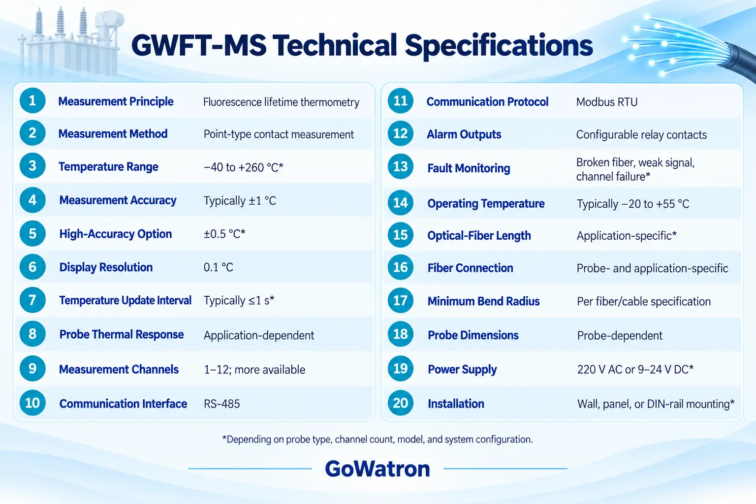
Main Technical Specifications
The following values represent typical GWFT-MS configuration ranges. Final specifications are subject to the selected probe type, number of channels, product configuration, and project technical agreement.
Temperature Update Interval and Thermal Response Time
The temperature update interval and probe thermal response time are different parameters.
- Temperature update interval: The time required for the signal conditioner to calculate and update a temperature value
- Probe thermal response time: The time required for the sensing probe to respond to a change in the temperature of the measured object or medium
Probe thermal response is affected by:
- Probe dimensions
- Probe construction
- Mounting method
- Thermal interface material
- Contact pressure
- Characteristics of the measured surface
- Airflow or liquid-flow conditions
For this reason, a generic response-time claim, such as “less than 1 second,” should be avoided unless verified under specified test conditions.
Rated Voltage and Insulation Considerations
The fluorescent temperature probe uses a passive optical sensing method. However, suitability for a particular system voltage depends on the complete installation arrangement rather than the probe alone.
The following factors must be considered:
- Probe and optical-fiber materials
- Optical-fiber sheath construction
- Electrical clearances
- Creepage distances
- Optical-fiber routing
- Probe installation position
- Equipment insulation coordination
- Power-frequency withstand voltage
- Lightning impulse withstand voltage
Therefore, a blanket statement such as “100 kV probe withstand voltage” should not be used as a universal rating unless the test method, electrode arrangement, test duration, and complete installation configuration are explicitly defined.
For equipment with rated voltages of 11 kV, 22 kV, 33 kV, or above, suitability should be verified according to the complete installation structure, insulation coordination requirements, and applicable test results.
Applications
Medium- and High-Voltage Switchgear
The GWFT-MS can monitor the temperature of:
- Circuit-breaker contact areas
- Disconnector connection points
- Busbar joints
- Cable terminations
- Primary-circuit bolted connections
- Other locations susceptible to abnormal temperature rise
The number of measurement points should be determined according to the primary circuit arrangement. Typical configurations include three, six, or nine measurement points per switchgear panel.
The probes must be installed where they can accurately represent the temperature of the monitored connection without adversely affecting electrical clearances, creepage distances, insulation performance, or mechanical operation.
Typical applications include switchgear and controlgear rated at 11 kV, 22 kV, 33 kV, and other project-specific voltage levels.
Dry-Type Transformers
Probes can be installed near predicted winding hot spots, core areas, terminal connections, or other critical locations to monitor:
- Winding temperature rise
- Overload-related heating
- Cooling fan failure
- Inadequate ventilation
- Temperature imbalance between phases
- Abnormal terminal heating
Probe locations, mounting methods, and optical-fiber routing should be determined during transformer design or manufacturing to avoid adversely affecting the insulation structure, local electric-field distribution, or cooling performance.
Typical applications include dry-type transformers with primary rated voltages of 11 kV, 22 kV, or 33 kV.
Liquid-Immersed Power Transformers
Direct online monitoring of winding hot-spot temperature can be achieved by embedding dedicated fluorescent fiber-optic probes near predicted winding hot spots and using tank-wall optical feedthroughs, sealing assemblies, and external extension fibers.
The following requirements must be considered:
- Compatibility of probes and optical fibers with the insulating liquid
- Long-term thermal endurance
- Oil or ester resistance of the fiber sheath
- Pressure resistance and sealing integrity of tank-wall feedthroughs
- Effects on winding insulation
- Effects on local electric-field distribution
- Resistance to mechanical vibration and liquid flow
- Transformer manufacturing and factory test requirements
Direct winding hot-spot monitoring should generally be incorporated during transformer manufacture or major overhaul.
Installing a standard probe directly in the insulating liquid will measure only the liquid temperature at that location. This must not be presented as direct winding hot-spot measurement unless the probe is correctly positioned within or immediately adjacent to the winding hot-spot region.
The system can be applied to power transformers at internationally common rated voltage levels such as 33 kV, 66 kV, 110 kV, 132 kV, 220 kV, 400 kV, and above, provided that the transformer design, insulation coordination, installation engineering, and validation testing confirm its suitability.
Variable-Frequency Drives and Power Electronic Equipment
The system can be used to monitor:
- Areas near IGBT or SiC power modules
- Rectifier and inverter units
- DC busbar connections
- Reactors
- Internal transformers
- Heat sinks
- Critical insulation components
Probe installation must not compromise power-module packaging, electrical clearances, creepage distances, cooling structures, or the equipment’s original safety design.
Energy Storage Systems
The GWFT-MS can monitor critical temperature points in:
- Power conversion systems
- Step-up transformers
- DC collection connections
- Medium-voltage distribution units
- High-current busbar connections
- Other critical heat-generating components
For temperature measurement inside battery cells or battery modules, the probe and optical fiber must be separately evaluated for flame retardance, chemical resistance, electrical insulation, mechanical compatibility, and applicable battery energy storage system safety requirements.
Industrial Microwave and Radio-Frequency Equipment
- Fluorescent fiber-optic probes are not directly affected by strong electromagnetic fields, making them suitable for industrial microwave systems, radio-frequency heating equipment, and other environments where conventional electrical temperature sensors may not operate reliably.
Other Industrial Applications
The GWFT-MS can also be used in:
- High-voltage test equipment
- Petrochemical installations
- Iron and steel production equipment
- Rubber and plastics processing machinery
- Precision machine tools
- Power generation equipment
- Railway and transit electrical systems
- Other applications requiring electrical isolation and immunity to electromagnetic interference
Medical equipment and patient temperature monitoring are regulated medical applications. They require dedicated products with the appropriate safety design, validation, and regulatory approvals and are not included within the standard industrial application scope of the GWFT-MS.


