Generator Negative-Sequence Overcurrent Protection (ANSI 46): Principles, Functions and Setting Calculations
1. Protection Configuration Overview
- Generator negative-sequence overcurrent protection (ANSI 46) detects stator negative-sequence current arising from power-system unbalance and protects the rotor against the resulting thermal damage. It responds primarily to phase-to-phase faults, phase-to-phase-to-ground faults, open-conductor conditions, incomplete-pole operation of circuit breakers, and prolonged severe load unbalance. A single-phase-to-ground fault may also produce negative-sequence current, but its magnitude depends on the generator neutral-grounding method and system sequence impedances. ANSI 46 therefore cannot replace dedicated stator earth-fault protection such as ANSI 64G.
- Medium and large generators are typically equipped with definite-time and inverse-time negative-sequence overcurrent functions. The inverse-time function is coordinated with the rotor thermal characteristic and is the principal means of protecting the rotor against negative-sequence heating. The definite-time function is used mainly for abnormal-condition alarms; where required by the unit protection scheme, an additional definite-time trip stage may be provided as backup protection for unbalanced faults and abnormal conditions.
2. Protection Operating Principle (Rigorous Engineering Version)
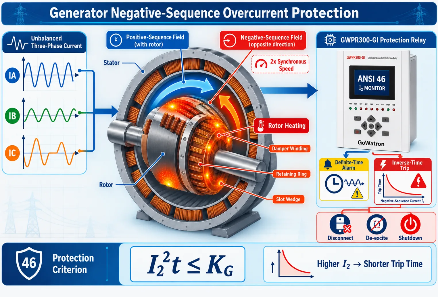
- Under balanced three-phase operating conditions, the stator current contains only a positive-sequence component. The resulting magnetic field rotates synchronously with the rotor in the same direction, so there is no relative motion capable of producing additional negative-sequence heating in the rotor.
- When an unbalanced fault or operating condition occurs, negative-sequence current flows in the stator and produces a magnetic field rotating in the direction opposite to the rotor. Relative to the rotor, this field rotates at twice the synchronous angular speed and induces currents in the rotor body, damper winding, slot wedges, and retaining rings.
- The relative motion induces double-frequency currents and eddy currents at \( 2f_N \) in the rotor surface, slot wedges, retaining rings, and damper winding—approximately 100 Hz in a 50 Hz system and 120 Hz in a 60 Hz system. Concentrated surface currents can cause localized rotor overheating, metal scorching, and thermal deformation of retaining rings; in severe cases, they can damage the damper system and field winding. An ideal symmetrical three-phase fault contains no negative-sequence component and therefore does not operate this protection.
3.Generator Rotor Negative-Sequence Withstand Characteristic (Core Criterion)
Rotor negative-sequence heating follows a thermal accumulation principle. The allowable short-term thermal withstand criterion for generator rotors is adopted as follows:
\[ I_{2*}^2 \cdot t \le K_G \]
Parameters:
- All current values are per-unit quantities based on the generator rated stator current \( I_N \) Primary or secondary current values in amperes shall not be substituted directly into the formula.
- \( I_{2*} \): Per-unit value of stator negative-sequence current
- \( t \): Duration of asymmetric fault (s)
- \( K_G \): Generator rotor short-term negative-sequence thermal capacity constant. Priority shall be given to manufacturer-provided design parameters or negative-sequence withstand curves. If manufacturer data is unavailable, values shall be selected per applicable IEC/IEEE standards considering rotor structure, unit capacity, cooling method, and damper configuration.
Mechanism explanation: Hydrogenerators generally use salient-pole rotors with large dimensions, relatively long thermal time constants, and robust damper structures. Turbo-generators generally use cylindrical rotors whose surface components may have lower short-term thermal capacity. Differences in negative-sequence withstand capability depend on rotor construction, cooling method, machine rating, and damper design—not simply on heat-dissipation performance.
4. Inverse-Time Operating Equation (General Rigorous Model)
- Considering the continuously permissible negative-sequence current, steady-state negative-sequence losses, and heat dissipation, some digital generator protection relays use the following inverse-time thermal model. It is not a universal standard equation; implementations vary among manufacturers.
\[ t=\dfrac{K_{\mathrm{set}}}{I_{2*}^{\ 2}-I_{2\infty*}^{\ 2}} \]
-
\( I_{2*} \): Measured stator negative-sequence current in per unit
-
\( I_{2\infty*} \): Continuously permissible generator negative-sequence current in per unit. A typical engineering reference range is 0.05–0.10, but the actual value shall be taken from the manufacturer’s continuous negative-sequence current capability data.
-
\( K_{\mathrm{set}} \): Negative-sequence thermal-capacity setting of the relay, derived from the generator withstand constant\( K_G \) with an appropriate safety margin and in accordance with the relay algorithm.
-
\( t \): Theoretical protection operating time (s)
Supplementary note: Depending on the manufacturer, a relay may use pure \( I_2^2t \) integration, a percentage thermal-capacity model, or a coupled heating-and-cooling model. Actual settings shall be calculated using the operating equation specified in the applicable relay manual.
Operating logic: When \( I_{2*}\le I_{2\infty*} \), the negative-sequence current is within the continuously permissible range. The relay generally does not initiate its tripping thermal accumulator, although the rotor still experiences additional losses and temperature rise within permissible limits. When \( I_{2*} \gt I_{2\infty*} \), inverse-time thermal accumulation begins; the higher the negative-sequence current, the faster the heat accumulation and the shorter the operating time.
A minimum operating time \( t_{\min} \)is applied to ensure stable negative-sequence measurement, symmetrical-component calculation, and thermal-model integration, and to coordinate with generator and transformer differential protection. No universal fixed range applies. This example uses 0.5 s for illustration; the actual value shall be determined from the relay manual and the project protection-coordination study. If the calculated operating time is less than \( t_{\min} \), the relay operates after \( t_{\min} \).
5. Protection Functions (Precise Engineering Definition)
- Core function: Continuously monitors stator negative-sequence current and detects unbalanced short circuits, open-phase conditions, and severe load unbalance. Its delayed trip characteristic is coordinated with the rotor thermal withstand capability, making it the dedicated protection against rotor overheating caused by negative-sequence current.
- Definite-time stage: Normally used to alarm for prolonged mild unbalance or excessive steady-state negative-sequence current. On some older small and medium-sized units, two definite-time stages may be applied—a low-set alarm stage and a high-set delayed trip stage—the latter serving as backup protection for unbalanced faults. These stages do not replace the inverse-time rotor thermal protection.
- Inverse-time stage: Approximates the rotor thermal accumulation characteristic and provides inverse-time tripping. Depending on the unit design, operation may initiate generator disconnection, de-excitation, and unit shutdown to prevent continued rotor heating.
- Protection scope limitation: Does not respond to symmetrical three-phase short circuits or symmetrical overloads that produce no negative-sequence components.
6. Setting Calculation (Complete Rigorous Engineering Version)
6.1 Definite-Time Negative-Sequence Overcurrent Protection (46-1)
- Setting principle: The pickup setting shall be above the maximum steady-state negative-sequence current occurring during normal operation and minor load fluctuations.
\[ I_{2.set*} = K_{rel} \cdot I_{2\infty*} \]
- Parameter selection: In the absence of project-specific criteria, a security factor of \( K_{rel}=1.2\sim1.3 \) and an alarm delay of 5–10 s may be used as engineering references to ride through transient load disturbances. Final settings shall be based on the measured maximum steady-state negative-sequence current, the manufacturer’s continuous capability, and site operating requirements.
- Configuration note: The definite-time stage is primarily designed for steady-state unbalance alarming. For large and medium units with defined negative-sequence thermal withstand characteristics, inverse-time protection shall be adopted as the main thermal protection; definite-time tripping shall not replace inverse-time thermal protection.
6.2 Inverse-Time Negative-Sequence Overcurrent Protection (46-2, Principal Trip Stage)
6.2.1 Pickup Setting
- The pickup current is set slightly above the continuously permissible negative-sequence current to avoid operation during permissible steady-state unbalance:
\[ I_{2.op*}=1.05\sim1.1 \cdot I_{2\infty*} \]
- These values are engineering references. The actual pickup depends on the relay thermal model and unit operating conditions and shall be established by the formal setting study. For the model described here, the tripping thermal accumulator starts only when the measured negative-sequence current exceeds the pickup setting.
6.2.2 Sensitivity and Thermal Coordination Verification
- Sensitivity verification: For the minimum system operating condition, calculate the minimum negative-sequence current seen by the relay for the unbalanced conditions within its intended coverage, including phase-to-phase faults, phase-to-phase-to-ground faults, open conductors, and incomplete-pole operation of circuit breakers. The sensitivity factor is:
\[ K_{\mathrm{sen}} =\dfrac{I_{2,\min *}}{I_{2,\mathrm{op}*}} \]
- Thermal coordination verification is also required. Within the relay’s valid inverse-time operating range above pickup and the applicable range of the manufacturer’s curve, compare the relay operating characteristic with the generator negative-sequence withstand characteristic. At each relevant negative-sequence current level, the relay shall operate before the rotor withstand time is exceeded. The assessment shall also consider alarm delay, operator response time, and the clearing times of other fault protections; a single-point check is insufficient. The short-term thermal model shall not be extrapolated indefinitely into the low-current region, where the manufacturer’s complete negative-sequence capability curve shall govern.
7. Engineering Calculation Example (With Thermal Safety Margin Illustration)
Given: turbo-generator rating \( S_N=62.5\,\text{MVA} \), rated voltage \( U_N=10.5\,\text{kV} \), and rated stator current \( I_N=3437\,\text{A} \). The manufacturer specifies a short-term negative-sequence withstand constant of \( K_G=15 \) and a continuously permissible negative-sequence current of \( I_{2\infty*}=0.08 \) per unit. This example illustrates the calculation method only and shall not be used directly as a field setting.
1. Definite-time alarm stage setting:
- Take \( K_{rel}=1.2 \), \( I_{2.set*}=1.2\times0.08=0.096 \), primary operating current \( I_{2.set}=0.096\times3437 = 330\,\text{A} \),alarm delay 8 s.
2. Inverse-time protection setting:
- Pickup setting \( I_{2.op*}=1.1\times0.08=0.088 \); for illustration, the minimum operating time is \( t_{\min}=0.5\,\text{s} \).
- Thermal-margin setting: To illustrate the margin between the relay operating curve and the rotor withstand curve, this example assumes that the relay algorithm permits use of a reduction factor \( K_s=0.85 \). The factor and method are illustrative only; actual settings shall be based on the manufacturer’s withstand curve, the relay algorithm, and the project setting criteria.
- Relay thermal-capacity setting: \( K_{\mathrm{set}}=K_s \cdot K_G=0.85\times15=12.75 \)
- Relay operating equation used in this example: \( t_{\mathrm{op}}=\dfrac{12.75}{I_{2*}^2-0.08^2} \)
- Fault condition: \( I_{2*}=0.8 \)
\[ t_{\mathrm{op}}=\dfrac{12.75}{0.8^2-0.08^2}\approx20.1\,\text{s} \]
- Engineering conclusion: From the generator short-term withstand criterion \( I_{2*}^2t=K_G \), the rotor withstand limit for this condition is \( t_G=\dfrac{15}{0.8^2}\approx23.44\,\text{s} \). The calculated relay operating time of approximately 20.1 s is earlier than this limit and provides a single-point time margin of approximately 14.2%. Because the generator short-term withstand model and the relay thermal model have different mathematical forms, satisfactory coordination at one point does not demonstrate coordination over the entire range. A complete comparison is required over the relay’s valid inverse-time operating range and the applicable range of the manufacturer’s withstand curve. The short-term adiabatic model shall not be extrapolated directly into the low negative-sequence current region.
8. Key Engineering Notes
- No dedicated negative-sequence CT is required. The relay calculates negative-sequence current from the three phase-current inputs using a symmetrical-component algorithm. Digital relays commonly provide CT-circuit supervision; depending on the relay logic, a CT-circuit abnormality may initiate an alarm, blocking, or another response. The selected logic shall balance security against false operation with dependability during genuine system faults.
- The trip outputs of the inverse-time negative-sequence protection shall be selected according to the generator-transformer connection, generator circuit-breaker arrangement, excitation system, and unit shutdown philosophy. A severe negative-sequence thermal condition generally results in generator disconnection and, as required by the unit design, coordinated de-excitation and prime-mover shutdown or a programmed unit shutdown.
- Differences in negative-sequence withstand capability between hydrogenerators and turbo-generators arise from rotor construction, thermal capacity, cooling method, machine rating, and damper design. The capability shall not be assigned solely by generator type; use the manufacturer’s technical data or negative-sequence withstand curve for the specific unit.
- The minimum operating time \( t_{\min} \) is the lower operating-time limit of the inverse-time function. It supports stable negative-sequence measurement and thermal-model calculation and permits appropriate coordination with generator differential, transformer differential, and other relevant protection functions. Its value shall be determined from the relay manual and the project protection-setting study.
- Many digital generator protection relays provide negative-sequence thermal memory and cooling-recovery functions. They can accumulate the thermal effects of intermittent unbalanced conditions and reduce the stored thermal state after fault clearance according to a cooling characteristic. The integration algorithm, cooling time constant, and behavior following loss of auxiliary power shall be confirmed in the applicable relay documentation.


