Motor Thermal Overload Protection (ANSI 49): Operating Principle and Setting Calculations
1. What Is ANSI 49 Protection?
- ANSI 49 is a protection function designed to prevent motor damage caused by excessive temperature and accumulated thermal stress. It is commonly referred to as:
- Motor Thermal Overload Protection
- Motor Thermal Model Protection
- Motor Thermal Replica Protection
- The function uses motor current, operating time, current unbalance, cooling conditions, and the initial thermal state to establish a mathematical thermal model. It continuously estimates the motor’s thermal capacity used (TCU). When the calculated thermal state reaches a specified threshold, the relay issues an alarm or trip command.
- ANSI 49 differs from definite-time or inverse-time overcurrent protection. Rather than simply determining whether the current exceeds a fixed threshold, it simulates the motor’s heating, thermal accumulation, and cooling processes. It can therefore account for prolonged overloads, frequent starts, and incomplete cooling after shutdown.
- The equations presented in this article are based on a simplified first-order thermal model. Actual relay algorithms may include multiple time constants, separate running and standstill cooling models, negative-sequence compensation, ambient-temperature compensation, and RTD biasing. Final settings must therefore be based on the applicable relay manual.
2. Functions of ANSI 49 Protection
- Motor thermal overload protection is primarily intended to prevent motor overheating caused by:
- Prolonged overload operation;
- Excessive mechanical loading;
- Excessively long starting time;
- Locked-rotor or stall conditions;
- Thermal accumulation caused by frequent starts;
- Three-phase current unbalance;
- Phase-loss operation;
- Cooling-fan failure or inadequate ventilation;
- Excessive ambient temperature;
- Restarting the motor before it has cooled sufficiently.
- Phase loss and severe current unbalance should normally be detected and cleared promptly by ANSI 46 negative-sequence or current-unbalance protection. ANSI 49 can include the additional heating caused by current unbalance in its thermal calculation and provide thermal backup protection.
- ANSI 49 can account for the rapid thermal accumulation caused by a locked-rotor or stall condition. However, these conditions should normally also be detected by excessive-starting-time protection, locked-rotor or stall protection, or overcurrent protection to provide faster and more clearly defined operation.
- ANSI 49 is particularly suitable for detecting moderate overcurrents that may not be extremely high but persist long enough to cause overheating. Severe motor internal faults or short circuits are normally cleared rapidly by instantaneous overcurrent protection (ANSI 50), time-overcurrent protection (ANSI 51), or motor differential protection (ANSI 87M).
3. Operating Principle
3.1 Motor Heating Principle
- The copper loss in the motor stator winding can be approximated by:
-
\[ P_Cu = I² × R \]
The heat generated by the winding is therefore approximately proportional to the square of the current and the duration of current flow:
-
\[ Q∝I2t \]
The higher the current, the faster the motor temperature rises. The longer the current persists, the greater the accumulated thermal energy.
- However, the motor also dissipates heat to its surroundings. Numerical motor protection relays therefore use a thermal model that represents both heat generation and heat dissipation.
- A basic relay may use a first-order thermal model with one heating time constant and one cooling time constant. More sophisticated relays may use multiple thermal parameters to represent:
- Running and standstill cooling conditions;
- Stator and rotor thermal characteristics;
- Positive-sequence and negative-sequence heating;
- Motor starting and locked-rotor conditions;
- Ambient-temperature effects;
- RTD-based temperature biasing.
- The specific thermal-model algorithm should always be confirmed from the relay manufacturer’s documentation.
3.2 Thermal-State Calculation
- For a simplified first-order thermal model, when the equivalent thermal current remains constant, the motor thermal state can be expressed as:
\[ H(t) = M² − (M² − H₀) × e^(−t/τ_h) \]
where:
- \( H(t) \) is the calculated thermal state at time \(t\);
- \( H_0 \) is the initial thermal state;
- \( M \) is the equivalent thermal-current multiple;
- \( \tau_h \) is the motor heating time constant;
- \( t \) is the elapsed operating time.
- The equivalent thermal-current multiple is:
\[ M = \frac{I_{\mathrm{eq}}}{I_{\theta}} \]
where:
- \( I_{\mathrm{eq}} \)is the equivalent thermal current;
- \( I_{\theta} \) is the thermal reference current.
- If the protection relay uses a normalized thermal-state scale from 0 to 1, the thermal capacity used can be expressed as:
\[ \mathrm{TCU} = H \times 100\% \]
- TCU stands for Thermal Capacity Used.
- Under this normalized model:
\[ H_0 = \frac{\mathrm{TCU}_0}{100} \]
- For example, if the relay indicates a current TCU of 60%:
\[ H_0=0.60 \]
- Different protection relays may use different definitions and internal scaling methods for thermal state and TCU. If the relay does not use the normalized model described above, the manufacturer’s conversion and operating equations must be used.
Typical operating logic includes:
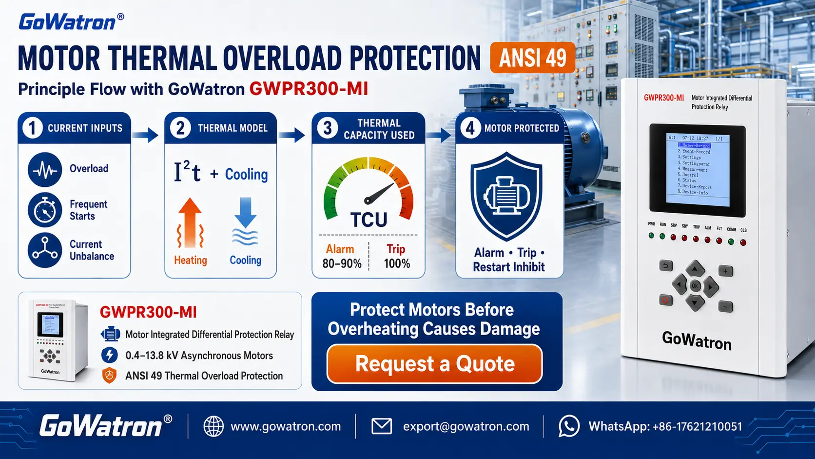
- TCU reaches 80%–90%: thermal-overload alarm;
- TCU reaches 100%: thermal-overload trip;
- After the motor stops, TCU decreases according to the cooling model;
- A restart is inhibited if the predicted remaining thermal capacity is insufficient for one normal start.
- Alarm thresholds, trip thresholds, restart-inhibit conditions, and thermal-memory retention may vary between protection relays.
3.3 Motor Cooling Model
- After the motor is stopped, its internal temperature does not immediately return to ambient temperature. Under a simplified first-order cooling model, the thermal state decreases exponentially:
\[ H(t)=H_0e^{-t/\tau_c} \]
where:
\( H_0 \) is the thermal state at the beginning of the cooling period;
\( t_c \) is the motor cooling time constant;
\( t \) is the cooling time.
For a motor equipped with a shaft-mounted cooling fan, the fan stops when the motor is de-energized. Heat dissipation is therefore normally lower during standstill than during operation, and the standstill cooling time constant is generally greater than the running heating time constant.
When manufacturer data are unavailable, the following range is sometimes used as a preliminary engineering estimate:
\[ \tau_c=(2\text{–}4)\tau_h \]
- This range must not be treated as a universal setting rule. The final cooling time constant should be determined from:
- Motor manufacturer data;
- Motor construction;
- Cooling method;
- Ventilation conditions;
- Whether the cooling fan remains operational after shutdown;
- Actual site operating conditions.
- If the motor uses independently powered forced ventilation, its standstill cooling conditions may be closer to those during normal operation. Nevertheless, the setting must reflect the actual availability and operating logic of the cooling system.
4. Effect of Current Unbalance on the Thermal Model
- Three-phase current unbalance or phase-loss operation produces negative-sequence current. The negative-sequence magnetic field rotates in the opposite direction relative to the rotor and may produce substantial additional rotor losses and heating.
- Some motor protection relays use the following form of negative-sequence thermal compensation:
\[ I_{\mathrm{eq}} = \sqrt{I_1^2+K_2I_2^2} \]
where:
\( I_1 \)is the positive-sequence current;
\( I_2 \) is the negative-sequence current;
\( K_2 \) is the negative-sequence heating factor.
- Because negative-sequence current normally produces more severe rotor heating than an equal magnitude of positive-sequence current, the thermal model applies a weighting factor to the negative-sequence component.
- However, the equation above is only one possible implementation. Different protection relays may use different formulas, parameter names, and setting ranges. The negative-sequence heating factor should be selected based on:
- The motor manufacturer’s negative-sequence withstand data;
- The permissible motor current unbalance;
- The relay manufacturer’s thermal-model algorithm;
- The unbalanced operating conditions expected at the installation.
A fixed \( K_2 \) value or range should not be applied indiscriminately to all motors and protection relays.
- For critical motors, ANSI 46 negative-sequence or current-unbalance protection should normally be provided even when the ANSI 49 thermal model includes negative-sequence compensation. ANSI 46 provides more direct and timely protection against phase loss and severe current unbalance.
5. Thermal-Overload Operating-Time Calculation
- For the simplified first-order thermal model, when the motor operates at a constant overload current and:
\[ M>1 \]
- the theoretical time required for the normalized thermal state to reach the trip threshold \(H=1\) is:
\[ t_{\mathrm{trip}} = \tau_h \ln \left( \frac{M^2-H_0}{M^2-1} \right) \]
where:
\[ M=\frac{I_{\mathrm{eq}}}{I_\theta} \]
This equation applies only when:
- The equivalent thermal current remains constant;
- \( M>1 \);
- The trip threshold is normalized to \( H=1 \);
- The initial thermal state \( H_0 \)is below the trip threshold;
- The relay uses the simplified first-order model described above.
5.1 Cold-State Operating Time
For a completely cold motor:
\[ H_0=0 \]
The cold-state operating time is:
\[ t_{\mathrm{cold}} = \tau_h \ln \left( \frac{M^2}{M^2-1} \right) \]
5.2 Hot-State Operating Time
- For a motor with an initial thermal state greater than zero:
\[ t_{\mathrm{hot}} = \tau_h \ln \left( \frac{M^2-H_0}{M^2-1} \right) \]
- For the same overload current, a higher initial TCU results in a shorter permissible operating tim
6. Setting Calculation Example
Assume the following motor parameters:
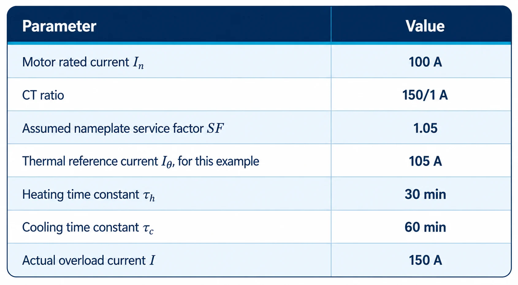
- For this example only, it is assumed that:
- The motor nameplate explicitly specifies a service factor of 1.05; and
- The protection relay defines \( I_\theta \) as the permissible continuous thermal current.
- Under these assumptions:
-
\[ I_\theta=I_n\times SF \]
This relationship is used only to demonstrate the calculation method. It is not a universal setting rule.
6.1 Thermal Reference Current
- The primary thermal reference current is:
\[ I_\theta = 100\times1.05 = 105\text{ A} \]
- With a CT ratio of 150/1 A, the corresponding relay secondary current is:
\[ I_{\theta,\mathrm{sec}} = \frac{105}{150} = 0.70\text{ A} \]
- Therefore, under the assumptions used in this example:
\[ I_{\theta,\mathrm{sec}}=0.70\text{ A} \]
- In practice, \( I_\theta \)should be determined from:
- Motor nameplate rated current;
- Permissible continuous loading;
- Service factor, if explicitly specified;
- Relay manufacturer’s definition of thermal reference current;
- Motor insulation class;
- Ambient temperature;
- Cooling method;
- Motor thermal-damage curves.
- A service factor should not be assumed for a motor whose nameplate or manufacturer documentation does not specify one.
- Some protection relays require the motor rated current to be entered directly and provide a separate overload-factor or service-factor setting. In such cases, the factor must not be applied twice.
6.2 Overload-Current Multiple
- If negative-sequence current is neglected in this example:
\[ I_{\mathrm{eq}}=I=150\text{ A} \]
Therefore:
\[ M = \frac{150}{105} = 1.429 \]
\[ M^2\approx2.041 \]
6.3 Cold-State Operating Time
- For a completely cold motor:
\[ H_0=0 \]
- Substituting the values into the cold-state equation:
\[ t_{\mathrm{cold}} = 30 \ln \left( \frac{2.041}{2.041-1} \right) \]
\[ t_{\mathrm{cold}} = 30 \ln \left( \frac{2.041}{1.041} \right) \]
\[ t_{\mathrm{cold}}\approx20.2\text{ min} \]
Therefore, if the motor starts from a completely cold state and continuously carries 150 A, the theoretical operating time is approximately:
\[ t_{\mathrm{cold}}\approx20.2\text{ min} \]
6.4 Operating Time at a 60% Initial Thermal State
- Assume that the current TCU is 60%:
\[ H_0=0.60 \]
- Substituting the values into the hot-state equation:
\[ t_{\mathrm{hot}} = 30 \ln \left( \frac{2.041-0.60}{2.041-1} \right) \]
\[ t_{\mathrm{hot}} = 30 \ln \left( \frac{1.441}{1.041} \right) \]
\[ t_{\mathrm{hot}}\approx9.7\text{ min} \]
- At the same overload current of 150 A:
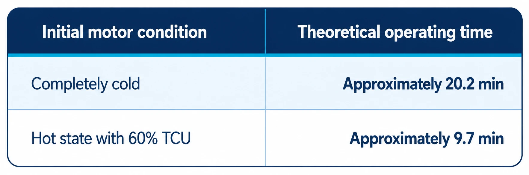
- This demonstrates how thermal memory reduces the permissible overload duration according to the thermal energy already accumulated in the motor.
7. Main Settings and Setting Principles
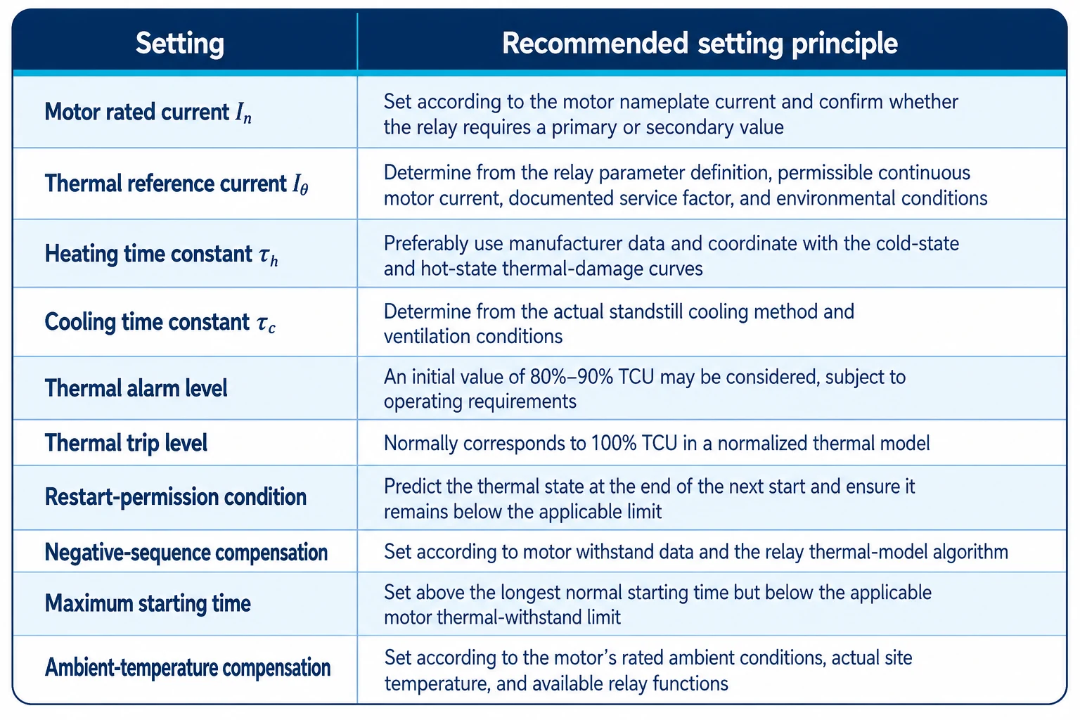
7.1 Restart-Permission Calculation
- Assume that:
- The thermal state before restarting is \( H_0 \);
- The equivalent thermal-current multiple during starting is \( M_{\mathrm{start}} \);
- The starting time is \( t_{\mathrm{start}} \).
- Under the simplified constant-current thermal model, the predicted thermal state at the end of the start is:
\[ H_{\mathrm{end}} = M_{\mathrm{start}}^2 – \left( M_{\mathrm{start}}^2-H_0 \right) e^{-t_{\mathrm{start}}/\tau_h} \]
- The basic restart-permission condition is:
\[ H_{\mathrm{end}}<1 \]
- When the thermal state is expressed as a percentage:
\[ \mathrm{TCU}_{\mathrm{end}}<100\% \]
- In practice, an engineering margin should be retained rather than allowing the predicted value to approach the trip threshold exactly.
- For a start from a completely cold state, where \( H_0=0 \), the thermal state at the end of the start is:
\[ H_{\mathrm{start}} = M_{\mathrm{start}}^2 \left( 1-e^{-t_{\mathrm{start}}/\tau_h} \right) \]
- This equation assumes that the equivalent starting current and thermal time constant remain constant throughout the starting period. Actual motor starting current normally varies as the motor accelerates. A more accurate calculation should therefore use the measured or manufacturer-provided starting-current profile, or the relay’s own integrated thermal-model calculation.
- A fixed restart-permission threshold, such as TCU below 30% or 40%, should not be applied without engineering verification. If the relay provides start thermal capacity, start inhibit, minimum time between starts, or starts-per-hour supervision, these settings should be coordinated with the motor’s permissible cold-start and hot-start capabilities.
8. Estimating the Heating Time Constant When Manufacturer Data Are Unavailable
- If the motor manufacturer does not provide a heating time constant, a preliminary value may be derived from the permissible cold locked-rotor time and locked-rotor current.
Define:
\[ M_{\mathrm{locked}} = \frac{I_{\mathrm{locked}}}{I_\theta} \]
- For a locked-rotor condition beginning from a completely cold state:
\[ t_{\mathrm{locked}} = \tau_h \ln \left( \frac{M_{\mathrm{locked}}^2} {M_{\mathrm{locked}}^2-1} \right) \]
Therefore:
\[ \tau_h = \frac{t_{\mathrm{locked}}} {\ln\left( \frac{M_{\mathrm{locked}}^2} {M_{\mathrm{locked}}^2-1} \right)} \]
where:
- \( t_{\mathrm{locked}} \) is the permissible cold locked-rotor time;
- \( I_{\mathrm{locked}} \)is the locked-rotor current;
- \( I_\theta \) is the thermal reference current;
- \( M_{\mathrm{locked}} \)is the locked-rotor current expressed as a multiple of the thermal reference current.
8.1 Calculation Example
Assume:
- Permissible cold locked-rotor time: \( t_{\mathrm{locked}}=10\text{ s} \);
Locked-rotor current: \( I_{\mathrm{locked}}=6I_n \);
Thermal reference current: \( I_\theta=I_n \).
Therefore:
\[ M_{\mathrm{locked}}=6 \]
\[ \tau_h = \frac{10} {\ln\left( \frac{6^2}{6^2-1} \right)} \]
\[ \tau_h = \frac{10} {\ln\left( \frac{36}{35} \right)} \]
\[ \tau_h\approx355\text{ s} \]
Converting to minutes:
\[ \tau_h = \frac{355}{60} \approx5.916\text{ min} \]
Rounded to one decimal place:
\[ \tau_h\approx5.9\text{ min} \]
- Depending on the relay setting resolution, 6.0 min may be used as a practical rounded value.
- This method only forces the simplified first-order thermal-model curve to pass through the selected cold locked-rotor point. It does not guarantee that the complete relay operating curve will match the entire motor thermal-damage curve.
After the preliminary calculation, the following coordination checks should be performed:
- The protection must not operate during the longest normal start;
- The protection must operate before the permissible cold locked-rotor time is exceeded;
- Hot locked-rotor or stall protection must operate within the applicable hot thermal-withstand limit;
- The relay operating curve should remain on the protective side of the motor thermal-damage curve;
- ANSI 49 should be coordinated with ANSI 48, ANSI 50, ANSI 51, and the applicable locked-rotor or stall protection.
9. Ambient-Temperature Compensation
- The thermal-overload capability of a motor is closely related to ambient temperature. Many motors are rated with reference to an ambient temperature of 40°C. However, 40°C is not a universal reference temperature mandated by ANSI 49 itself.
The following information should be confirmed for the actual application:
- The maximum ambient temperature stated on the motor nameplate;
- The motor manufacturer’s temperature-versus-load derating curve;
- Whether the protection relay supports ambient-temperature compensation;
- Whether ambient-temperature or RTD measurements are connected to the relay;
- The actual motor ventilation and cooling conditions.
- If the site ambient temperature exceeds the thermal model’s reference temperature and the relay does not provide the necessary compensation, the thermal model may underestimate the motor’s actual thermal state. This may delay protection operation and result in inadequate thermal protection.
- For high-temperature installations, the permissible continuous motor load should be reduced according to the manufacturer’s derating data, or the relay’s ambient-temperature compensation function should be enabled where available.
10. Coordination with Other Motor Protection Functions
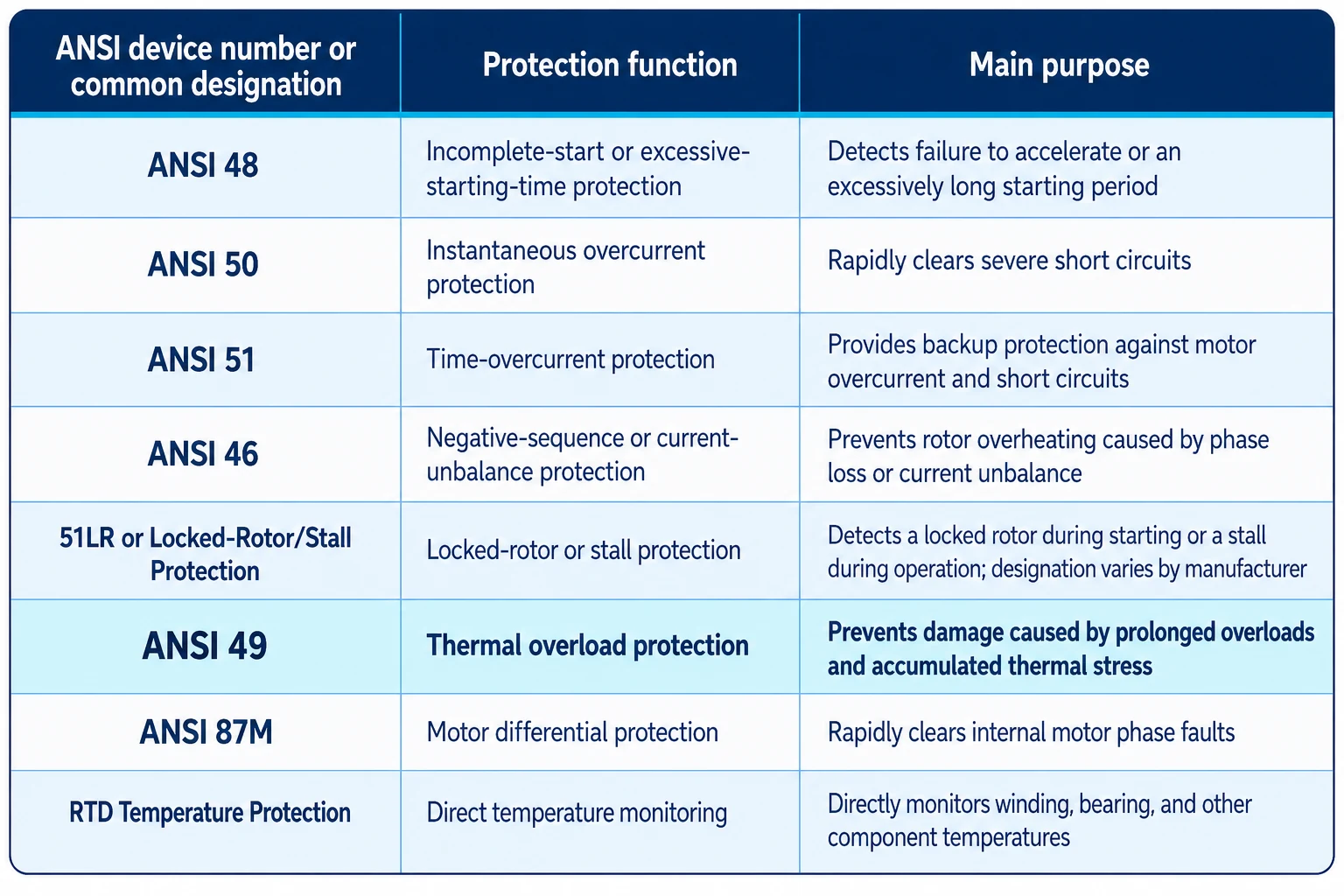
- The designation 51LR is widely used in motor-protection literature and relay documentation, but it is not a universally standardized standalone ANSI device number. Depending on the relay manufacturer, locked-rotor or stall protection may be implemented using ANSI 48 logic, supervised time-overcurrent elements, speed inputs, or manufacturer-specific logic.
- ANSI 14 specifically denotes an underspeed device. It should not automatically be treated as a universal designation for locked-rotor protection, although underspeed supervision may form part of a particular motor stall-protection scheme.
- ANSI 49 is a calculated thermal protection function based primarily on current, time, and cooling conditions. RTD temperature protection directly measures the temperature of motor windings, bearings, or other components.
- For large, high-voltage, or critical motors, thermal-model protection and RTD temperature monitoring should normally be used together. These functions complement each other and improve the reliability of motor thermal protection.
- ANSI 49 cannot completely replace direct RTD temperature measurement. RTDs may detect cooling-system failures, localized winding hot spots, abnormal bearing heating, and other temperature abnormalities that may not be adequately reflected by stator current.
11. Conclusion
- Motor thermal overload protection (ANSI 49) uses a motor thermal model to calculate motor heating, thermal accumulation, and cooling continuously. It is primarily intended to prevent thermal damage caused by:
- Prolonged overloads;
- Excessive mechanical loading;
- Excessive starting time;
- Locked-rotor or stall conditions;
- Frequent starts;
- Phase-loss operation;
- Three-phase current unbalance;
- Deteriorated cooling conditions;
- Excessive ambient temperature;
- Restarting before the motor has cooled sufficiently.
- Compared with conventional definite-time or inverse-time overcurrent protection, ANSI 49 can:
- Track accumulated thermal stress during motor operation;
- Retain the motor thermal state after shutdown;
- Distinguish between cold-state and hot-state overload capability;
- Simulate motor cooling after shutdown;
- Account for additional heating caused by negative-sequence current;
- Predict the thermal state at the end of the next start;
- Inhibit restarting when the remaining thermal capacity is insufficient;
- Coordinate more accurately with the motor’s thermal withstand capability.
- However, ANSI 49 cannot completely replace direct RTD monitoring of motor windings, bearings, and cooling-system-related temperature abnormalities. For large, high-voltage, or critical motors, the thermal model should be coordinated with RTD temperature monitoring, negative-sequence protection, locked-rotor or stall protection, and overcurrent protection.
Final settings should preferably be based on:
- The motor manufacturer’s thermal-damage curves;
- Permissible cold and hot locked-rotor times;
- Motor starting-current and acceleration characteristics;
- Permissible continuous loading;
- The specific thermal model implemented in the protection relay;
- Ambient temperature;
- Cooling method;
- Documented service factor, where applicable;
- Actual site loading and operating conditions.


