Automatic Bus Transfer vs High-Speed Bus Transfer: Differences, Principles and Selection
- Automatic bus transfer devices and high-speed bus transfer devices both transfer loads from a normal power source to an alternative source when the normal source fails or becomes abnormal. However, they differ significantly in their operating objectives, transfer criteria, operating speed, synchronism supervision and typical applications.
- In simple terms:
An automatic bus transfer device restores the power supply after the normal source is lost, whereas a high-speed bus transfer device aims to maintain continuity of supply by completing the transfer as quickly and safely as possible.
1. What Is an Automatic Bus Transfer Device?
An Automatic Bus Transfer device (ABT) automatically transfers a busbar from its normal source to an available alternative source when the normal source fails or no longer satisfies the permitted operating conditions.
Depending on the system configuration, it may also be described as an:
- Automatic bus transfer relay;
- Automatic transfer device;
- Automatic source transfer scheme;
- Bus-tie automatic transfer device;
- Automatic changeover device.
Typical arrangements include:
- Incomer-to-incomer automatic transfer;
- Bus-tie automatic transfer;
- Bus-section automatic transfer;
- Transformer automatic transfer;
- Main-to-standby source transfer;
- Two-source mutual standby operation.
Typical bus-tie automatic transfer sequence
Consider a system with two incomers, two bus sections and one normally open bus-tie circuit breaker:
- Incomer 1 supplies Bus Section I;
- Incomer 2 supplies Bus Section II;
- The bus-tie circuit breaker is normally open;
- One normal source fails;
- The ABT device confirms the source failure and busbar undervoltage;
- It verifies that the alternative source and healthy bus section are available;
- It trips the failed-source incomer circuit breaker;
- It confirms that the incomer circuit breaker is open;
- It closes the bus-tie circuit breaker;
- The healthy source then supplies both bus sections.
Automatic bus transfer devices normally use open-transition transfer, commonly described as a break-before-make sequence. The normal source must be disconnected before the alternative source is connected, unless the system has been specifically designed and approved for closed-transition transfer.
This prevents two independent sources from being connected in parallel without the necessary synchronism checks.
2. What Is a High-Speed Bus Transfer Device?
A High-Speed Bus Transfer device (HSBT) transfers a busbar from its normal source to an alternative source with the shortest practicable interruption.
In motor-intensive power systems, it may also be referred to as a Motor Bus Transfer (MBT) device, with Fast Bus Transfer and High-Speed Bus Transfer being common descriptors for transfer schemes designed to minimise interruption time.
The distinction is important:
- Motor Bus Transfer identifies the application—transferring a busbar that supplies running motors;
- Fast Transfer identifies a specific transfer method with no intentional delay;
- High-Speed Bus Transfer may describe either the overall device or a transfer scheme designed for rapid source transfer.
A high-speed bus transfer device is mainly used in:
- Power-station auxiliary power systems;
- Petrochemical plants;
- Refineries;
- Steelworks;
- Mining facilities;
- Cement plants;
- Pulp and paper mills;
- Other continuous-process industrial facilities.
These installations commonly have large numbers of medium-voltage motors. A prolonged power interruption may cause motors to slow down, contactors to drop out, process equipment to trip or an entire production process to shut down.
A high-speed bus transfer device therefore monitors more than the presence or absence of voltage. Depending on the system design, it may continuously measure or calculate:
- Normal-source voltage;
- Alternative-source voltage;
- Busbar voltage;
- Voltage-magnitude difference;
- Frequency difference;
- Phase-angle difference;
- Slip frequency;
- Rate of change of phase angle;
- Busbar residual voltage;
- Circuit-breaker opening and closing times.
The device determines whether a high-speed transfer can be completed within the permitted transfer window. If the fast-transfer conditions are no longer satisfied, it may proceed to in-phase, residual-voltage or fixed-time transfer.
3. Automatic Bus Transfer vs High-Speed Bus Transfer
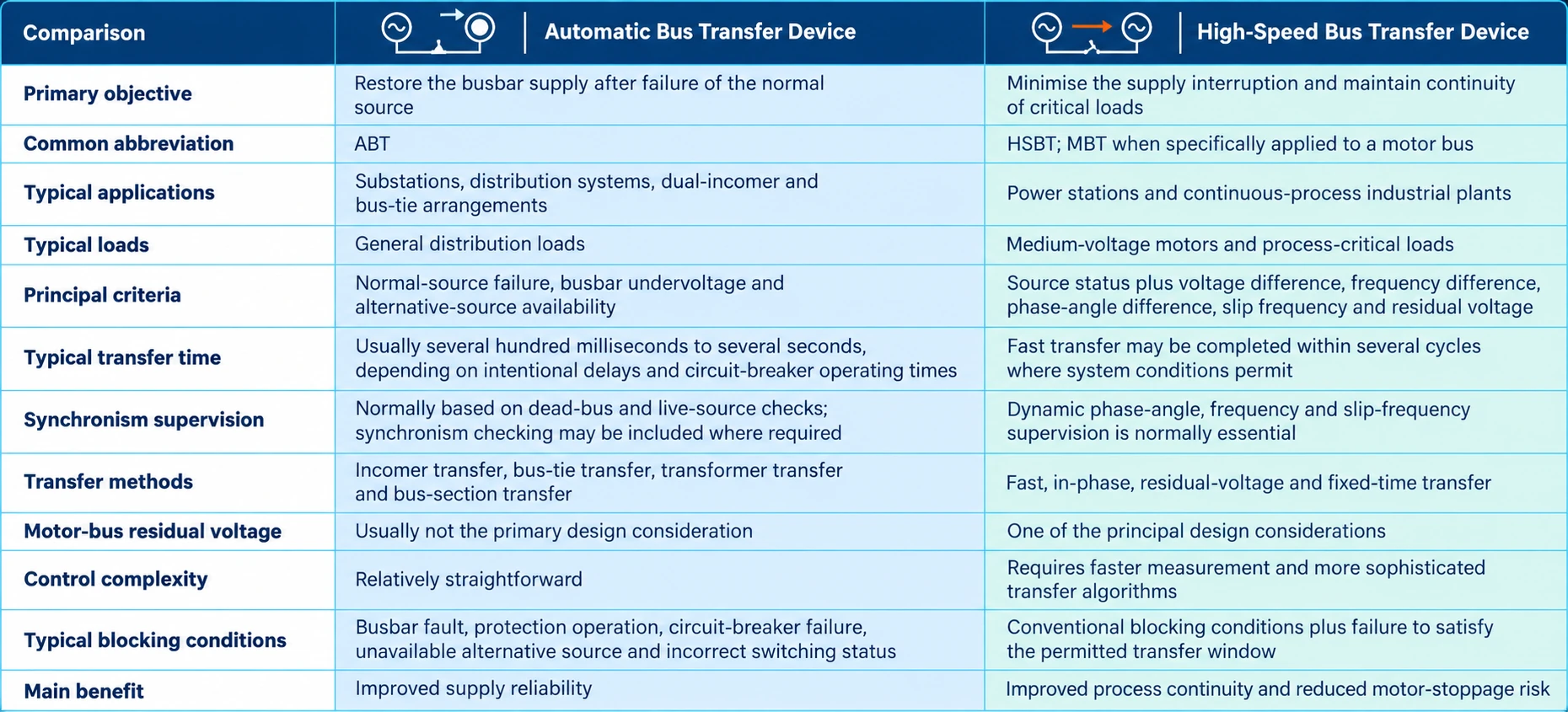
Transfer times are indicative only. Actual performance depends on the system configuration, initiation method, circuit-breaker operating times, motor-bus characteristics and device settings.
4. Why Does High-Speed Bus Transfer Require Phase-Angle and Frequency Supervision?
When a motor bus is disconnected from its normal source, the connected motors do not stop immediately. Their stored mechanical energy causes them to continue rotating and temporarily behave as generators.
The combined motor back electromotive force produces a decaying busbar voltage. During motor coast-down:
- The voltage magnitude decreases;
- The busbar frequency changes;
- The phase angle relative to the alternative source changes continuously;
- The slip frequency may increase;
- The permissible transfer window may be passed very quickly.
If the alternative source is connected when the phase-angle or frequency difference is excessive, the motors may be subjected to severe electrical and mechanical transients.
Possible consequences include:
- High transient current;
- Excessive electromagnetic torque;
- Mechanical stress on motors, couplings and driven equipment;
- A severe busbar-voltage dip;
- Circuit-breaker electrical stress;
- Protection operation;
- Motor stalling;
- Loss of the industrial process.
A high-speed bus transfer device must therefore be both fast and secure. Its purpose is not simply to close the alternative-source circuit breaker as quickly as possible, but to complete the transfer within an acceptable electrical transfer window.
5. High-Speed Bus Transfer Methods
5.1 Fast transfer
Fast transfer is initiated with no intentional delay when the voltage, frequency and phase-angle conditions are within their permitted limits.
Depending on the system design, the transfer may use either sequential or simultaneous operation.
Sequential transfer
In a Sequential Transfer, the alternative-source close command is issued only after the normal-source circuit breaker has been confirmed open.
This arrangement provides positive confirmation that the two sources will not be paralleled. However, its total transfer time includes the normal-source circuit-breaker opening time and the alternative-source circuit-breaker closing time.
Simultaneous transfer
In a Simultaneous Transfer, the normal-source opening command and alternative-source closing command are issued at approximately the same time.
It may also be described as a simultaneous-command transfer. The actual contact sequence depends on the opening and closing times of the two circuit breakers.
Simultaneous transfer can reduce the interruption time, but it requires:
- Accurately determined circuit-breaker operating times;
- Reliable open and close circuits;
- Suitable interlocking;
- Confirmation that unintended source paralleling cannot occur;
- Appropriate system and synchronism studies.
Fast transfer is normally the preferred method when its security criteria are satisfied because it minimises motor deceleration and disturbance to the industrial process.
5.2 In-phase transfer
If immediate fast-transfer conditions are not satisfied, the device may predict the movement of the motor-bus voltage relative to the alternative-source voltage.
The prediction normally considers:
- Present phase-angle difference;
- Slip frequency;
- Rate of change of slip;
- Alternative-source circuit-breaker closing time;
- Predicted phase angle at circuit-breaker contact closure.
The close command is issued in advance so that the circuit-breaker contacts close when the busbar and alternative-source voltages enter the permitted phase-angle window.
In-phase transfer is the commonly recognised international term for this transfer method.
5.3 Residual-voltage transfer
- If neither fast nor in-phase transfer is possible, the device may wait until the motor-bus residual voltage falls below a specified threshold before closing the alternative-source circuit breaker.
- Residual-voltage transfer takes longer and may not maintain motor continuity. However, waiting for the voltage to decay reduces the voltage difference across the alternative-source circuit breaker at closing.
- The residual-voltage threshold and associated time delay should be determined through a system and motor-bus transfer study.
5.4 Fixed-time transfer
- Fixed-time transfer closes the alternative source after a predetermined delay, provided all relevant permissive conditions are satisfied.
- This is normally a backup transfer method intended to restore supply after faster transfer methods have failed or become unavailable. It should not be assumed that motors will remain in operation throughout a fixed-time transfer.
- Fast, in-phase, residual-voltage and fixed-time methods are commonly offered within modern motor-bus transfer systems. Motor-bus transfer reference
6. Typical Automatic Bus Transfer Permissive Conditions
The exact logic depends on the single-line diagram and operating philosophy, but an automatic bus transfer device commonly requires the following permissive conditions:
- ABT function enabled;
- Normal-source failure detected;
- Affected busbar undervoltage detected;
- Alternative source available;
- Alternative-source voltage within limits;
- Alternative-source frequency within limits;
- Correct circuit-breaker positions;
- Normal-source circuit breaker confirmed open before alternative-source closing;
- Busbar protection not operated;
- No external blocking signal present;
- Circuit-breaker control circuits healthy;
- Stored-energy mechanism ready, where applicable;
- Selected operating mode consistent with the actual switchgear arrangement.
An automatic bus transfer device normally includes a single-operation feature. After completing one transfer attempt, the logic must reset or recharge before another automatic transfer can take place.
This prevents repeated transfers during an unresolved fault or unstable system condition.
7. Typical High-Speed Bus Transfer Permissive Conditions
In addition to conventional source and circuit-breaker checks, a high-speed bus transfer device may require:
- Normal-source failure or transfer initiation confirmed;
- Alternative source healthy and available;
- Busbar voltage measurement valid;
- Alternative-source voltage measurement valid;
- Voltage-magnitude difference within the permitted range;
- Phase-angle difference within the permitted range;
- Frequency difference within the permitted range;
- Slip frequency within the permitted range;
- Predicted phase angle at circuit-breaker contact closure acceptable;
- Normal-source circuit breaker opening sequence confirmed;
- Alternative-source circuit breaker ready to close;
- No protection or external blocking signal present;
- Correct transfer mode selected;
- Transfer window still available.
The applicable conditions depend on whether the device is performing fast, in-phase, residual-voltage or fixed-time transfer.
8. When Must Automatic or High-Speed Bus Transfer Be Blocked?
A transfer device must not energise a faulted busbar from an alternative source. Reliable blocking logic is therefore essential.
Typical blocking conditions include:
- Busbar protection operation;
- Transformer differential protection operation;
- Incomer, bus-tie or bus-section circuit-breaker failure;
- Alternative-source undervoltage;
- Alternative-source frequency outside the permitted range;
- Abnormal circuit-breaker position;
- Circuit-breaker control-circuit failure;
- Voltage-transformer circuit failure;
- Invalid voltage measurement;
- Manual trip, where required by the operating philosophy;
- Maintenance mode selected;
- External blocking input active;
- Transfer permissive conditions not satisfied;
- Synchronism or transfer-window criteria not satisfied;
- Internal device failure;
- Critical measurement failure.
Not every protection operation should produce the same transfer response. The blocking matrix must be based on the fault location, protection zone and primary system configuration.
For example, a fault within the busbar protection zone must block the transfer. By contrast, a disturbance upstream of the normal source may legitimately initiate transfer if the busbar and alternative source remain healthy.
9. Can an Automatic Bus Transfer Device Replace a High-Speed Bus Transfer Device?
In general, a conventional automatic bus transfer device cannot fully replace a high-speed bus transfer device.
An ABT device primarily evaluates:
- Normal-source status;
- Busbar voltage;
- Alternative-source availability;
- Circuit-breaker status;
- Protection and blocking inputs.
A high-speed bus transfer device must additionally evaluate the dynamic relationship between the motor-bus residual voltage and the alternative source.
For a conventional substation or distribution system supplying loads that can tolerate a short interruption, automatic bus transfer is normally sufficient.
For an industrial busbar supplying a large motor load, a conventional ABT device may introduce excessive delay. By the time the alternative source is connected, the motors may have slowed significantly or stopped. Closing without appropriate dynamic supervision may also expose the motors and driven equipment to unacceptable out-of-phase transfer stress.
A full-featured high-speed bus transfer device normally includes slower backup methods, such as residual-voltage or fixed-time transfer. It can therefore provide some of the supply-restoration functions associated with automatic bus transfer.
The relationship can be summarised as follows:
A high-speed bus transfer device may incorporate conventional automatic transfer functions, but a conventional automatic bus transfer device does not necessarily provide high-speed motor-bus transfer capability.
10. International Transfer Terminology
Automatic bus transfer, low-voltage automatic transfer switching equipment, motor bus transfer and static transfer systems should not be treated as interchangeable terms.
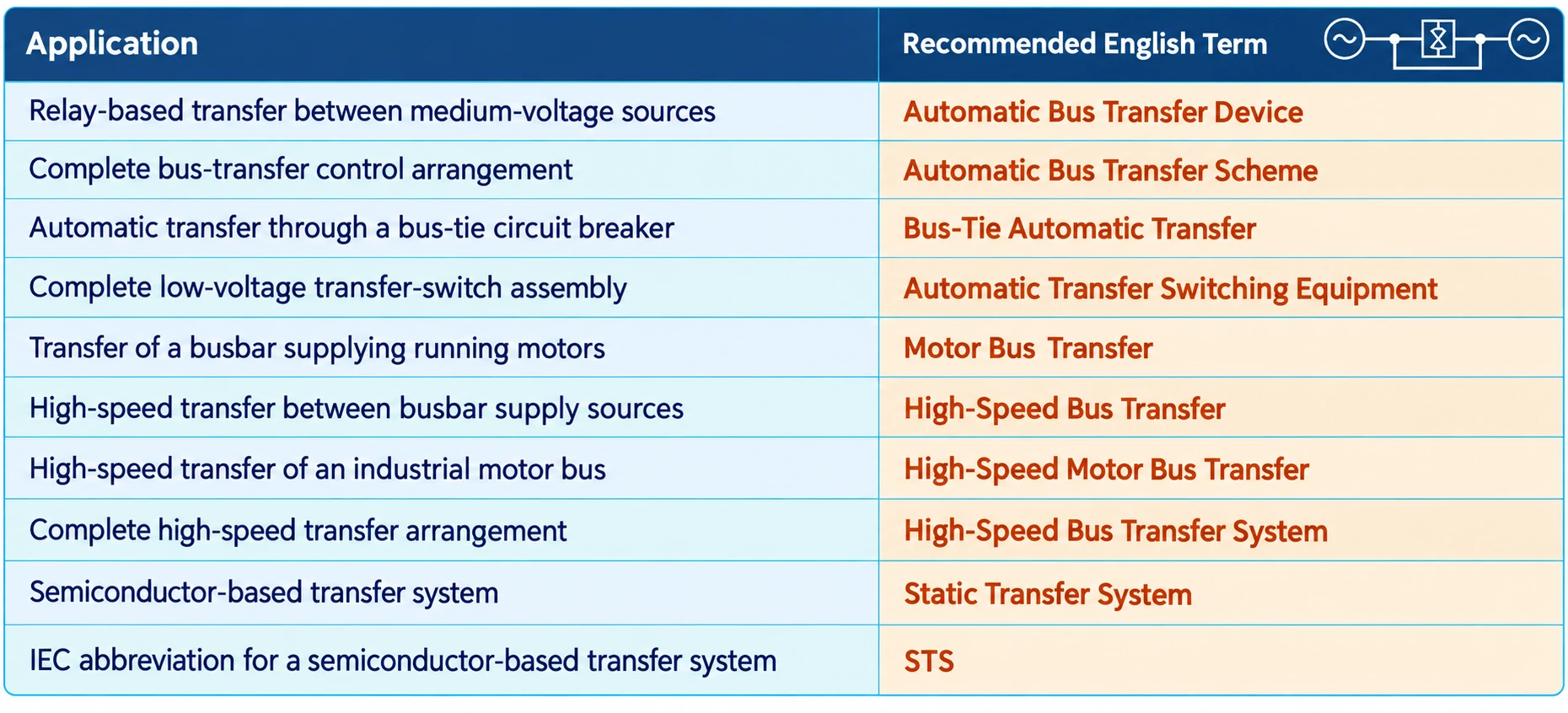 Automatic Transfer Switching Equipment
In low-voltage applications, Automatic Transfer Switching Equipment (ATSE) may combine source detection, transfer control and the switching mechanism in one complete assembly.
It is commonly used between:
- A utility source and a standby generator;
- Two utility sources;
- Two low-voltage transformers;
- A normal and an emergency power source.
IEC 60947-6-1 applies the terms Transfer Switching Equipment (TSE) and Automatic Transfer Switching Equipment (ATSE) to low-voltage transfer-switching equipment.
These terms should not automatically be applied to every medium-voltage relay-based bus-transfer device.
Static Transfer System
A Static Transfer System (STS) uses semiconductor switching devices to transfer a load between independent AC sources with a very short interruption.
Under the IEC 62310 series, the formal term is:
Static Transfer System (STS)
“Static Transfer Switch” is also widely used commercially, particularly when referring to the physical switching equipment. However, when citing the IEC standard or describing the complete system, Static Transfer System is the preferred term.
An STS should not be confused with an electromechanical automatic or high-speed bus transfer device. Their switching technologies, transfer times, voltage classes and typical applications are different.
11. How to Choose Between Automatic and High-Speed Bus Transfer
Choose an automatic bus transfer device when:
- Two substation incomers operate as mutual standby sources;
- A normally open bus-tie circuit breaker is installed between bus sections;
- The primary objective is automatic restoration of supply;
- The loads can tolerate a short interruption;
- The busbar does not supply a significant group of running medium-voltage motors;
- Dynamic motor-bus synchronism prediction is not required;
- Reliable interlocking and operating-mode adaptation are the main requirements.
Choose a high-speed bus transfer device when:
- The installation is a power station or continuous-process industrial plant;
- The busbar supplies a large number of medium-voltage motors;
- A short interruption may result in substantial production losses;
- Motor-bus residual-voltage behaviour must be considered;
- Dynamic phase-angle and slip-frequency supervision is required;
- Fast, in-phase, residual-voltage and fixed-time transfer methods are required;
- Reducing stress on motors, couplings and process equipment is a major objective.
A power-system and motor-bus transfer study should be completed when transfer performance is critical. Device speed alone cannot guarantee a successful transfer.
12. Information Required for System Selection
The following information should be provided when selecting or engineering an automatic or highspeed bus transfer device:
- Singleline diagram;
- Rated system voltage and frequency;
- Normal and alternative source arrangements;
- Incomer, bustie and bussection circuitbreaker configuration;
- Normal and alternative operating modes;
- Whether the sources may be paralleled;
- Circuitbreaker opening and closing times;
- Busbar load and load composition;
- Number and ratings of connected motors;
- Motor inertia constants and coastdown characteristics;
- Motor contactor or undervoltagerelease holdin times;
- Voltagetransformer ratios and connection arrangements;
- Currenttransformer ratios, where required;
- Protection trip and transferblocking requirements;
- Automatic retransfer requirements;
- SCADA and substation automation interfaces;
- Communication protocol requirements;
- Event records, disturbance records and timesynchronisation requirements.
These parameters are required to define the transfer sequence, permissive logic, blocking matrix, deadbus criteria and permissible transfer window.
13. GoWatron Automatic and High-Speed Bus Transfer Solutions
GoWatron provides dedicated transfer solutions for substation bus-tie applications, power-station auxiliary systems and critical industrial motor buses.
GWPR300-ABT-B Bus-Tie Automatic Transfer Relay
The GWPR300-ABT-B Bus-Tie Automatic Transfer Relay is designed for dual-incomer and sectionalised-busbar systems.
It supports:
- Normal-source supervision;
- Alternative-source permissive checks;
- Bus-tie circuit-breaker control;
- Multiple bus-tie transfer modes;
- Transfer blocking and interlocking;
- Local and remote control;
- Event recording;
- Integration with SCADA and substation automation systems.
The GWPR300-ABT-B focuses on reliable restoration of supply following a normal-source failure.
GWPR350-HSBT High-Speed Busbar Transfer Device
The GWPR350-HSBT High-Speed Busbar Transfer Device is designed for high-speed source transfer in power-station auxiliary systems and critical industrial power networks.
It is suitable for applications requiring:
- High-speed source transfer;
- Normal and alternative source supervision;
- Busbar voltage supervision;
- Phase-angle difference supervision;
- Frequency and slip-frequency supervision;
- Motor-bus residual-voltage evaluation;
- Fast and secure circuit-breaker transfer control;
- Coordinated transfer between normal and alternative sources.
The GWPR350-HSBT focuses on minimising supply interruption and maintaining the continuity of critical motor and process loads.
Product selection summary
| Product | Device Type | Principal Application |
| GWPR300-ABT-B | Bus-Tie Automatic Transfer Relay | Substation incomer and bus-tie automatic transfer |
| GWPR350-HSBT | High-Speed Busbar Transfer Device | Power-station auxiliary systems and industrial motor-bus transfer |
The GWPR300-ABT-B is an automatic bus transfer relay, whereas the GWPR350-HSBT is a high-speed busbar transfer device.
14. Conclusion
Automatic bus transfer and high-speed bus transfer devices both transfer a busbar from one source to another, but they should not be distinguished solely by operating time.
An automatic bus transfer device focuses on:
- Detecting normal-source failure;
- Verifying alternative-source availability;
- Applying the specified switching sequence;
- Restoring the busbar supply safely and reliably.
A high-speed bus transfer device focuses on:
- Continuously evaluating the dynamic motor-bus condition;
- Measuring voltage, frequency and phase-angle differences;
- Monitoring slip frequency and busbar residual voltage;
- Predicting an acceptable circuit-breaker closing instant;
- Maintaining motor and process continuity wherever possible.
Therefore:
Automatic bus transfer is generally suitable for substation incomer and bus-tie applications, whereas high-speed bus transfer is normally preferred for power-station auxiliary systems and industrial motor buses supplying process-critical loads.


