Motor Phase-Loss Protection Relay: Operating Principle, Functions and Setting Calculations
Motor phase loss, also known as open-phase operation or single phasing, occurs when one phase of a three-phase power supply or one phase current is interrupted. A three-phase motor may fail to start if phase loss is present before starting. If phase loss occurs while the motor is running, the motor may continue to rotate, but the currents in the two remaining phases usually increase significantly. A substantial negative-sequence current is also produced, causing rapid heating of both the stator and rotor.
A motor phase-loss protection relay detects phase-loss conditions by monitoring the three-phase voltages, phase currents, current unbalance or negative-sequence current. After the configured operating delay, the relay trips the contactor or circuit breaker to prevent thermal damage to the motor.
Phase-loss protection is commonly implemented using the following ANSI functions:
- ANSI 46: Negative-sequence/current-unbalance protection
- ANSI 37: Undercurrent protection, which may be used as a supplementary phase-loss criterion
ANSI 46 and ANSI 37 can both contribute to phase-loss protection. Phase-loss protection itself does not normally have a separate, universally recognised ANSI device number.
1. Common Causes of Motor Phase Loss
A phase-loss fault may originate in the power supply, switching equipment, feeder circuit or motor itself. Common causes include:
- Operation of one phase fuse;
- Burnt, damaged or poorly conducting contactor main contacts;
- Failure of one circuit-breaker pole to close correctly;
- An open conductor in the motor cable;
- A loose or disconnected terminal;
- An open circuit in one motor winding;
- Failure to connect one phase during installation or maintenance;
- An open-phase fault in the upstream supply circuit.
Depending on when the fault occurs, phase loss can be divided into pre-start phase loss and running phase loss.
1.1 Pre-start Phase Loss
If one phase is already absent before the motor is started, the motor will normally fail to accelerate and may remain stalled. The two energised phases may continue to carry high starting current, causing the motor temperature to rise rapidly.
1.2 Phase Loss During Running
If phase loss occurs during normal operation, the motor may continue to rotate because of its inertia and the remaining electromagnetic torque. However, it will normally exhibit:
- Reduced output torque;
- Increased slip;
- Increased vibration and noise;
- Higher currents in the two remaining phases;
- Severe three-phase current unbalance;
- Increased negative-sequence current;
- Rapid stator and rotor heating.
At full load or under heavy-load conditions, the currents in the two remaining phases may rise to approximately 1.5–2 times their previous normal values. The actual current depends on the motor loading, supply voltage, winding connection and mechanical load characteristics. This range must not be used as a fixed protection-setting basis.
2. Operating Principles of Motor Phase-Loss Protection
Depending on the measured quantities and protection algorithm, motor phase-loss protection can be divided into voltage-based, current-based, current-unbalance and negative-sequence current methods.
2.1 Voltage-Based Phase-Loss Protection
A voltage-based relay monitors the three-phase supply voltages. If one phase voltage disappears or the three-phase voltages become severely unbalanced, the relay identifies a possible supply phase-loss condition and issues an alarm or trip command.
Common operating criteria include:
- One phase voltage falling below the set value;
- Three-phase voltage unbalance exceeding the set value;
- Zero-sequence voltage exceeding the set value;
- Significant voltage displacement at an artificial neutral point.
When phase loss occurs upstream of the voltage measurement point and the motor has not yet started, the disconnected phase voltage will normally fall significantly. A voltage-based relay can therefore detect the fault relatively quickly.
However, voltage-based protection has several limitations:
- A phase loss downstream of the voltage measurement point may not be detected;
- If phase loss occurs while the motor is running, the remaining phases may produce an induced or regenerated voltage in the disconnected phase through the motor windings;
- A measurable voltage may remain on the disconnected phase, reducing the sensitivity of the undervoltage or phase-loss criterion;
- It may not reliably detect phase loss in downstream contactor contacts, motor cables or internal motor windings.
The principal risk of failure to operate therefore arises when phase loss occurs while the motor is running or when the open circuit is downstream of the voltage measurement point. Important motors should not rely exclusively on voltage-based phase-loss protection.
2.2 Current-Based Phase-Loss Protection
A current-based relay monitors the three phase currents through current transformers or internal current sensors. If one phase current becomes substantially lower than the other two, the relay identifies a possible phase-loss condition.
Following an actual phase interruption, the measured current in the open phase may not be exactly zero. Measurement-channel noise, leakage current, induced components, CT errors and signal-processing methods may produce a small non-zero reading.
Practical protection therefore checks whether one phase current has fallen significantly below the other two or below a defined phase-loss low-current threshold, rather than requiring it to be exactly zero.
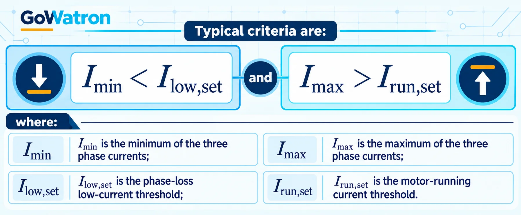
This combined logic prevents a phase-loss indication when the motor is normally stopped and all three phase currents are zero.
Current-based protection can normally detect:
- Operation of one phase fuse;
- An open contactor main contact;
- An open conductor in the motor cable;
- A disconnected terminal;
- Some types of open circuit in the motor windings.
For motors that operate continuously at light load, a fixed undercurrent threshold alone may not provide both adequate sensitivity and security. Independent current-unbalance or negative-sequence protection should therefore also be applied.
2.3 Current-Unbalance Phase-Loss Protection
Under normal operating conditions, the three phase currents are approximately balanced. When phase loss occurs, one phase current falls significantly, the other two phase currents change, and the current unbalance increases sharply.
Different relays may use different definitions of current unbalance.
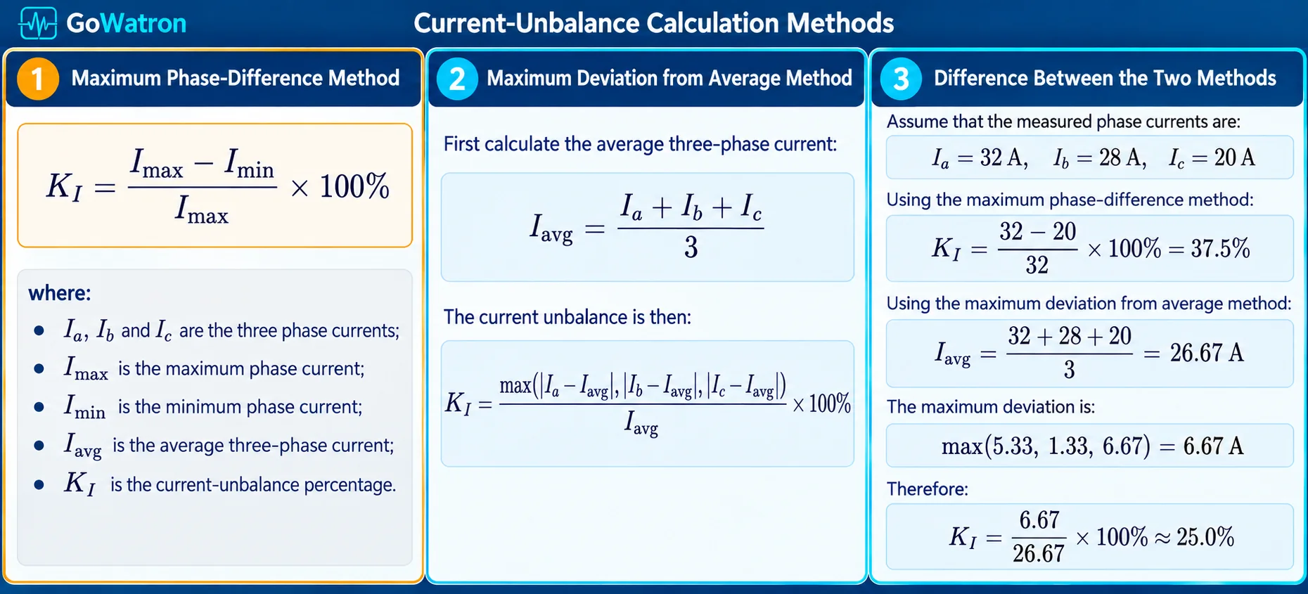
| Calculation method | Current unbalance |
| Maximum phase-difference method | 37.5% |
| Maximum deviation from average method | 25.0% |
If the protection pickup is set to 30%, the maximum phase-difference method will operate, whereas the maximum deviation from average method will not.
The calculation method used by the relay must therefore be confirmed before settings are applied. Current-unbalance settings based on different calculation methods are not interchangeable.
2.4 Negative-Sequence Current Phase-Loss Protection
A numerical motor protection relay normally calculates the positive-sequence current \( 𝐼1 \)and negative-sequence current \( 𝐼2 \)
from the three measured phase currents.
During normal balanced operation, negative-sequence current is low. Phase loss causes severe current asymmetry and a significant increase in negative-sequence current.
Negative-sequence current produces a reverse-rotating magnetic field. This field induces additional rotor currents and losses. Consequently, the rotor may overheat even when the average phase current does not substantially exceed the rated motor current.
ANSI 46 negative-sequence/current-unbalance protection is therefore one of the principal methods used to protect important motors against phase loss.
3. Functions of a Motor Phase-Loss Protection Relay
3.1 Prevention of Stator-Winding Damage
Following phase loss during operation, the currents in the two remaining phases may increase significantly. If the protection does not operate promptly, the stator-winding temperature can rise rapidly, causing insulation ageing, phase-to-phase faults or complete winding failure.
3.2 Prevention of Rotor Overheating
The negative-sequence current produced by phase loss creates a reverse-rotating magnetic field and additional rotor losses. Conventional overload protection mainly responds to the motor’s overall thermal condition and may not adequately represent negative-sequence rotor heating.
3.3 Prevention of Open-Phase Starting and Prolonged Stalling
A motor with a missing phase before starting will normally fail to accelerate and may remain stalled. Phase-loss protection can disconnect the supply before sustained starting current causes severe thermal damage.
3.4 Detection of Main-Circuit Open Conductors
Three-phase current measurement can detect phase interruptions caused by contactor contacts, feeder cables, terminals and some internal motor-winding faults.
3.5 Reduction of Equipment Damage and Downtime
Prompt removal of a phase-loss fault prevents the condition from developing into winding failure or insulation breakdown, reducing repair costs and unplanned production downtime.
4. Motor Rated-Current Calculation
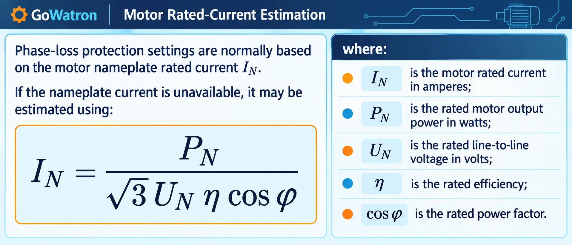
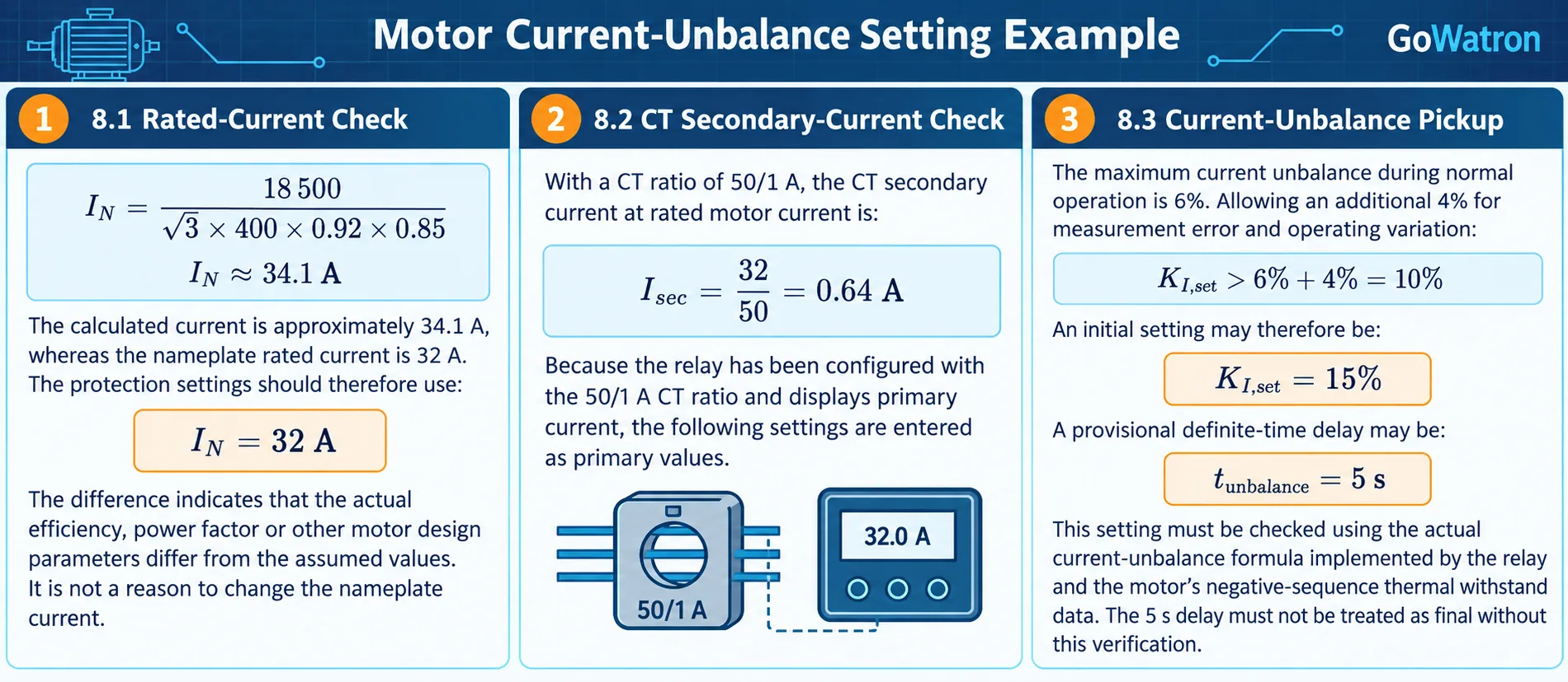
This formula should only be used for an initial estimate. Protection settings should use the motor nameplate rated current wherever available.
If the calculated current differs from the nameplate current, the actual efficiency, power factor or other design parameters may differ from the assumed values. The calculated result must not be used to alter or replace the nameplate rating.
5. Motor Phase-Loss Protection Setting Philosophy
Numerical motor protection relays often implement ANSI 46 in two stages:
- High-set definite-time stage: Provides rapid tripping for complete phase loss or severe current unbalance.
- Low-set thermal or inverse-time stage: Protects the motor against lower but sustained negative-sequence current and current unbalance.
The exact implementation varies between relay manufacturers. Some relays provide separate phase-loss, current-unbalance and negative-sequence elements, while others integrate these functions within one or more ANSI 46 stages.
The settings should distinguish between:
- Complete phase loss requiring rapid operation;
- Severe current unbalance that does not satisfy the complete phase-loss low-current logic;
- Lower but sustained negative-sequence current requiring thermal or inverse-time protection.
The following settings may be required:
- Motor rated current;
- Current-unbalance pickup;
- Negative-sequence current pickup;
- Negative-to-positive-sequence current ratio;
- Minimum positive-sequence current threshold;
- Phase-loss low-current threshold;
- Motor-running current threshold;
- High-set current-unbalance or negative-sequence threshold;
- Complete phase-loss operating delay;
- Severe current-unbalance operating delay;
- Negative-sequence inverse-time characteristic;
- Starting-blocking time.
5.1 Current-Unbalance Pickup
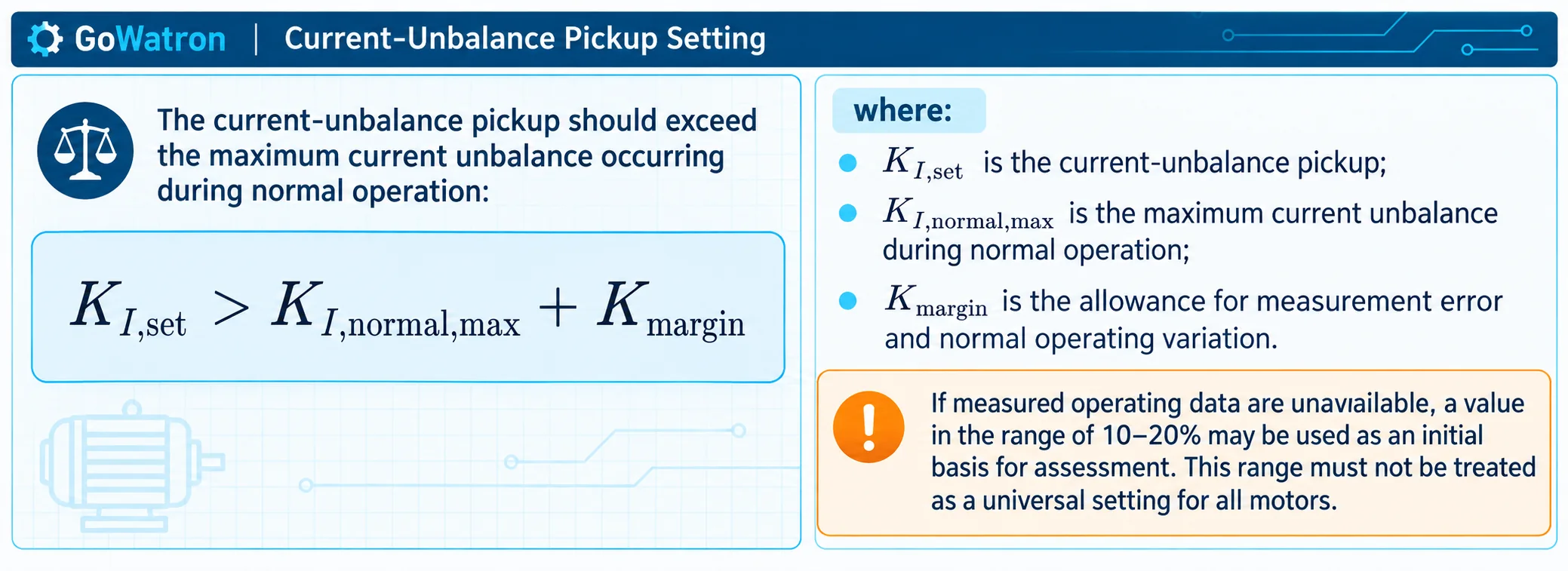
- Normal differences between the three phase currents;
- Long-term supply unbalance;
- Motor load variation;
- CT and relay measurement errors;
- The current-unbalance algorithm implemented by the relay;
- The motor’s negative-sequence thermal withstand capability.
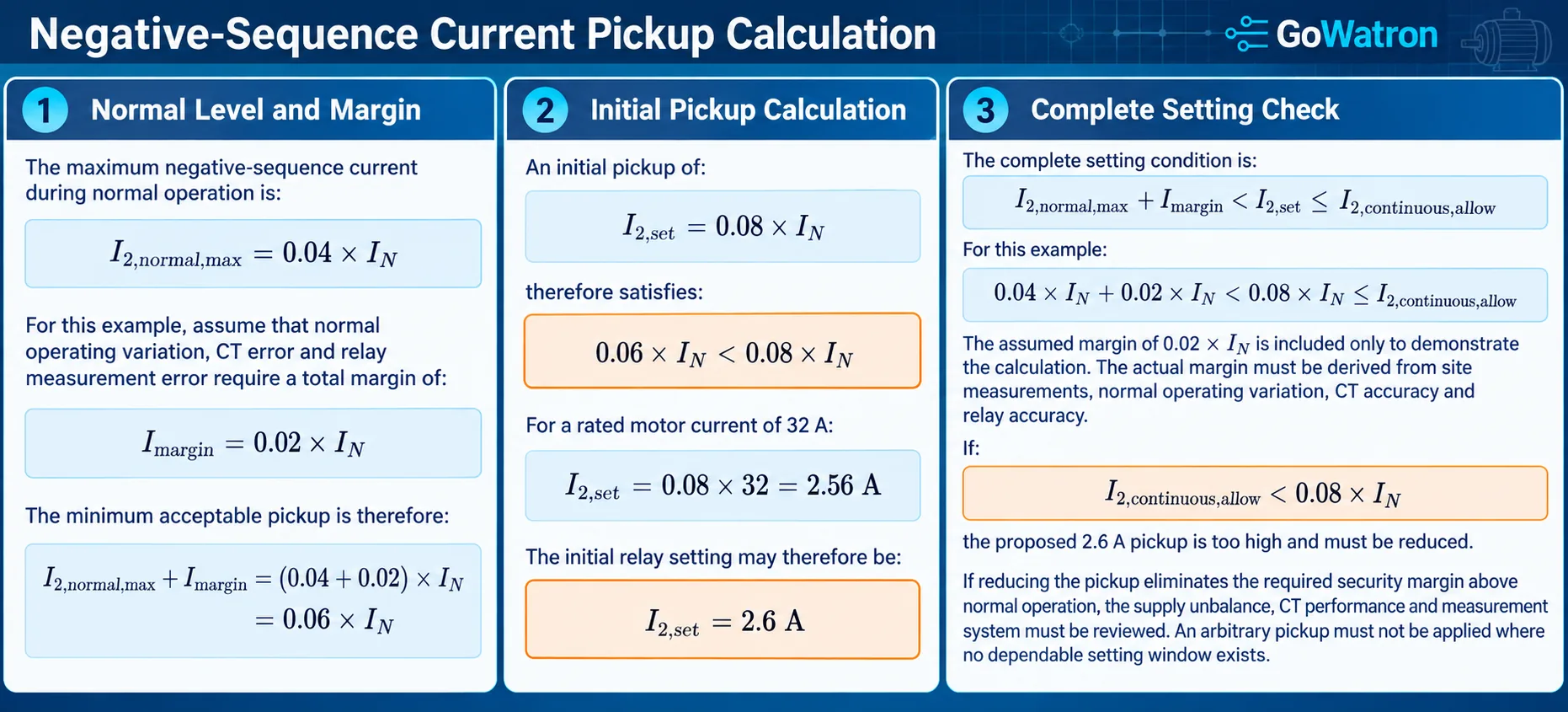
5.2 Negative-Sequence Current Pickup
The absolute negative-sequence current criterion is:
\[ I_2>I_{2,\mathrm{set}} \]
\[ I_{2,\mathrm{normal,max}}+I_{\mathrm{margin}} < I_{2,\mathrm{set}} \leq I_{2,\mathrm{continuous,allow}} \]
- \( I_{2,\mathrm{normal,max}} \)is the maximum negative-sequence current measured during normal operation;
- \( I_{\mathrm{margin}} \)is the allowance for normal operating variation, supply unbalance, CT error and relay measurement error;
- \( I_{2,\mathrm{continuous,allow}} \)is the motor manufacturer’s permissible continuous negative-sequence current.
\[ I_{\mathrm{margin}} \geq I_{2,\mathrm{variation}} + I_{\mathrm{CT,error}} + I_{\mathrm{relay,error}} \]
The algebraic sum provides a conservative estimate because it assumes that all error components act in the same direction at the same time. Where a more precise assessment is required, the errors should be combined according to their characteristics. Independent random errors may be combined using a root-sum-square method, whereas known systematic errors and bias components should be treated separately or added algebraically.
If:
\[ I_{2,\mathrm{normal,max}}+I_{\mathrm{margin}} \geq I_{2,\mathrm{continuous,allow}} \]
Where manufacturer data are unavailable, the following range may be used only as an initial engineering reference:
\[ I_{2,\mathrm{set}} = (0.05~0.10)\times I_N \]
This range is not a universal permissible continuous negative-sequence current for all motors.
For relays with separate alarm and trip stages:
- The alarm pickup may be set near the permissible continuous negative-sequence current;
- The trip element should use a definite-time or inverse-time characteristic that remains within the motor’s negative-sequence thermal withstand curve.
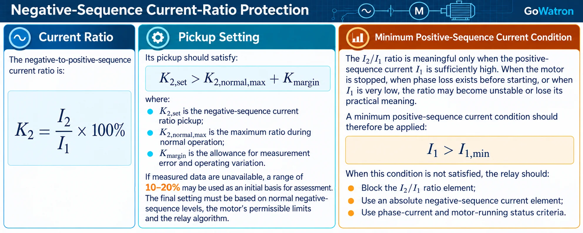
5.3 Negative-to-Positive-Sequence Current Ratio
5.4 Negative-Sequence Inverse-Time Protection
For important motors, negative-sequence inverse-time protection should be co-ordinated with the rotor negative-sequence thermal withstand characteristic.
A simplified thermal relationship may be expressed as:
\[ \left(\frac{I_2}{I_N}\right)^2t=K \]
or:
\[ t= \frac{K} {\left(I_2/I_N\right)^2} \]
where:
- \( t \) is the permissible duration of the negative-sequence current;
- \( I_2/I_N \) is the negative-sequence current in per-unit form;
- \( K \) is the motor negative-sequence withstand constant.
This equation is only a simplified representation. Actual relays may use different inverse-time equations, minimum operating levels, time multipliers, thermal-memory functions and reset characteristics.
The inverse-time characteristic should remain below the motor manufacturer’s negative-sequence withstand curve across the applicable current range:
\[ t_{\mathrm{relay}}(I_2) < t_{\mathrm{motor,allow}}(I_2) \]
with an appropriate engineering margin.
Where two ANSI 46 stages are available, a typical arrangement is:
- ANSI 46 high-set stage: Definite-time operation for severe current unbalance or complete phase loss;
- ANSI 46 low-set stage: Inverse-time operation for lower but sustained negative-sequence current.
The actual stage designations and operating characteristics must be confirmed from the relay manual.
5.5 Phase-Loss Low-Current Threshold
The complete phase-loss criterion may use:
\[ I_{\min}<I_{\mathrm{low,set}} \]
This setting should be based principally on the minimum current expected during normal motor operation:
\[ I_{\mathrm{low,set}}< I_{\mathrm{normal,min}} \]
where\( I_{\mathrm{normal,min}} \)is the minimum normal operating current under all permitted operating conditions.
The phase-loss low-current threshold should:
- Be below the minimum normal operating current with an adequate measurement margin;
- Be above any residual current that may be measured in an open phase;
- Distinguish normal light-load operation from complete phase interruption;
- Be combined with motor-running current, current-unbalance or negative-sequence criteria.
This low-current criterion is intended principally for complete or near-complete phase loss. It does not provide complete coverage for partial phase loss or other asymmetrical conditions.
5.6 Complete Phase-Loss and General Unbalance Logic
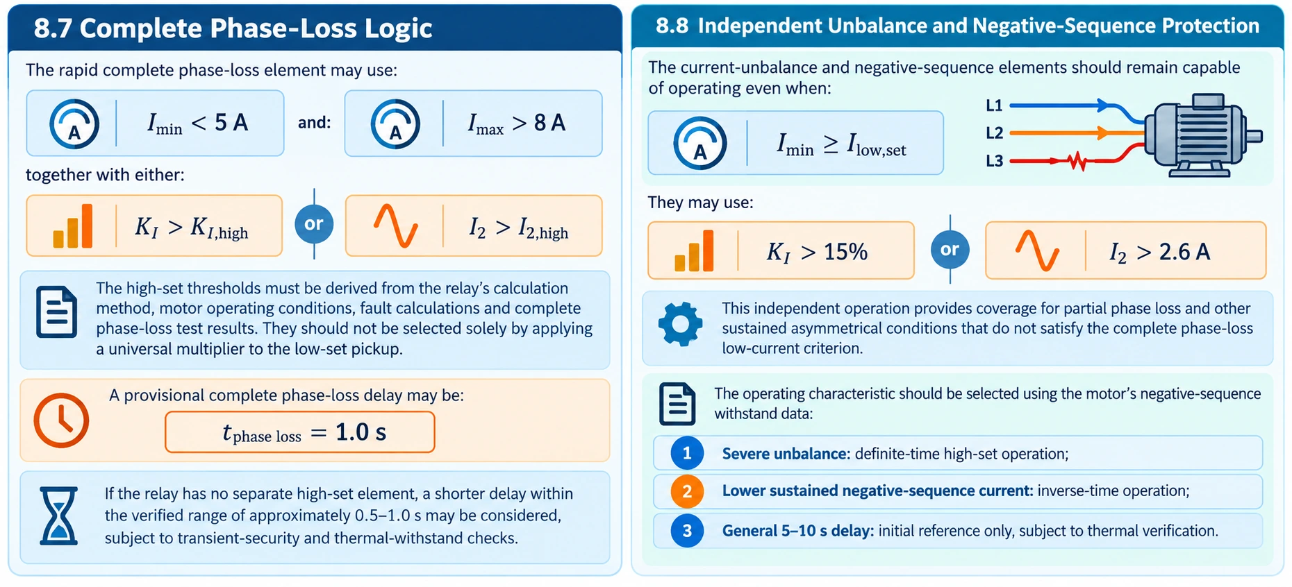
The complete phase-loss element may use the following combined logic:
\[ I_{\min}<I_{\mathrm{low,set}} \]
and:
\[ I_{\max}>I_{\mathrm{run,set}} \]
together with either:
\[ K_I>K_{I,\mathrm{high}} \]
or:
\[ I_2>I_{2,\mathrm{high}} \]
This element provides rapid operation when one phase current has fallen to a very low level while meaningful current remains in the other phases.
High-Set Current-Unbalance Threshold
The high-set current-unbalance threshold should satisfy:
\[ K_{I,\mathrm{high}}>K_{I,\mathrm{set}} \]
It should be:
Higher than the maximum unbalance expected during starting, switching and normal operation;
Lower than the current unbalance reliably produced by complete phase loss;
- Verified using the exact current-unbalance algorithm implemented by the relay;
- Confirmed through secondary-injection testing.
A value such as 50–70% may be considered only as an initial reference where the relay algorithm and fault studies support it. It must not be treated as a universal setting.
For example, if the relay uses:
\[ K_I= \frac{I_{\max}-I_{\min}} {I_{\max}}\times100\% \]
a complete phase loss with \( I_{\min} \)approaching zero produces a calculated current unbalance approaching 100%. The selected high-set value should provide adequate margin below this expected fault value while remaining above non-fault unbalance.
\[ I_{2,\mathrm{high}}>I_{2,\mathrm{set}} \]
It should be selected so that:
- It remains secure during motor starting and normal operating transients;
- It operates for severe asymmetry or complete phase loss;
- Its operating time remains within the motor’s negative-sequence thermal withstand capability;
- It is supported by fault calculations or secondary-injection test results.
Relays Without a Separate High-Set ANSI 46 Stage
If the relay does not provide a separate high-set ANSI 46 stage, the complete phase-loss logic may use:
- The phase-loss low-current criterion;
- The motor-running current criterion;
- The normal current-unbalance or negative-sequence pickup as a confirming condition.
The complete phase-loss operating delay may then be selected towards the shorter end of the applicable range, for example approximately 0.5–1.0 s, but only after confirming:
- Security against starting transients;
- Security during contactor switching and supply transfer;
- Relay filtering and measurement time;
- The motor’s phase-loss and negative-sequence thermal withstand capability;
- Correct operation through secondary-injection testing.
A shorter delay improves operating speed but does not increase the measuring sensitivity of the protection element. It must not be used as a substitute for an inadequate pickup setting.
Independent Unbalance and Negative-Sequence Operation
The general current-unbalance and negative-sequence elements should operate independently of the complete phase-loss low-current condition:
\[ K_I>K_{I,\mathrm{set}} \]
or:
\[ I_2>I_{2,\mathrm{set}} \]
This independent operation provides protection against:
- Partial phase loss;
- High-resistance contactor contacts;
- Loose or oxidised connections;
- Severe phase-current asymmetry where \( I_{\min} \) remains above \( I_{\mathrm{low,set}} \);
- Other sustained negative-sequence current conditions.
The protection can therefore be divided into two levels:
| Protection level | Principal criteria | Primary purpose |
| Complete phase-loss protection | Low phase current + motor-running current + severe unbalance or negative sequence | Rapid removal of complete or near-complete phase loss |
| Independent ANSI 46 protection | Current-unbalance or negative-sequence pickup | Protection against partial phase loss and sustained asymmetry |
5.7 Motor-Running Current Threshold
\[ I_{\max}>I_{\mathrm{run,set}} \]
The threshold should normally satisfy:
\[ I_{\mathrm{low,set}} < I_{\mathrm{run,set}} < I_{\mathrm{normal,min}} \]
The motor-running current threshold should therefore:
- Be below the minimum normal operating current;
- Include an adequate margin for load and measurement variations;
- Be higher than the phase-loss low-current threshold;
- Confirm that meaningful current remains in the motor circuit.
5.8 Complete Phase-Loss Operating Time
\[ t_{\mathrm{phase\ loss}}=0.5~1.0\text{ s} \]
The final delay should consider:
- Motor thermal capability;
- Contactor transfer and switching transients;
- Relay filtering and measurement time;
- The required security against transient current disturbances.
5.9 Current-Unbalance Operating Time
A delay of 5–10 s may be used only as an initial reference for a general current-unbalance definite-time element:
\[ t_{\mathrm{unbalance}}=5~10\text{ s} \]
It is not a universal setting.
The final operating time must be checked against the motor’s negative-sequence thermal withstand data:
\[ t_{\mathrm{unbalance}} < t_{\mathrm{motor,allow}}(I_2) \]
with an appropriate engineering margin.
If the manufacturer’s data show that the permissible duration at a particular negative-sequence current is shorter than the proposed relay delay, the relay delay must be reduced or a suitable inverse-time characteristic must be applied.
If the permissible duration is substantially longer, a 5 s setting may be unnecessarily conservative and could cause avoidable trips. A longer delay or inverse-time characteristic may then provide better co-ordination.
The setting must balance:
- Protection of the rotor against negative-sequence heating;
- Security against temporary supply or load unbalance;
- Process continuity requirements;
- Relay and CT measurement performance.
Increasing the pickup value is not a substitute for shortening an operating delay that exceeds the motor’s thermal withstand time.
5.10 Starting-Blocking Time
Transient current unbalance may occur while a motor is starting. Some relays therefore block the general current-unbalance element or modify its settings during starting.
The blocking time should satisfy:
\[ t_{\mathrm{block}}> t_{\mathrm{start,max}} \]
where:
- \( t_{\mathrm{block}} \)is the starting-blocking time;
- \( t_{\mathrm{start,max}} \)is the longest actual starting time under the most onerous operating conditions.
The following points should be considered:
- The blocking time should not be unnecessarily long, as this increases the protection blind period during starting;
- Heavy-load starting, reduced-voltage starting, soft starting and high-inertia loads may require substantially longer starting times;
- The setting should be based on the longest actual starting time under the most onerous conditions;
- A complete phase-loss high-set element should preferably remain in service during starting;
- The general current-unbalance element may be temporarily blocked, assigned a higher pickup or given a longer delay;
- The relay’s actual starting logic must be confirmed.
Some relays block all phase-loss and current-unbalance functions during starting. If phase loss occurs during this period, tripping may be delayed until the blocking time expires.
The following must therefore be confirmed:
- Which functions are blocked during starting;
- Whether complete phase-loss protection remains enabled;
- Whether fault evaluation starts immediately when the blocking period expires;
- Whether open-phase starting or failed-start protection is provided;
- Whether completion of starting is determined by current, time, speed or contactor status.
6. Effect of CT Ratio and Connection on Protection Settings
Where external CTs are used, the following must be confirmed before settings are calculated:
– CT primary rated current;
– Whether the CT secondary rating is 1 A or 5 A;
– Whether relay measurements and settings are expressed as primary or secondary values;
– Correct assignment of the phase CTs to the relay’s A-, B- and C-phase inputs;
– CT polarity;
– Phase sequence;
– CT connection arrangement;
– CT ratio configured in the relay;
– CT rated burden, accuracy class and saturation performance;
– Absence of open circuits, short circuits or poor connections in the CT secondary circuit.
The CT ratio is:
\[ K_{\mathrm{CT}}= \frac{I_{\mathrm{CT,pri}}} {I_{\mathrm{CT,sec}}} \]
The relationship between primary and secondary current is:
\[ I_{\mathrm{pri}}= K_{\mathrm{CT}}\times I_{\mathrm{sec}} \]
For example, with a CT ratio of 100/1 A and a motor primary current of 32 A:
\[ I_{\mathrm{sec}}= \frac{32}{100} =0.32\text{ A} \]
If relay settings are entered as secondary values, all current thresholds must be converted to the CT secondary side. If the CT ratio has been correctly entered and the relay displays primary current, settings can normally be entered directly as primary values.
Incorrect CT polarity or phase sequence can produce an abnormal calculated negative-sequence current, causing an ANSI 46 alarm or unwanted trip. The three phase-current magnitudes, phase angles, phase sequence and negative-sequence quantity should therefore be verified during commissioning.
A core-balance or zero-sequence CT is primarily used for earth-fault protection. It does not normally participate in three-phase phase-loss detection and cannot replace the three phase CTs.
7. Co-ordination Between Phase-Loss and Overload Protection
Following motor phase loss, the currents in the two remaining phases increase and overload protection may also start. However, overload protection and dedicated phase-loss protection perform different functions:
- Phase-loss protection directly detects an abnormally low phase current and severe three-phase asymmetry;
- ANSI 46 directly measures negative-sequence current and the associated rotor-heating condition;
- Overload protection principally represents the motor’s overall thermal condition;
- Conventional overload protection may not directly represent negative-sequence rotor heating;
- Overload protection normally operates more slowly than complete phase-loss protection.
The following co-ordination principles should be applied:
- Complete phase-loss protection should identify severe phase loss and operate rapidly.
- General current-unbalance protection should operate after a delay appropriate to the severity of the condition.
- Negative-sequence inverse-time protection should co-ordinate with the rotor negative-sequence thermal withstand curve.
- Overload protection should provide overall thermal protection and backup.
- The scheme should not rely solely on slower overload protection to clear a phase-loss fault.
For complete phase loss, the following relationship may be used as a general co-ordination objective:
\[ t_{\mathrm{phase\ loss}} < t_{\mathrm{unbalance}} < t_{\mathrm{overload}} \]
This is not a mandatory fixed relationship for every operating condition. Final operating times should be based on the motor’s thermal and negative-sequence withstand capabilities and the relay operating characteristics.
If the relay thermal model already includes a negative-sequence heating factor, the co-ordination between the ANSI 46 elements and the thermal model should also be checked to avoid unnecessary overlap or unsuitable operating times.
8. Motor Phase-Loss Setting Example
Consider a three-phase induction motor with the following data:
- Rated output: 18.5 kW;
- Rated voltage: 400 V;
- Assumed efficiency: 0.92;
- Assumed power factor: 0.85;
- Nameplate rated current: 32 A;
- Maximum current unbalance during normal operation: 6%;
- Maximum negative-sequence current during normal operation: \(0.04\times I_N\);
- Minimum normal operating current: 12 A;
- Longest actual starting time: 6 s;
- CT ratio: 50/1 A;
- Relay measurements and settings expressed as primary current.
8.4 Negative-Sequence Current Pickup
8.5 Phase-Loss Low-Current Threshold
The minimum normal operating current is 12 A. The phase-loss low-current threshold should be substantially lower than 12 A while remaining above any residual current that may be measured in an open phase.
An initial setting may be:
\[ I_{\mathrm{low,set}}=5\text{ A} \]
This value is not selected simply as a fixed percentage of rated current. It is derived from the minimum normal operating current and the required measurement margin.
8.6 Motor-Running Current Threshold
\[ I_{\mathrm{low,set}} < I_{\mathrm{run,set}} < I_{\mathrm{normal,min}} \]
Therefore:
\[ 5\text{ A} < I_{\mathrm{run,set}} < 12\text{ A} \]
An initial setting may be:
\[ I_{\mathrm{run,set}}=8\text{ A} \]
- Is below the minimum normal operating current of 12 A;
- Allows for load and measurement variations;
- Is higher than the 5 A phase-loss low-current threshold;
- Confirms that meaningful current remains in the energised phases.
8.9 Starting-Blocking Time
The longest actual starting time is 6 s. An initial blocking time for the general current-unbalance element may be:
\[ t_{\mathrm{block}}=8\text{ s} \]
The blocking time should not be increased without justification. Whether complete phase-loss protection remains active during starting must be confirmed from the relay’s actual logic.
Preliminary Setting Summary
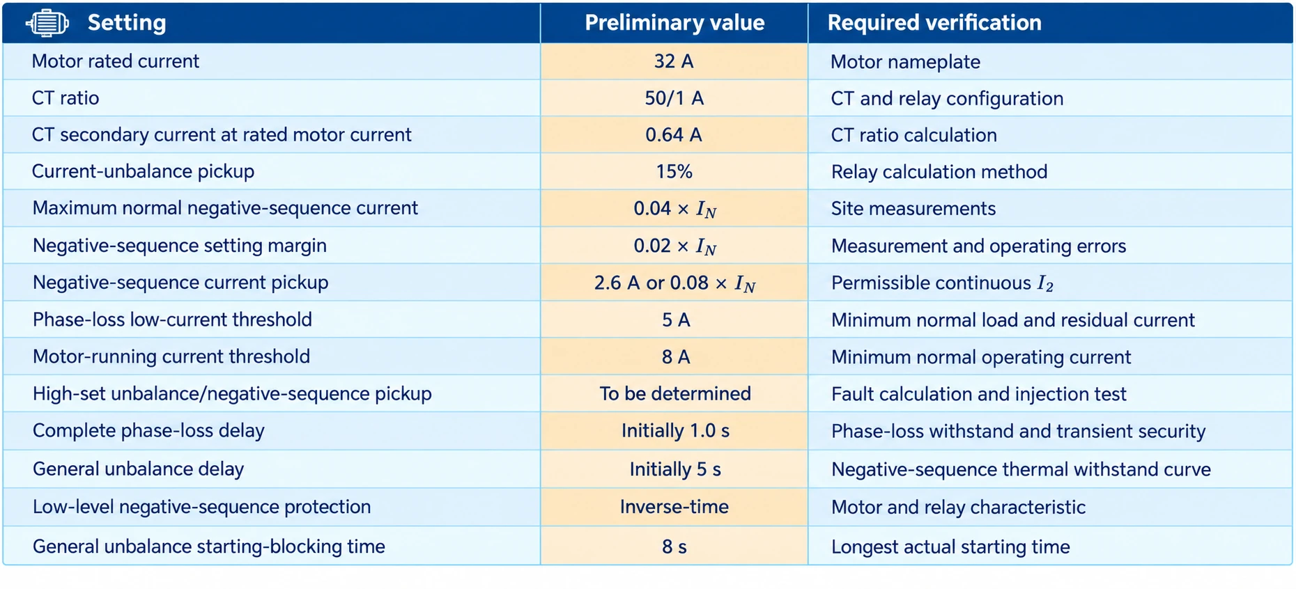 All values are preliminary. Final settings must be based on the motor manufacturer’s thermal data, actual operating measurements, relay characteristics and commissioning-test results.
9. Motor Phase-Loss Protection Testing
Phase-loss protection should preferably be verified using a relay test set or other suitable secondary current-injection equipment. Routine testing by operating the motor under a real phase-loss condition is not recommended.
9.1 Secondary Injection Testing
A relay test set should be used to inject simulated three-phase currents into the protection relay.
The following tests should be performed:
- Balanced three-phase current test;
- Progressive reduction of one phase current;
- Complete phase-loss simulation;
- Current-unbalance pickup test;
- Negative-sequence current pickup test;
- High-set negative-sequence or current-unbalance test;
- Negative-sequence inverse-time test;
- Starting-blocking logic test;
- Alarm and trip-output test.
Complete Phase-Loss Simulation
For a relay using magnitude-based phase-loss logic, a typical simplified test condition is:
\[ I_a<I_{\mathrm{low,set}} \]
and:
\[ I_b,\ I_c>I_{\mathrm{run,set}} \]
For example, one phase may be reduced to 0 A or to a small residual current below \(I_{\mathrm{low,set}}\), while the other two phase currents remain above \(I_{\mathrm{run,set}}\).
The test should verify that:
- The complete phase-loss element starts;
- The relay does not incorrectly interpret the condition as a stopped motor;
- The trip output operates within \(t_{\mathrm{phase\ loss}}\);
- The measured current unbalance and negative-sequence current agree with the relay algorithm;
- Alarm, trip and event records are generated correctly.
If negative-sequence quantities are being tested, the injected current phasors must represent the required fault condition. Setting one phase-current magnitude to zero while leaving the other two at arbitrary 120° phase displacement may not reproduce the actual sequence components of a phase-loss circuit.
For an ideal open phase in a star-connected motor with an isolated neutral and no neutral return path, where phase loss occurs in the supply or feeder circuit, the two remaining line-current phasors satisfy approximately:
\[ \vec I_b=-\vec I_c \]
and:
\[ \vec I_a=0 \]
This relationship is not universally applicable. For delta-connected motors, motors with a connected neutral, circuits with alternative return paths or faults occurring within the motor windings, the phase-current relationship may be different and must be determined from the actual circuit topology and fault location.
The exact injected current magnitudes and phase angles should therefore be obtained from:
- The approved protection test plan;
- The relay application manual;
- The motor connection arrangement;
- The applicable fault study.
The following should be recorded:
- Injected phase-current magnitudes and angles;
- Actual pickup current;
- Calculated current unbalance;
- Positive- and negative-sequence currents;
- Protection pickup level;
- Alarm operating time;
- Trip operating time;
- Protection behaviour during starting blocking;
- Correct discrimination between complete phase loss and general current unbalance.
9.2 CT Circuit Safety
Never open a CT secondary circuit while current is flowing in the CT primary circuit.
An open-circuited CT secondary can develop a dangerous high voltage, creating a risk of electric shock, insulation failure or equipment damage.
If CT-circuit supervision or secondary-circuit abnormality functions must be tested:
- Confirm that no current is flowing in the CT primary circuit;
- Isolate the relevant equipment and implement the required safety precautions;
- Use test terminals with an appropriate CT shorting facility;
- Follow the relay and test-equipment manufacturers’ procedures;
- Ensure that the work is performed by suitably qualified personnel.
- Motor phase loss must not be simulated by casually removing one phase CT conductor.
9.3 Primary-Circuit Functional Checks
Primary-circuit checks should normally be performed with the motor isolated. They should verify:
- CT installation position;
- CT polarity and phase sequence;
- Contactor or circuit-breaker auxiliary-contact status;
- Trip-output circuit;
- Alarm and interlocking circuits;
- Correct opening of the contactor or circuit breaker following a protection operation.
Starting a motor after deliberately removing one phase fuse is not recommended. Even with the motor unloaded, actual phase-loss starting may cause stalling, overheating or mechanical stress.
If a project specification explicitly requires a primary phase-loss test, it should be performed only under a dedicated procedure approved by the motor manufacturer, protection-equipment manufacturer and responsible project engineer, with strict limits on the test voltage, current and duration.
10. Motor Phase-Loss Protection Setting Considerations
- Use the motor nameplate rated current wherever available; do not rely solely on a calculated value.
- Confirm the current-unbalance formula implemented by the protection relay.
- Different current-unbalance algorithms can produce substantially different results and must not share the same setting without verification.
- Ensure that the negative-sequence pickup satisfies:
\[ I_{2,\mathrm{normal,max}}+I_{\mathrm{margin}} < I_{2,\mathrm{set}} \leq I_{2,\mathrm{continuous,allow}} \]
and confirm the motor manufacturer’s permissible continuous negative-sequence current.
- Determine \( I_{\mathrm{margin}} \) from normal operating variation, CT error and relay error. Algebraic addition may be used as a conservative engineering estimate; more precise assessments should apply an appropriate error-combination method.
- Apply a minimum positive-sequence current threshold when using the \( I_2/I_1 \)ratio.
- For important motors, use an inverse-time characteristic co-ordinated with the rotor negative-sequence withstand capability.
- Base the phase-loss low-current threshold on the minimum normal operating current rather than applying a fixed percentage of rated current.
- The motor-running current threshold should normally be higher than the phase-loss low-current threshold and lower than the minimum normal operating current.
- Determine high-set current-unbalance and negative-sequence thresholds from the relay algorithm, fault calculations and complete phase-loss test results rather than applying universal fixed multipliers.
- If no separate high-set stage is available, a shorter complete phase-loss delay may be considered only after transient-security and thermal-withstand verification. A shorter delay improves speed but does not increase pickup sensitivity.
- Ensure that current-unbalance and negative-sequence elements can operate independently of the complete phase-loss low-current logic.
- Use separate operating characteristics for complete phase loss, severe current unbalance and lower sustained negative-sequence current.
- Treat a 5–10 s current-unbalance delay only as an initial reference and verify it against the motor’s negative-sequence thermal withstand curve.
- Base the starting-blocking time on the longest actual starting time under the most onerous operating conditions.
- Confirm whether complete phase-loss protection remains active during starting.
- Verify the CT ratio, secondary rating, polarity, phase sequence, connection and whether relay settings are expressed as primary or secondary values.
- Use current magnitudes and phase angles appropriate to the actual motor winding connection and fault location when testing negative-sequence and phase-loss protection.
- A zero-sequence CT is intended mainly for earth-fault protection and cannot replace the three phase CTs for phase-loss detection.
- Co-ordinate phase-loss protection with negative-sequence protection, the motor thermal model and overload protection.
- Use secondary current injection for routine protection testing. Never open a CT secondary circuit while current is flowing in its primary circuit.
Conclusion
The fundamental purpose of motor phase-loss protection is to detect a substantial reduction in one phase current, severe three-phase current unbalance and increased negative-sequence current.
Voltage-based protection is suitable for detecting phase loss occurring upstream of the voltage measurement point. If phase loss occurs downstream, such as in a contactor, motor cable or internal motor winding, voltage-based protection may not detect it. Induced or regenerated voltage during motor operation may also reduce its sensitivity.
Complete phase-loss protection and independent current-unbalance/negative-sequence protection perform different but complementary functions:
- Complete phase-loss protection provides rapid tripping for a complete or near-complete phase interruption.
- Independent current-unbalance and negative-sequence elements protect against partial phase loss, resistive phase connections and sustained asymmetrical operation.
Neither protection level can replace the other.
The negative-sequence current pickup must be higher than the maximum negative-sequence current occurring during normal service, including an appropriate measurement margin, while remaining no higher than the motor’s permissible continuous negative-sequence current:
\[ I_{2,\mathrm{normal,max}}+I_{\mathrm{margin}} < I_{2,\mathrm{set}} \leq I_{2,\mathrm{continuous,allow}} \]
High-set current-unbalance and negative-sequence thresholds should be derived from the relay algorithm, fault calculations, motor operating conditions and complete phase-loss test results. Universal fixed multipliers should not be applied without verification.
Protection settings should be based on the motor nameplate current, minimum normal operating current, maximum normal negative-sequence current, longest actual starting time, CT ratio and motor thermal withstand capability. Complete phase loss should normally operate with a short delay, while severe current unbalance should use a separately verified definite-time stage and lower sustained negative-sequence current should be handled by an inverse-time element.
Final settings must be determined using motor-manufacturer data, the protection relay’s actual algorithms, site operating measurements, fault studies and secondary-injection test results.


