GWPR200‑M Motor Protection Relay
Product Desc
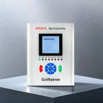
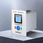
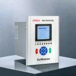
The GWPR200‑M is a motor protection relay developed by GoWatron. It provides integrated protection, measurement, control and communication for asynchronous motors operating in unearthed, resistance‑earthed and solidly‑earthed power systems rated up to 35 kV. The relay supports both centralized panel mounting and decentralized installation directly in switchgear.
- Equipped with 2 Ethernet ports supporting IEC 60870‑5‑103 over Ethernet;
- 1 RS‑485 interface supporting Modbus RTU;
- Supports multiple time‑synchronization methods, including SNTP, IRIG‑B and message‑based time synchronization.
- The relay can be easily integrated into a power monitoring or SCADA system, providing remote measurement, remote signalling, remote control and transmission of protection events.




Accuracy
≤ 0.2%

Quick Response
≤ 100ms

Reliable Protection
Comprehensive Protection

Quality Assurance
ISO 9001 Certified

Technical Support
24/7 Expert Support

Fast Delivery
Global Shipping

Warranty
2-Year Warranty
Product Introduction
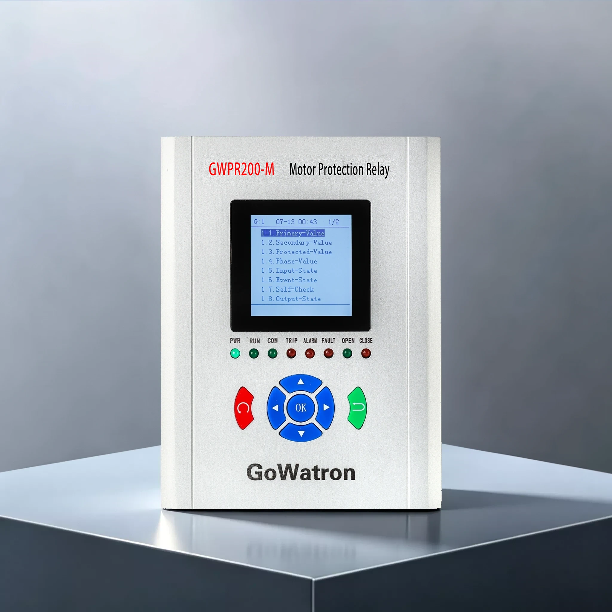
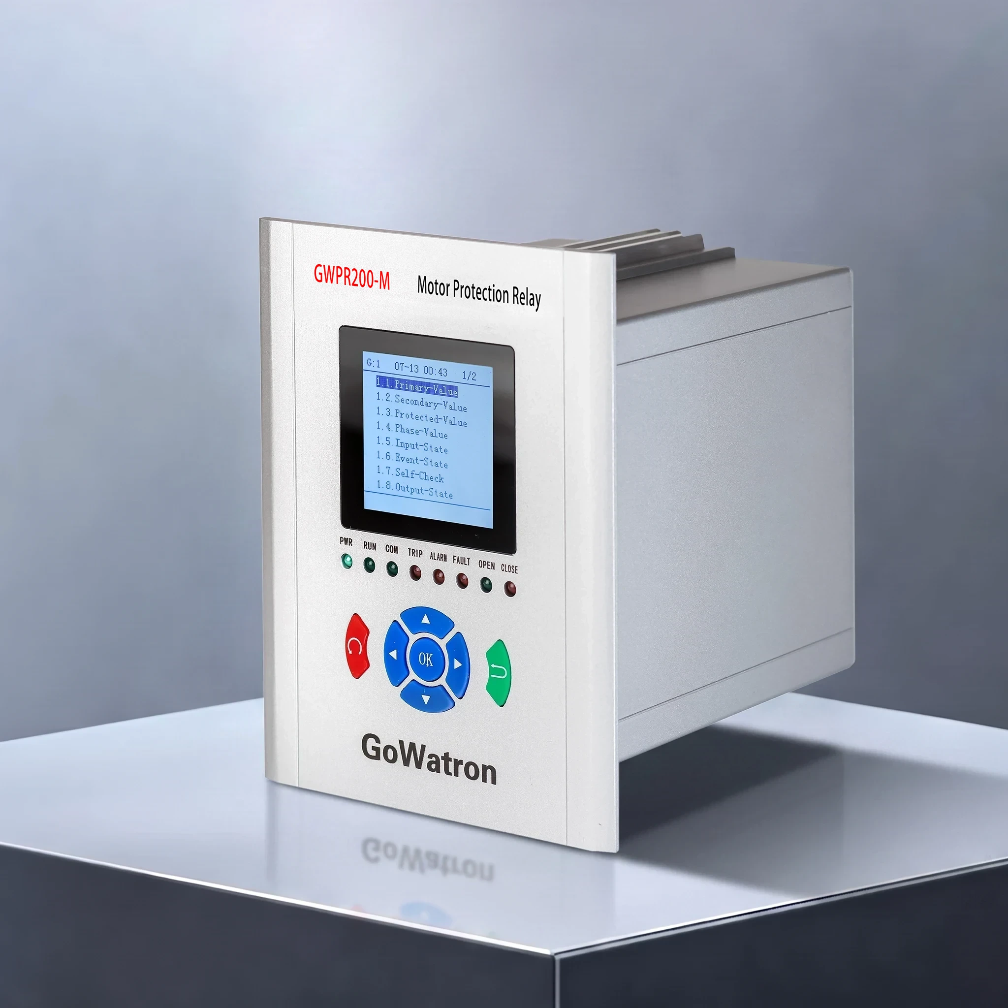
- The GWPR200‑M motor protection relay is built on a 32‑bit high‑speed MCU and DSP‑based sampling architecture. Its large LCD with a Chinese‑language interface clearly displays current, voltage, power, frequency, operating status and complete protection event information.
- The relay incorporates a complete circuit‑breaker control circuit. Each output relay channel can be independently configured for protection tripping, remote opening and closing, fault alarms and other signal outputs.
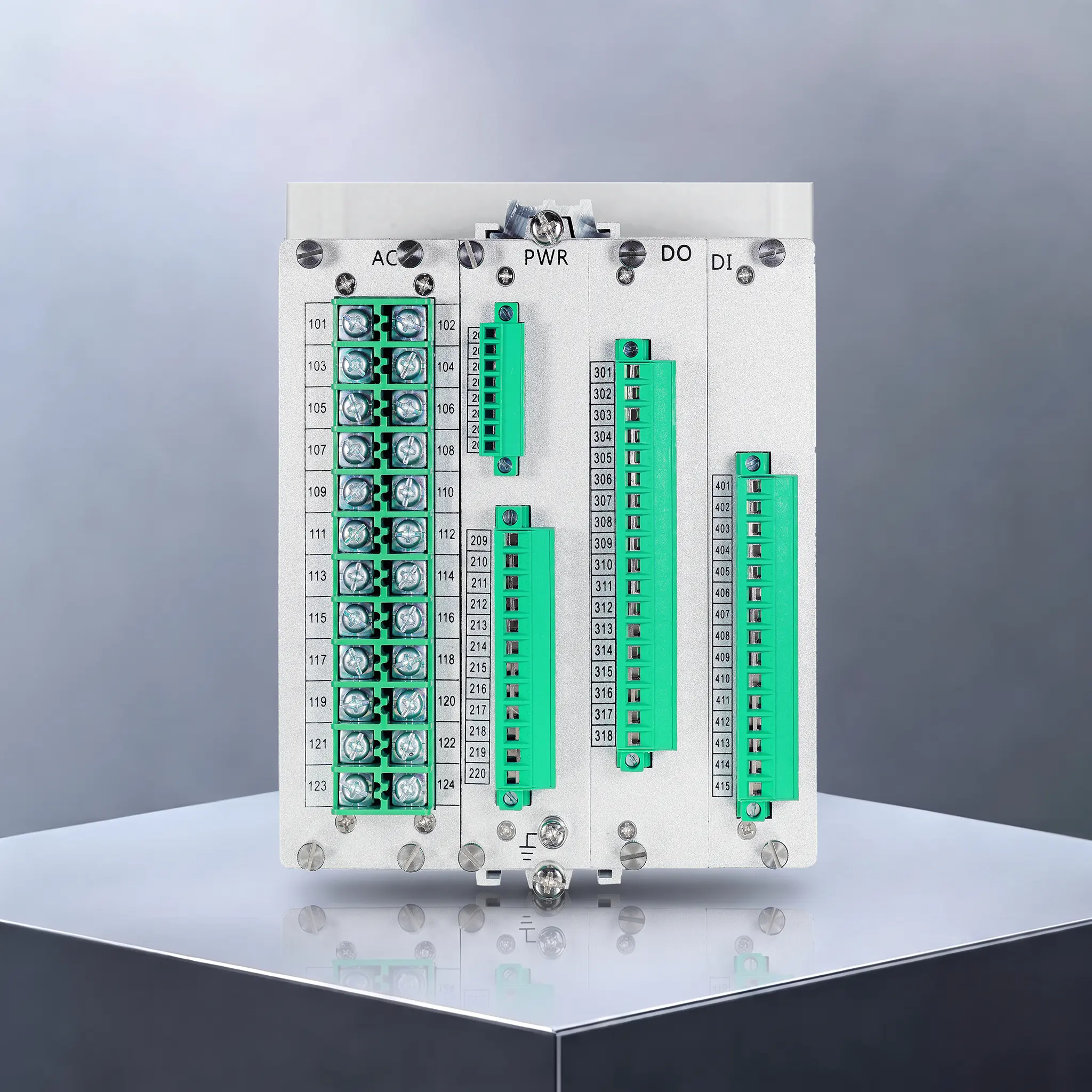
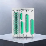
- It features comprehensive self‑diagnostic functions and multiple event‑recording capabilities. Its modular hardware design comprises an AC analog‑input board, PWR power‑supply board, DO output board and DI digital‑input board. The relay delivers stable and reliable operation in industrial environments subject to severe electromagnetic interference.
Product Functions
Protection Functions
- (ANSI 50P/51P) Three‑phase Time‑graded Overcurrent Protection (Trip)
- (ANSI 51P) Phase Overcurrent Inverse‑time Protection (Trip; Standard Inverse, Very Inverse or Extremely Inverse selectable)
- (ANSI 49M) Motor Thermal Overload Protection (Alarm / Trip selectable)
- (ANSI 51LR) Locked‑rotor Protection (Trip)
- (ANSI 46M‑1) Negative‑sequence Overcurrent Stage I Protection (Trip)
- (ANSI 46M‑2) Negative‑sequence Overcurrent Stage II Protection (Alarm / Trip selectable)
- (ANSI 46M) Negative‑sequence Overcurrent Inverse‑time Protection (Trip; Standard Inverse, Very Inverse or Extremely Inverse selectable)
- (ANSI 51N) Residual Overcurrent Protection (Alarm / Trip selectable)
- (ANSI 48) Prolonged Start‑up Protection (Trip)
- (ANSI 66) Start‑interval Control and Restart Inhibit (Motor start inhibited)
- (ANSI 27) Undervoltage Start Inhibit (Motor start inhibited)
- (ANSI 47) Voltage Phase‑loss and Phase‑unbalance Protection (Trip)
- Fuse‑Contactor (F‑C) Circuit Overcurrent Trip Blocking
- (ANSI 59) Overvoltage Protection (Trip)
- (ANSI 27) Undervoltage Protection (Alarm / Trip selectable)
- (ANSI 59N) Residual Overvoltage Protection (Alarm / Trip selectable)
- (ANSI 81U) Underfrequency Protection (Trip)
- (ANSI 60 / VTS) VT/PT Circuit Supervision (Alarm)
- Control‑circuit Supervision (Alarm)
- System Power‑loss Supervision (Alarm / Trip selectable)
- (ANSI 26) Temperature Rise (Alarm)
- (ANSI 26) Overtemperature (Trip)
Note: F‑C circuit overcurrent trip blocking, control‑circuit supervision and system power‑loss supervision are programmable logic functions without dedicated ANSI/IEEE C37.2 device function numbers. ANSI 60 may be used for VT/PT circuit supervision based on voltage‑unbalance criteria.
Measurement & Control Functions
- Measures three‑phase phase‑to‑neutral voltages, phase‑to‑phase voltages and residual voltage; three‑phase protection currents, metering currents and residual current; active power, reactive power, power factor and frequency; and four‑quadrant electrical energy.
- Provides 14 digital inputs and 8 programmable volt‑free relay outputs for remote control and signalling. It also supports Sequence of Events (SOE) recording and fault waveform recording, including pre‑fault and post‑fault waveform data.
Human‑Machine Interface & Commissioning Functions
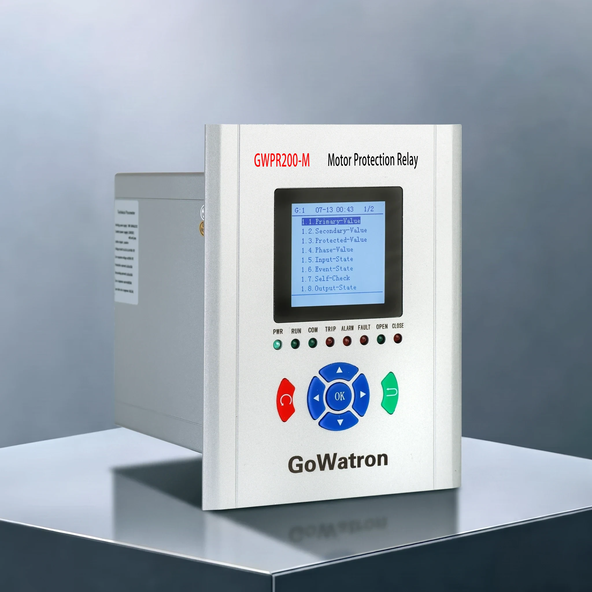
- Large LCD with a Chinese‑language interface and status indicators for Power, Run, Communication, Trip, Alarm, Fault, CB Open and CB Closed. The keypad allows users to modify protection settings, view event records and browse fault waveform records. Multiple setting groups can be selected and copied.
- Local commissioning functions include relay output testing, communication testing, event simulation and system reset, facilitating on‑site testing and commissioning.
Key Technical Specifications
- Operating Environment: Operating temperature: −40°C to +70°C; storage temperature: −40°C to +80°C
- Rated Electrical Parameters: CT secondary rated current: 1 A or 5 A selectable; PT secondary rated voltage: 100 V; auxiliary power supply: 100–264 V AC/DC
- Accuracy Class: Voltage and current: Class 0.5; frequency accuracy: ±0.01 Hz
- EMC Compliance: Complies with the immunity requirements of GB/T 14598.26‑2015, including electrostatic discharge, surge, electrical fast transient/burst and radio‑frequency electromagnetic‑field immunity
- Recording Capacity: 128 protection event records, 128 alarm records, 128 remote‑signalling event records, 128 operation records, 16 self‑diagnostic event records and 32 fault waveform records
- Hardware Interfaces: 14 digital inputs and 8 programmable volt‑free relay outputs; contact rating: 8 A at 250 V AC
Application Scenarios
- Protection, measurement and control of asynchronous motor circuits in industrial and mining auxiliary power systems rated up to 35 kV
- Local installation in high‑voltage motor switchgear used in chemical plants, metallurgical facilities, water treatment plants, mines and building power distribution systems
- Centralized panel mounting for station‑service motor protection applications in substations
- Motor protection in fuse‑contactor (F‑C), resistance‑earthed and unearthed distribution systems
- Motor circuits requiring integration with power automation or SCADA systems for remote measurement, remote signalling and remote control
- High‑power motors requiring comprehensive motor‑specific protection, including thermal overload, locked‑rotor protection, prolonged start‑up protection and restart inhibit


