


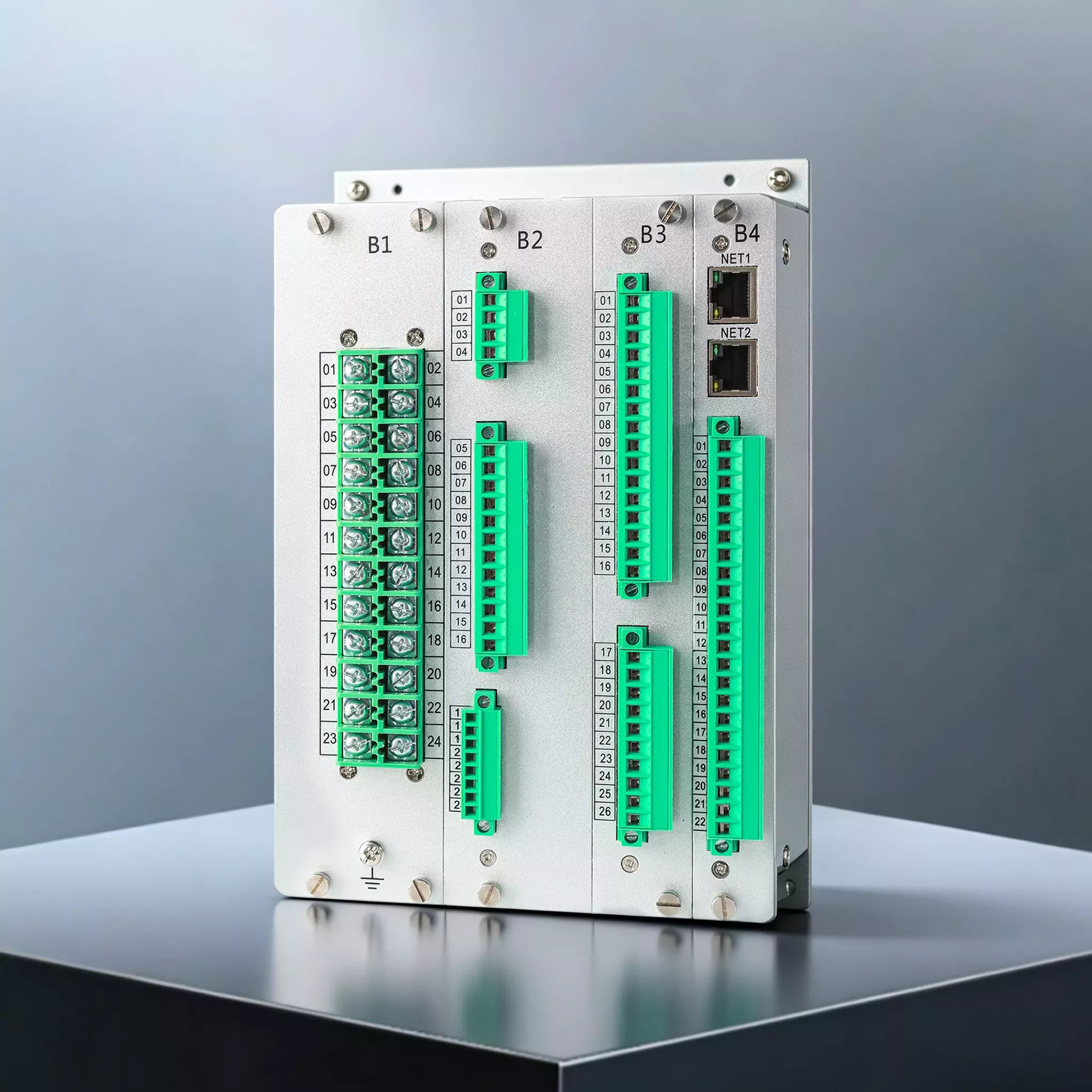




GWPR300‑ABT‑B Automatic Bus Transfer and Bus-Tie Protection Relay
Product Desc
The GoWatron GWPR300‑ABT‑B Automatic Bus Transfer and Bus-Tie Protection Relay is designed for automatic source transfer applications in 132 kV, 66 kV, 33 kV and 11 kV power systems. It provides automatic transfer control for incoming circuit breakers and bus-section/bus-tie circuit breakers, together with integrated protection, measurement, monitoring and local/remote control functions.
- The relay is equipped with dual Ethernet ports supporting IEC 60870‑5‑103 over Ethernet and IEC 60870‑5‑104. IEC 61850 communication is available as an optional feature.
- An RS‑485 serial interface supporting Modbus RTU is also provided.
- Supported time-synchronization methods include IRIG‑B, SNTP and protocol-based




Accuracy
≤ 0.2%

Quick Response
≤ 100ms

Reliable Protection
Comprehensive Protection

Quality Assurance
ISO 9001 Certified

Technical Support
24/7 Expert Support

Fast Delivery
Global Shipping

Warranty
2-Year Warranty
Product Introduction
- The GWPR300‑ABT‑B Automatic Bus Transfer and Bus-Tie Protection Relay is built around a high-performance 32-bit microcontroller incorporating a digital signal processor (DSP) and floating-point unit (FPU). It independently performs protection and automatic transfer logic calculations, trip and close output control, event recording, fault oscillography and communication processing.
- The relay incorporates a dedicated 16-bit A/D conversion system together with invalid-sample detection and filtering algorithms, providing reliable AC analogue signal acquisition in demanding electromagnetic environments.
- The relay uses a fully enclosed chassis with physical isolation between power circuits and signal circuits. Its coordinated grounding, shielding, filtering, circuit isolation, and hardware and software EMC measures improve immunity to electromagnetic interference and support compliance with applicable international EMC standards.
- The relay features a user-friendly human-machine interface and modular, independently configurable protection and control elements. Its modular hardware design facilitates configuration, routine maintenance and functional expansion.
- Local keypad operation, protection setting configuration and commissioning tests are supported. Remote monitoring, operation and control can be performed through a station SCADA or substation automation system.
- Flexible installation options allow the relay to meet the requirements of both centralized panel-mounted and distributed switchgear-mounted applications
Main Functions
Automatic Bus Transfer Function
- The automatic bus transfer logic is supervised by undervoltage (ANSI 27) and overvoltage (ANSI 59) elements, source-availability checks, circuit-breaker status, transfer permissive conditions and transfer-blocking conditions.
- Available transfer schemes include:
- Automatic Transfer Mode 1 with Automatic Retransfer
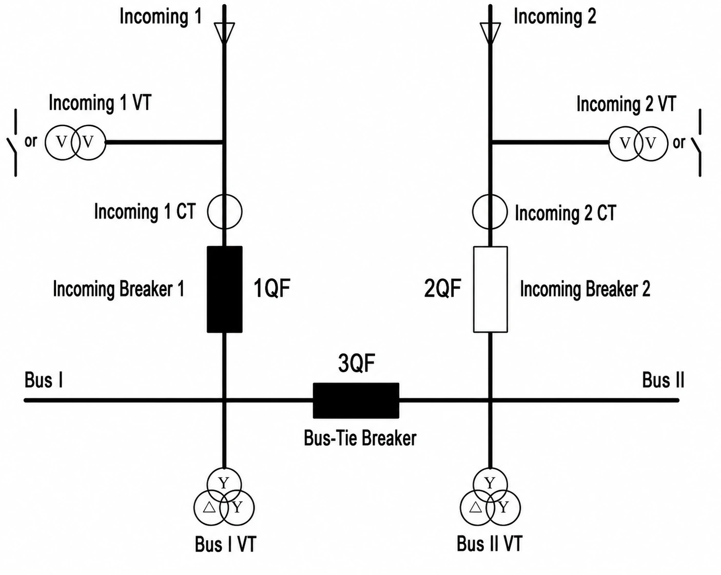
Typical Application of ABT Mode 1
- Automatic Transfer Mode 2 with Automatic Retransfer
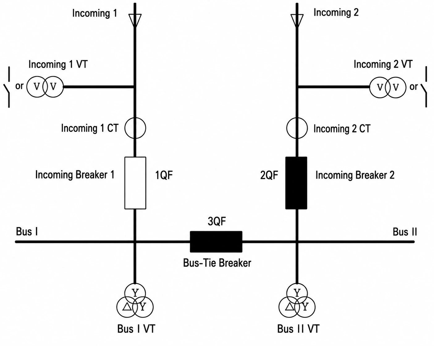
Typical Application of ABT Mode 2
- Automatic Transfer Mode 3 with Automatic Retransfer
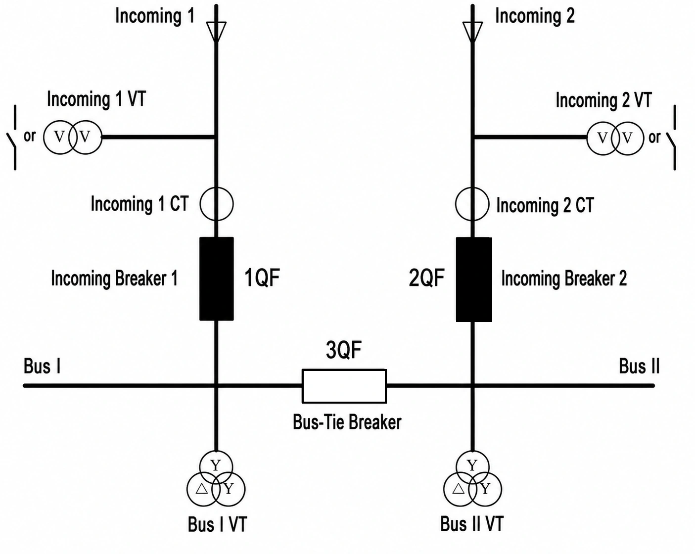
Typical Application of ABT Mode 3
- Automatic Transfer Mode 4 with Automatic Retransfer
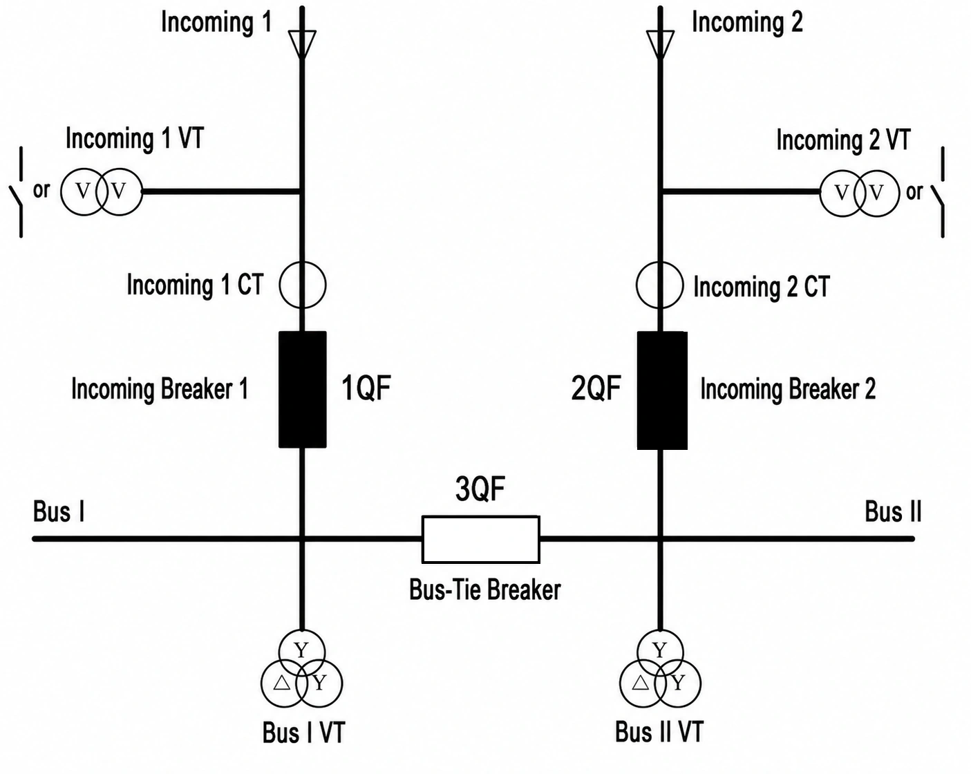
Typical Application of ABT Mode 4
- Automatic retransfer restores the power system to its normal operating configuration after the preferred source has returned and all configured retransfer conditions have been satisfied.
- Note: Due to webpage space and layout limitations, the arming conditions, disarming conditions, initiation conditions, operating conditions, automatic retransfer conditions and detailed operating logic for the four ABT modes are not presented in full. Please contact our staff to obtain the relevant schematic and logic diagrams.
Protection Functions
- (ANSI 50/51) Three-Stage Overcurrent Protection, Stages I/II/III (Trip)
- (ANSI 51) Inverse-Time Overcurrent Protection (Standard Inverse, Very Inverse or Extremely Inverse characteristic selectable)
- (ANSI 49) Thermal Overload Protection (Alarm / Trip selectable)
- (ANSI 50) Bus Energization Overcurrent Protection (Trip)
- Trip Circuit Supervision (TCS) and Close Circuit Supervision (CCS) (Alarm)
Other Auxiliary Functions
Measurement and Status Acquisition
- The relay measures multiple sets of busbar voltages, source-side voltages, three-phase protection currents, incoming-line currents and system frequency. It also provides 21 binary inputs, 13 independently configurable relay output contacts and one dedicated power-failure alarm contact.
Event and Fault Recording
- The relay automatically stores protection events, alarm events, binary input status changes, operation logs, self-supervision events and fault oscillography records. Local report printing is supported when connected to a compatible printing system.
Local Commissioning and Maintenance
- Functions include relay output tests, trip and close circuit tests, communication tests, event simulation, device reset, protection setting management, and setting group selection and switching.
Application Scope
- The GWPR300‑ABT‑B is suitable for automatic source transfer and bus-tie protection applications in 132 kV, 66 kV, 33 kV and 11 kV substations and power systems.
Typical applications include automatic transfer control for:
- Incoming circuit breakers
- Bus-section and bus-tie circuit breakers
- Circuit breakers in internal-bridge connections
- Circuit breakers on the high-voltage and low-voltage sides of main transformers
- Dual-incomer, sectionalized single-bus systems
- Main–tie–main (MTM) configurations
- The relay can be centrally installed in a protection and control panel. In applicable 11 kV and 33 kV installations, it may also be mounted locally inside medium-voltage switchgear.


