Line Current Differential Protection (ANSI 87L): Operating Principle and Restraint Characteristic
Line current differential protection (ANSI 87L) is a communications-assisted unit protection scheme that compares the currents measured at all terminals of the protected line. It is normally applied as the main protection for the line.
The protection operates according to Kirchhoff’s current law. Current transformers (CTs) are installed at both ends, or at all terminals, of the protected line. Current sample data are exchanged through dedicated optical-fibre links or digital communication channels that meet the required protection performance criteria. The current data from all terminals are synchronized, time-aligned and normalized before the differential and restraint quantities are calculated.
A common reference direction is applied at all terminals: current flowing from each busbar into the protected zone is defined as positive. The protection zone is normally defined by the locations of the CTs at the line terminals.
1. Normal Operation or External Fault
During normal operation, or when a fault occurs outside the line differential protection zone, the currents entering and leaving the protected zone are substantially balanced.
For a two-terminal line, the differential current can be expressed as:
\[ I_{\mathrm{diff}} = \left| \dot{I}_1+\dot{I}_2 \right| \approx 0 \]
where:
- \( \dot{I}_1 \) is the current phasor at Terminal 1 after CT ratio and polarity compensation and time alignment;
- \( \dot{I}_2 \) is the current phasor at Terminal 2 after CT ratio and polarity compensation and time alignment;
- \( I_{\mathrm{diff}} \) is the differential current.
For a multi-terminal line, including a teed line, with \(n\) terminals, the differential current can generally be expressed as:
\[ I_{\mathrm{diff}} = \left| \sum_{k=1}^{n}\dot{I}_k \right| \]
where:
- \( n \)is the number of line terminals;
- \( \dot{I}_k \) is the compensated and time-aligned current phasor at Terminal \( k \).
Ideally, the differential current should be close to zero during normal operation or an external fault. In practice, a certain amount of unbalance current may be present due to:
- CT ratio and phase-angle errors at the different line terminals;
- Differences in CT type, secondary burden, remanence and transient performance;
- Transient or steady-state CT saturation during an external short circuit;
- Line charging current resulting from distributed line capacitance;
- Residual sampling-synchronization or time-alignment errors between terminals;
- Asymmetric communication-channel delay or delay variation;
- Measurement errors in the CT secondary circuits and protection relays.
The line differential protection remains stable when the differential current does not satisfy the operating criteria.
For long overhead lines, extra-high-voltage lines or cable circuits, line charging current may represent a significant differential-current component. Some numerical line differential relays can compensate for charging current using measured voltages and configured line parameters. The availability, application limits and settings of this function must be determined from the technical documentation for the specific relay.
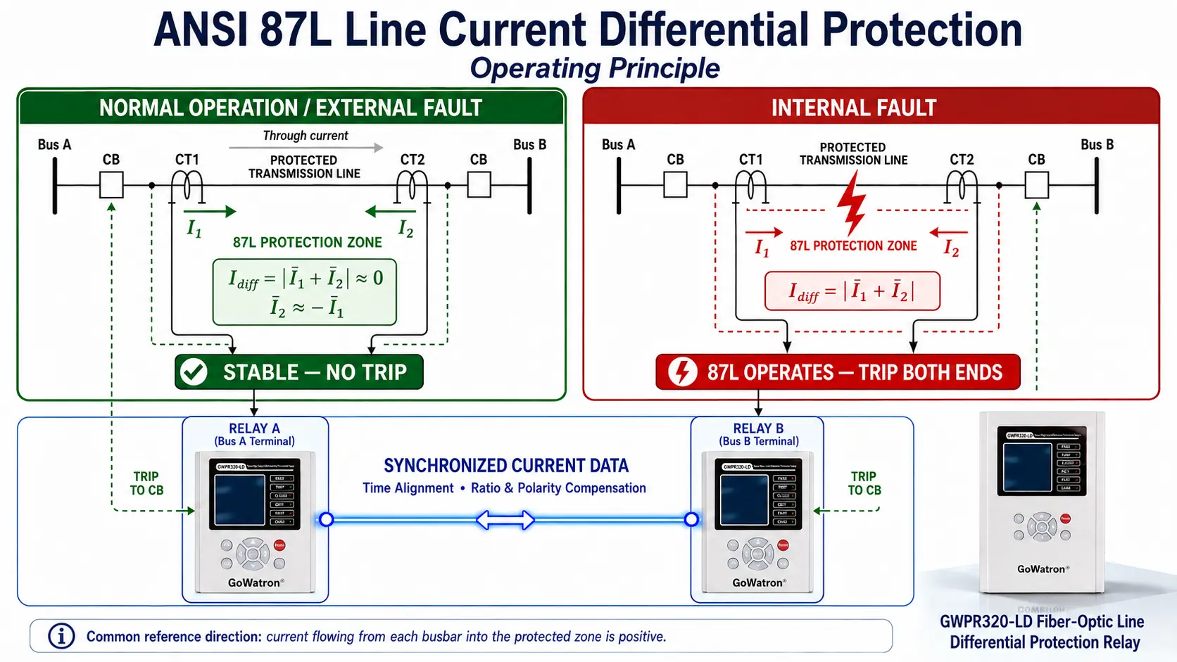
2. Internal Line Fault
When a fault occurs within the protection zone defined by the terminal CTs, the short-circuit currents contributed from the line terminals flow towards the internal fault point.
After the terminal currents have been referred to the common positive direction—flowing from each busbar into the protected zone—the fault-current contributions add in the differential calculation, producing a significant differential current.
For a two-terminal line:
\[ I_{\mathrm{diff}} = \left| \dot{I}_1+\dot{I}_2 \right| \]
For a multi-terminal line:
\[ I_{\mathrm{diff}} = \left| \sum_{k=1}^{n}\dot{I}_k \right| \]
When the differential current satisfies the operating characteristic, and the communication channel and associated protection logic permit operation, the line differential protection issues a high-speed trip command. The circuit breakers at all line terminals are opened to isolate the faulted line from the power system.
Line differential protection is normally applied without an intentional time delay for protection coordination. However, the total fault-clearing time still includes:
- Relay data-processing and decision-making time;
- Communication data-transmission time;
- Trip-output circuit operating time;
- Circuit-breaker opening and arc-extinction time.
The technically appropriate descriptions are therefore “high-speed operation” or “operation without an intentional coordination delay,” rather than “instantaneous operation” in an absolute sense.
If an abnormal condition is detected in the communication channel, CT secondary circuit or sampled-current data, the relay may initiate an alarm, block the affected differential element or phase, disable the line differential protection, or rely on the applicable backup protection. The specific response depends on the relay design and project configuration.
3. Percentage-Restraint Characteristic
Numerical line differential protection normally employs a percentage-restraint, also known as a biased-differential, characteristic to maintain stability during normal load conditions, external faults, CT measurement errors and CT saturation.
The basic principles are:
- At low restraint current, the protection maintains high operating sensitivity;
- As the restraint current increases, the differential operating threshold increases accordingly;
- For an internal fault, the differential current increases significantly and the protection can operate at high speed;
- During a high-current external fault, the protection should remain stable even if CT errors or CT saturation produce a certain amount of unbalance current.
3.1 Differential Current
For a two-terminal line, the differential current is commonly defined as:
\[ I_{\mathrm{diff}} = \left| \dot{I}_1+\dot{I}_2 \right| \]
3.2 Restraint Current
One commonly used definition of restraint current is:
\[ I_{\mathrm{rest}} = \frac{ \left|\dot{I}_1\right| + \left|\dot{I}_2\right| }{2} \]
Some relays use the greater of the two terminal-current magnitudes as the restraint current:
\[ I_{\mathrm{rest}} = \max \left( \left|\dot{I}_1\right|, \left|\dot{I}_2\right| \right) \]
where:
- \( I_{\mathrm{rest}} \) is the restraint current;
- \( \left|\dot{I}_1\right| \) is the magnitude of the current phasor at Terminal 1;
- \( \left|\dot{I}_2\right| \) is the magnitude of the current phasor at Terminal 2.
The definitions of differential current and restraint current vary between relay designs. Protection settings must therefore be calculated using the equations and operating characteristics specified for the particular relay. Definitions from different relay manufacturers or relay models must not be mixed.
3.3 Typical Single-Slope Restraint Characteristic
The following is an example of a continuous single-slope percentage-restraint characteristic. It is provided only to explain the fundamental operating principle and does not represent the operating characteristic of every line differential relay.
The piecewise operating criterion can be expressed as:
\[ I_{\mathrm{diff}} \geq \begin{cases} I_{\mathrm{op.min}}, & I_{\mathrm{rest}} \leq I_{\mathrm{rest.min}} \\[6pt] I_{\mathrm{op.min}} + K_{\mathrm{rest}} \left( I_{\mathrm{rest}} – I_{\mathrm{rest.min}} \right), & I_{\mathrm{rest}} > I_{\mathrm{rest.min}} \end{cases} \]
where:
- \( I_{\mathrm{diff}} \) is the differential current;
- \( I_{\mathrm{rest}} \) is the restraint current;
- \( I_{\mathrm{op.min}} \)is the minimum differential operating current;
- \( I_{\mathrm{rest.min}} \) is the restraint-current breakpoint;
- \( K_{\mathrm{rest}} \) is the restraint coefficient or restraint slope.
This operating characteristic means that:
- When \( I_{\mathrm{rest}}\leq I_{\mathrm{rest.min}} \), the operating threshold is determined by the minimum differential operating current \(I_{\mathrm{op.min}}\);
- When \( I_{\mathrm{rest}}>I_{\mathrm{rest.min}} \), the differential operating threshold increases with the restraint current;
- A higher\( K_{\mathrm{rest}} \)improves stability during high-current external faults but may reduce sensitivity to internal faults under high-restraint-current conditions.
A particular relay may define the operating boundary using either a strict “greater than” condition or a “greater than or equal to” condition. The relay manufacturer’s technical documentation must therefore be followed.
3.4 Other Differential Protection Algorithms
Modern numerical line differential protection may also incorporate:
- Dual-slope or multi-section percentage-restraint characteristics;
- CT saturation detection and security logic;
- Incremental-quantity differential elements;
- Line charging-current compensation;
- Zero-sequence or negative-sequence differential elements;
- Adaptive restraint;
- Sampled-data validity supervision;
- Communication-channel delay compensation;
- Channel-failure detection and protection fallback logic.
The purpose and logical priority of incremental-quantity, zero-sequence and negative-sequence differential elements vary between relay designs. They may be used to improve operating speed or sensitivity to particular types of fault. Their specific application must be determined from the relay algorithm and technical documentation.
The equations above are therefore intended to explain the fundamental principle of line differential protection. Actual setting calculations must be based on the differential-current definition, restraint-current definition, minimum operating current, restraint-current breakpoint, restraint slope and operating characteristic implemented in the particular relay.
4. Summary of the Operating Principle
Line current differential protection exchanges current sample data between all line terminals through a communication channel. The terminal data are synchronized, time-aligned and normalized before the differential and restraint currents are calculated using a common current-reference direction:
- During normal operation, the terminal currents are substantially balanced, the differential current remains low and the protection remains stable;
- During an external fault, the currents entering and leaving the protection zone remain substantially balanced, while percentage restraint and CT saturation detection improve protection stability;
- During an internal fault, the fault-current contributions from all terminals flow towards the fault point, causing the differential current to increase significantly. Once the operating criteria are satisfied, the protection trips the circuit breakers at all line terminals at high speed;
- For long overhead lines or cable circuits, line charging-current compensation may be applied where supported by the relay;
- If an abnormal condition occurs in the communication channel, sampled-current data or CT secondary circuit, the relay initiates the configured alarm, blocking or backup-protection response.
The protection zone is clearly defined by the CTs at the line terminals. Line current differential protection provides high-speed operation for internal faults and achieves selective fault clearance without relying on time grading with upstream or downstream protection. It also offers strong adaptability to changes in power-system operating conditions.
Line current differential protection is widely applied as the main protection for high- and medium-voltage overhead lines, cable circuits, critical interconnecting lines, teed lines and other multi-terminal circuits.


