Line Current Differential Protection (ANSI 87L): Functions, Protection Zone and Applications
The ANSI/IEEE device function number for line current differential protection is 87L. Its operating principle is based on comparing the currents measured at all line terminals and determining whether a fault is internal by calculating the difference between the currents entering and leaving the protected zone.
Hereinafter, it is referred to as “line current differential protection” or “differential protection.”
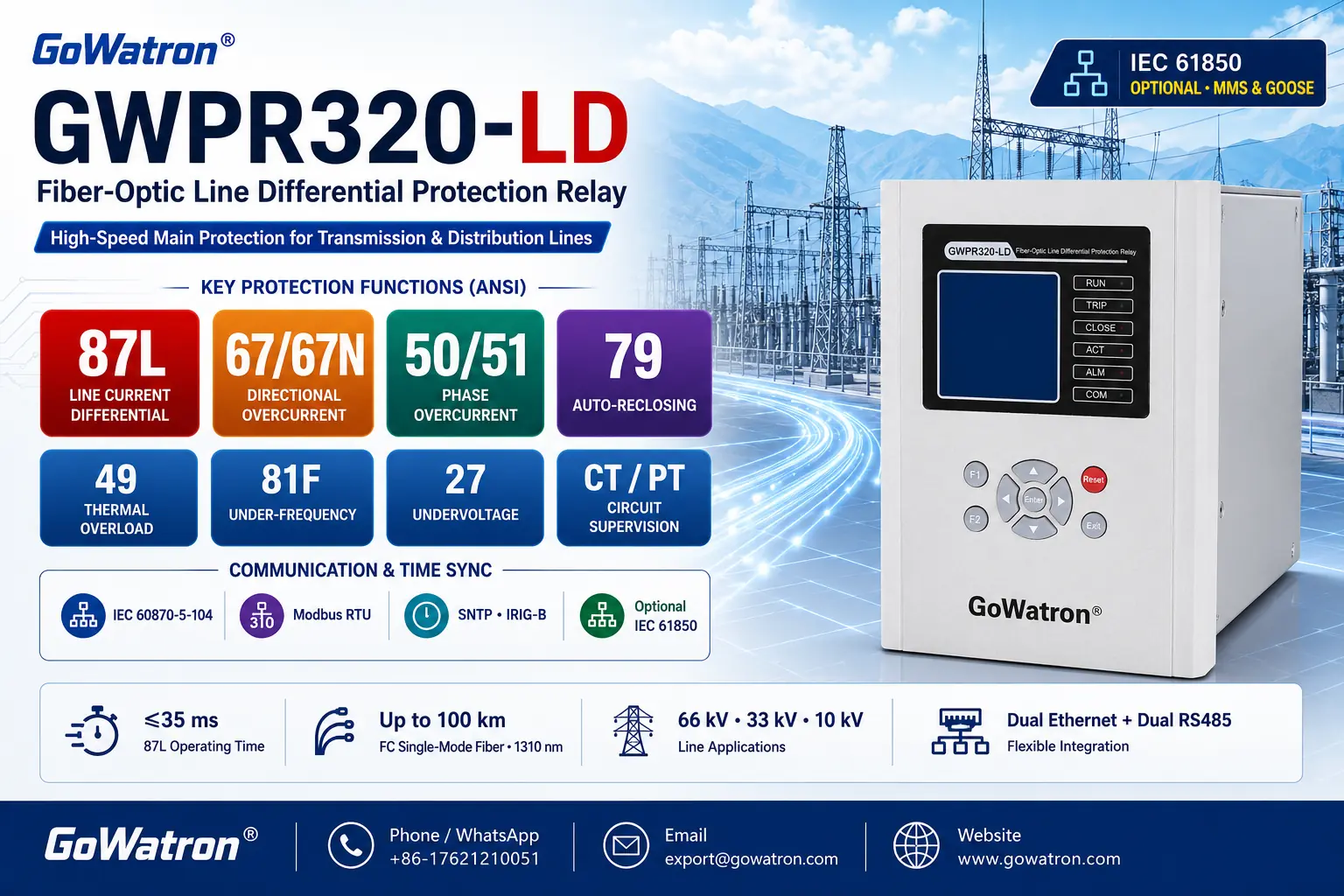
1. Application as the Main Line Protection
Line current differential protection is normally applied as the main protection for a transmission or distribution line. Its protection zone is defined by the locations of the current transformers (CTs) whose currents are included in the differential calculation.
Its principal functions include:
High-speed clearing of phase-to-phase faults, three-phase faults and earth faults within the protected zone;
Operation for internal faults without requiring time-grading coordination with protection on adjacent lines;
Adaptability to bidirectional power flow and changes in power-system operating conditions.
Line current differential protection is a unit protection scheme with a clearly defined protection zone. Its operating criterion is based on the differential calculation of currents measured at all terminals of the protected line. In principle, it does not provide remote backup protection for faults on adjacent lines.
Distance protection, directional overcurrent protection or other backup protection should therefore normally be provided. The specific configuration should be determined according to the voltage level, system configuration, neutral-earthing method and protection coordination requirements.
2. Protection Zone
The line current differential protection zone is the electrical area bounded by the CTs whose currents are included in the differential calculation. It is not defined simply by the positions of the circuit-breakers at the line terminals.
Provided that the CT locations, polarities, ratios, phase sequence and secondary connections are correct, and that the currents of all relevant branches are included in the differential calculation, line current differential protection can cover the entire line section bounded by the terminal CTs.
Whether a protection dead zone exists between a CT and a circuit-breaker depends on their relative positions and the primary system configuration:
- In gas-insulated switchgear (GIS), CTs are normally integrated within the bay. The electrical distance between the CT and circuit-breaker is therefore short, and the dead zone is usually small. Nevertheless, whether this section constitutes a protection dead zone must be determined from the CT arrangement, circuit-breaker position and protection-zone boundaries. It should not be assumed that GIS line differential protection is completely free of dead zones.
- In air-insulated switchgear (AIS), if a line CT is installed on the line side of the circuit-breaker, a fault between the circuit-breaker and the CT may lie outside the line differential protection zone. Such a fault must be cleared by busbar differential protection, dedicated dead-zone protection or another appropriate protection scheme.
- In breaker-and-a-half, double-breaker and multi-terminal arrangements, the currents from all CTs defining the boundaries of the line protection zone must be correctly included in the differential calculation.
Depending on the primary system configuration, the overall protection scheme may require:
- Dead-zone protection;
- Busbar differential protection;
- Circuit-breaker failure protection;
- Transfer-trip or intertripping logic.
It is therefore inappropriate to state categorically that line current differential protection provides “dead-zone-free protection for the entire line.” A more accurate statement is:
Line current differential protection provides high-speed protection for the entire electrical zone bounded by the terminal CTs. Its actual coverage and any terminal dead zones depend on the CT locations, circuit-breaker arrangement and primary system configuration.
3. Earth-Fault Differential Protection
Per-phase line current differential elements can normally detect both phase faults and earth faults within the protected zone.
For earth faults involving low fault current, weak-infeed conditions or high fault resistance, the following sensitive protection elements may be applied, depending on the system neutral-earthing method:
- Zero-sequence current differential protection;
- Earth-current differential protection;
- Negative-sequence current differential protection;
- Sensitive earth-fault protection.
These elements can improve sensitivity to certain high-resistance earth faults. Their actual detection capability, however, depends on:
- The system neutral-earthing method;
- Fault resistance;
- The magnitude and distribution of fault current among the line terminals;
- CT performance and the method used to derive or measure zero-sequence current;
- Differential pickup settings and restraint characteristics.
Different manufacturers may use designations such as 87LG, 87L0, 87LN or other identifiers for earth-current or zero-sequence differential functions. These suffixes are not fully standardized ANSI/IEEE device function numbers.
The recommended description in a technical document is:
Line zero-sequence current differential/earth-current differential protection—the exact function name and designation shall be in accordance with the protection relay documentation.
4. Principal Technical Advantages
The principal advantages of line current differential protection include:
- A clearly defined protection zone and high selectivity;
- High-speed operation for internal faults;
- No requirement for time coordination with protection on adjacent lines;
- High sensitivity to solid faults and faults with low fault resistance;
- Adaptability to bidirectional power flow and changing system operating conditions;
- Generally no direct susceptibility to load encroachment or power swings;
- Less dependence on line impedance parameters than distance protection;
- Applicability to both two-terminal and multi-terminal lines.
Line current differential protection may nevertheless be affected by CT saturation, sampling errors, communication-channel abnormalities and line charging current.
5. Principal Limitations
The principal limitations of line current differential protection include:
- Dependence on a reliable communication channel that meets protection requirements;
- The need for correct synchronization or time alignment of current data from all line terminals;
- The need to manage channel delay and asymmetrical channel delay correctly;
- Stringent requirements for correct CT polarity, ratio, phase sequence and secondary connections;
- The need to maintain security against CT saturation during high-current external faults;
- The need to account for charging current on long overhead lines and cable circuits;
- The requirement to include current from every relevant terminal on multi-terminal or tapped lines;
- Inability to provide remote backup protection for adjacent-line faults by itself.
The following three technical topics require particular attention during the design, settings calculation and commissioning of line current differential protection.
① Communications and Data Synchronization
Line current differential protection exchanges current samples or processed current data between line terminals through a communication channel. Channel availability, transmission delay, variations in channel delay and asymmetry between the transmit and receive paths can all affect the accuracy of the differential calculation.
Common data-synchronization methods used by modern line current differential protection include:
- Sample-time alignment based on round-trip channel-delay measurement;
- Absolute time synchronization based on an external time reference;
- Other manufacturer-specific data-synchronization or time-alignment algorithms.
Methods based on round-trip delay measurement normally assume that the transmit and receive delays are approximately equal. Significant asymmetry between the two directions can cause data misalignment and produce spurious differential current.
The protection relay should therefore normally provide:
- Communication-channel status supervision;
- Monitoring of channel delay and variations in channel delay;
- Alarms for excessive or sudden changes in channel delay;
- Detection of bit errors, lost frames and invalid data;
- Handling of data-synchronization errors;
- Blocking or fallback logic during channel abnormalities.
If the communication channel fails or its quality no longer satisfies the protection requirements, the differential function is normally blocked or taken out of service and a channel-failure alarm is issued. Integrated distance, overcurrent or other backup protection functions may remain in service.
Following restoration of the communication channel, the differential function may return to service automatically once channel quality, data synchronization and delay stability satisfy the specified criteria. Alternatively, manual confirmation may be required, depending on the project requirements.
The actual response to channel failure and restoration shall be determined by the protection relay design and configured scheme logic.
② Charging Current
The distributed capacitance of an overhead line or cable produces charging current. Because charging current enters the line from its terminals and flows through the distributed capacitance to earth, it can appear as differential current in the protection calculation.
This issue requires particular attention for:
- Long extra-high-voltage overhead lines;
- High-voltage and extra-high-voltage cable circuits;
- Submarine cable circuits;
- Lines whose charging current is close to the differential pickup setting.
Where charging current is significant, the following measures should be considered on the basis of engineering calculations and the available relay functions:
- Enable charging-current compensation;
- Coordinate the differential pickup setting and restraint characteristic appropriately;
- Verify the steady-state differential current under normal operating conditions;
- Verify protection stability during line energization, de-energization and fault transients.
Charging-current compensation can improve the sensitivity of differential protection on long lines and cable circuits. However, the compensation parameters must correspond to the actual line capacitance and applicable system operating conditions.
③ CT Performance
CTs used for line current differential protection should be selected and verified on the basis of the maximum short-circuit current, rated secondary current, secondary-circuit burden, decaying DC component, required protection operating time and relay algorithm.
Depending on the application, CT classes such as 5P, 10P, PX, TPX or TPY may be used. It is not appropriate to specify TPY or 5P20 universally for every line current differential protection application.
The CT application assessment should consider:
- Correct CT ratios, polarities and phase sequence at all terminals;
- Whether the actual CT secondary burden exceeds the rated burden;
- The likelihood and severity of CT saturation during high-current external faults;
- Whether the transient performance of the CTs is adequate for high-speed differential protection;
- Differential current caused by differences in CT performance between terminals;
- Whether the relay supports compensation for different CT ratios.
Different CT ratios may be used at the line terminals, provided that the rated currents, CT ratios and phase relationships are correctly configured in the protection relays and that the relays can perform the required current scaling.
For example, 5P20 indicates that a protection-class CT has a composite error not exceeding 5% at its rated accuracy-limit primary current—20 times its rated primary current—provided that the actual secondary burden does not exceed the rated burden.
In this designation, “P” denotes a protection-class CT, “5” indicates a composite-error limit of 5% under rated accuracy-limit conditions, and “20” is the rated accuracy limit factor.
This 5% composite-error limit applies under rated accuracy-limit conditions. It is not the same performance criterion as ratio error and phase displacement assessed around rated current under specified burden conditions.
Consequently, 5P20 must not be interpreted as meaning that “the permissible CT ratio error is ±5%” or that “the CT maintains 5% measurement accuracy under all current and burden conditions.”
The required CT class and parameters should ultimately be determined from the system short-circuit study, actual secondary-circuit burden and protection relay requirements.
6. Typical Applications
Line current differential protection is principally applied in the following three categories:
Voltage Levels and Line Types
- It is suitable for medium-voltage, high-voltage and extra-high-voltage overhead lines and cable circuits, including short and medium-length lines, as well as long lines for which the communication, synchronization and compensation requirements are satisfied.
Complex System Operating Conditions
- It is suitable for two-terminal infeed, bidirectional power flow, weak-infeed, multi-terminal and tapped-line applications.
Important and Special Applications
- It is suitable for renewable-energy grid-connection or export lines, circuits supplying critical loads, and transmission or distribution lines requiring high-speed and highly selective fault clearing.
Modern numerical line current differential protection is not limited to short or medium-length lines. It can also be applied to long transmission lines, provided that the communication channel, data synchronization, CT performance and charging-current compensation satisfy the application requirements.
7. Typical Protection Configuration
A typical line protection scheme may include:
- 87L line current differential protection: Main protection for the protected line;
- 21 distance protection: Backup protection for the protected line, with the ability to provide partial remote backup where permitted by the reach and time-coordination study;
- 67/67N directional overcurrent protection: Supplementary backup protection for phase faults and earth faults;
- 50BF circuit-breaker failure protection: Trips the relevant circuit-breakers or sources if the local circuit-breaker fails to clear the fault;
- 79 automatic reclosing: Restores an overhead line after fault clearance when the reclosing conditions are satisfied;
- 85 teleprotection, transfer-trip or intertripping logic: Trips the remote circuit-breaker according to the protection operation, fault location and primary system configuration.
Whether distance protection can provide complete and dependable remote backup for an adjacent line must be verified through a dedicated coordination study considering the system configuration, line impedance, short-circuit levels, infeed and outfeed effects, and protection settings. Full-line remote backup capability should not be assumed.


