Line Differential Protection (87L) Setting Calculations
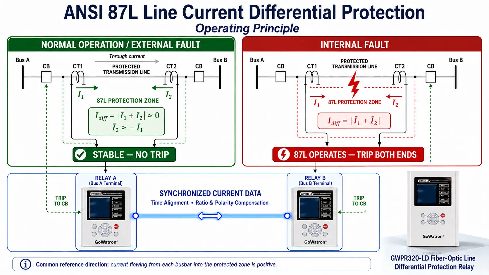
- Line current differential protection (ANSI 87L) settings should be based on the relay algorithm, line charging current, CT performance and power-system short-circuit calculation results.
- The following settings are expressed in per-unit values based on the relay rated current\( I_{\mathrm{n}} \)and apply to protection relays with a rated current input of 1 A or 5 A. If the relay settings are entered in primary or secondary amperes, the values must be converted according to the CT ratio and the relay instruction manual.
- The definitions of differential current, restraint current, percentage slope and characteristic break point may vary among protection relays. The following ranges are intended only as initial engineering reference values and are not uniform setting values prescribed by IEC or ANSI. Final settings must be based on the differential operating characteristic of the specific relay.
1. Minimum Differential Pickup Current
The minimum differential pickup current is denoted by:
\[ I_{\mathrm{op.min}} \]
This setting must remain above the maximum unbalance current that may occur during normal operation and external faults while providing adequate operating sensitivity for the minimum internal line fault.
The preliminary stability criterion is:
\[ I_{\mathrm{op.min}} \geq K_{\mathrm{rel}}I_{\mathrm{unb.max}} \]
where:
- \( I_{\mathrm{unb.max}} \) is the maximum unbalance current caused by CT errors, relay measurement errors, data-synchronization errors and other inaccuracies;
- \( K_{\mathrm{rel}} \)is the reliability factor.
If line charging-current compensation is not enabled, the following condition should also be satisfied:
\[ I_{\mathrm{op.min}} \geq K_{\mathrm{ch}}I_{\mathrm{ch.max}} \]
where:
- \( I_{\mathrm{ch.max}} \) is the maximum line charging current at the highest operating voltage;
- \( K_{\mathrm{ch}} \) is a reliability factor that accounts for line-capacitance data errors and switching transients.
The steady-state RMS value of the charging current per phase may be estimated as:
\[ I_{\mathrm{ch}} = 2\pi fC_{\mathrm{total}} \frac{U_{\mathrm{LL}}}{\sqrt{3}} \]
where:
- \( I_{\mathrm{ch}} \) is the steady-state RMS value of the charging current per phase;
- \( f \)is the power-system frequency;
- \( C_{\mathrm{total}} \) is the total phase-to-earth capacitance per phase;
- \( U_{\mathrm{LL}} \) is the RMS line-to-line voltage.
An initial engineering reference range is:
\[ I_{\mathrm{op.min}} = (0.2\sim0.5)I_{\mathrm{n}} \]
As a general guide:
- For short overhead lines with well-matched CTs at both ends, an initial setting of \(0.2\sim0.3I_{\mathrm{n}}\) may be considered.
- For long high-voltage lines, the setting should be calculated using the actual line charging current.
- Cable circuits have relatively high phase-to-earth capacitance, so their charging current must be carefully checked.
- When reliable charging-current compensation is enabled, a lower pickup setting may be applied within the range permitted by the relay.
2. Sensitivity Check
Under the minimum system operating condition, the sensitivity factor for the minimum internal line fault may be expressed as:
\[ K_{\mathrm{sen}} = \frac{ I_{\mathrm{diff,int.min}} }{ I_{\mathrm{op.threshold}} \left( I_{\mathrm{rest,int.min}} \right) } \]
where:
- \( I_{\mathrm{diff,int.min}} \) is the differential current produced by the minimum internal fault used for the sensitivity check under the minimum system operating condition;
- \( I_{\mathrm{rest,int.min}} \)is the restraint current corresponding to that minimum internal fault;
- \( I_{\mathrm{op.threshold}}(I_{\mathrm{rest,int.min}}) \) is the actual operating threshold determined from the relay’s percentage-restraint characteristic at the corresponding restraint current.
The actual operating threshold is not necessarily equal to \( I_{\mathrm{op.min}} \). When the restraint current exceeds the first break point, the actual operating threshold should be calculated from the relay’s percentage-restraint characteristic.
The minimum required sensitivity factor should be determined according to the project specification and the relay instruction manual.
3. Percentage-Restraint Characteristic Settings
The percentage-restraint characteristic maintains stability during external faults despite CT errors and CT saturation.
First Restraint Break Point
The first restraint break-point current is denoted by:
\( I_{\mathrm{rest,1}} \)
An initial engineering reference range is:
\[ I_{\mathrm{rest,1}} = (0.5\sim1.0)I_{\mathrm{n}} \]
Below the first break point, the operating threshold is generally determined by the minimum differential pickup current. Above the first break point, the operating threshold increases with the restraint current.
If the relay provides an adjustable second restraint break point \( I_{\mathrm{rest,2}} \), its setting should be determined from the relay operating characteristic, the maximum external through-fault current and the risk of CT saturation. No universal reference range is recommended.
Percentage-Restraint Slopes
For a dual-slope percentage-restraint characteristic, the following initial engineering ranges may be considered:
\[ K_1=20\%\sim40\% \]
\[ K_2=50\%\sim80\% \]
where:
- \( K_1 \) is Slope 1, which balances internal-fault sensitivity and stability during ordinary external faults;
- \( K_2 \)is Slope 2, which improves stability during high through-fault currents and severe CT saturation.
Normally:
\[ K_2>K_1 \]
A typical dual-slope operating threshold may be expressed as:
\[ I_{\mathrm{op.threshold}} = \begin{cases} I_{\mathrm{op.min}}, & I_{\mathrm{rest}} \leq I_{\mathrm{rest,1}} \\[6pt] I_{\mathrm{op.min}} + K_1 \left( I_{\mathrm{rest}}-I_{\mathrm{rest,1}} \right), & I_{\mathrm{rest,1}} < I_{\mathrm{rest}} \leq I_{\mathrm{rest,2}} \\[6pt] I_{\mathrm{th,2}} + K_2 \left( I_{\mathrm{rest}}-I_{\mathrm{rest,2}} \right), & I_{\mathrm{rest}} > I_{\mathrm{rest,2}} \end{cases} \]
where:
\[ I_{\mathrm{th,2}} = I_{\mathrm{op.min}} + K_1 \left( I_{\mathrm{rest,2}}-I_{\mathrm{rest,1}} \right) \]
The differential element operates when:
\[ I_{\mathrm{diff}} > I_{\mathrm{op.threshold}} \]
The definition of restraint current and the shape of the operating characteristic vary among protection relays. Some relays use two break points, dynamic restraint, the Alpha Plane or other differential algorithms. Final slope and break-point settings must therefore be determined from the operating characteristic of the specific relay.
4. Zero-Sequence Differential Protection Setting
If the relay provides a dedicated zero-sequence current differential element, also referred to by some manufacturers as an earth-current differential element, its pickup setting may be denoted by:
\[ I_{0,\mathrm{diff.set}} \]
An initial engineering reference range is:
\[ I_{0,\mathrm{diff.set}} = (0.1\sim0.3)I_{\mathrm{n}} \]
The zero-sequence current calculated from the three-phase currents is:
\[ \dot I_0 = \frac{ \dot I_{\mathrm{A}} + \dot I_{\mathrm{B}} + \dot I_{\mathrm{C}} }{3} \]
The residual current, equal to three times the zero-sequence current, is:
\[ 3\dot I_0 = \dot I_{\mathrm{A}} + \dot I_{\mathrm{B}} + \dot I_{\mathrm{C}} \]
When setting the zero-sequence differential element, it is essential to confirm whether the relay setting is based on \( I_0 or 3I_0 \). These quantities differ by a factor of three and must not be confused.
The final setting should also be checked against:
the maximum zero-sequence unbalance current during normal operation;
- three-phase CT measurement errors;
- phase unbalance in line charging currents;
- CT saturation during external earth faults;
- the minimum internal earth-fault current;
- the effect of earth-fault resistance.
5. Summary of Initial Setting Values
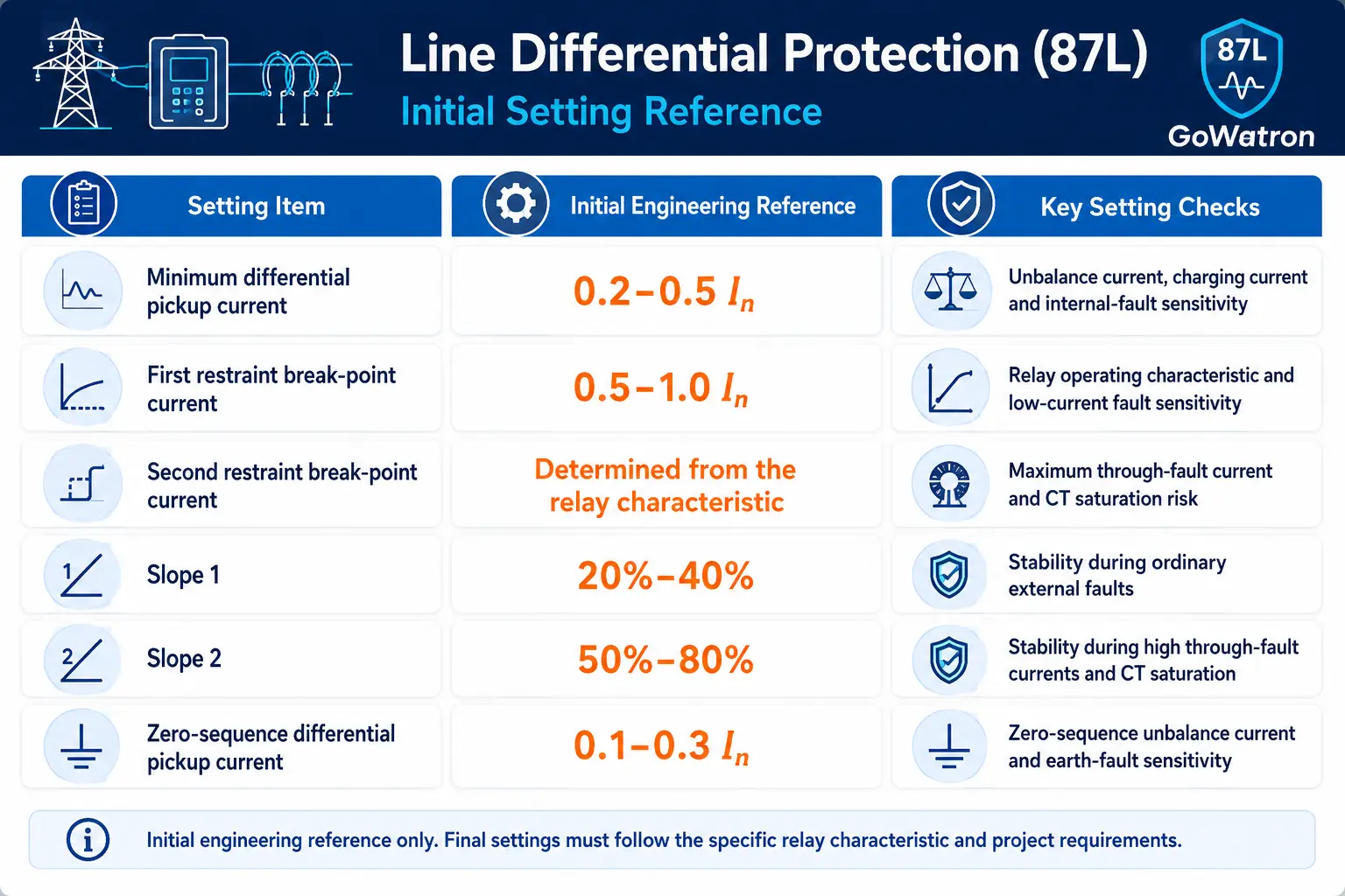
The values above are intended only for preliminary setting selection. Final settings must be checked for both stability and sensitivity using the line parameters, maximum external short-circuit current, minimum internal fault current, CT transient performance and the instruction manual for the specific protection relay.


