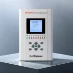
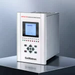

GWPR300-TNE Transformer Non-Electrical Quantity Protection Relay
- The GWPR300-TNE Transformer Non-Electrical Quantity Protection Relay is designed for transformers rated up to and including 132 kV. Built on a high-performance 32-bit microcontroller platform with an integrated DSP and FPU, the relay provides protection processing, output logic, event recording, disturbance recording, and communication with substation supervisory systems. It continuously acquires and evaluates non-electrical quantity signals from the transformer main tank and on-load tap changer and initiates the corresponding trip or alarm outputs.
- The relay is primarily intended for transformer non-electrical quantity protection applications. It can receive signals associated with Buchholz alarm, Buchholz trip, temperature, cooling-system failure, pressure-relief device operation, oil level, and other non-electrical conditions. Trip or alarm outputs are initiated according to the configured logic and time-delay settings to help ensure safe and stable transformer operation.
- The relay supports two Ethernet ports using IEC 60870-5-104, two optional Ethernet ports using IEC 61850, and one RS-485 communication port using Modbus RTU. Supported time-synchronization methods include communication-message synchronization, SNTP, and IRIG-B. The relay also supports a serial dot-matrix printer for printing setting values and event records.




Product Description
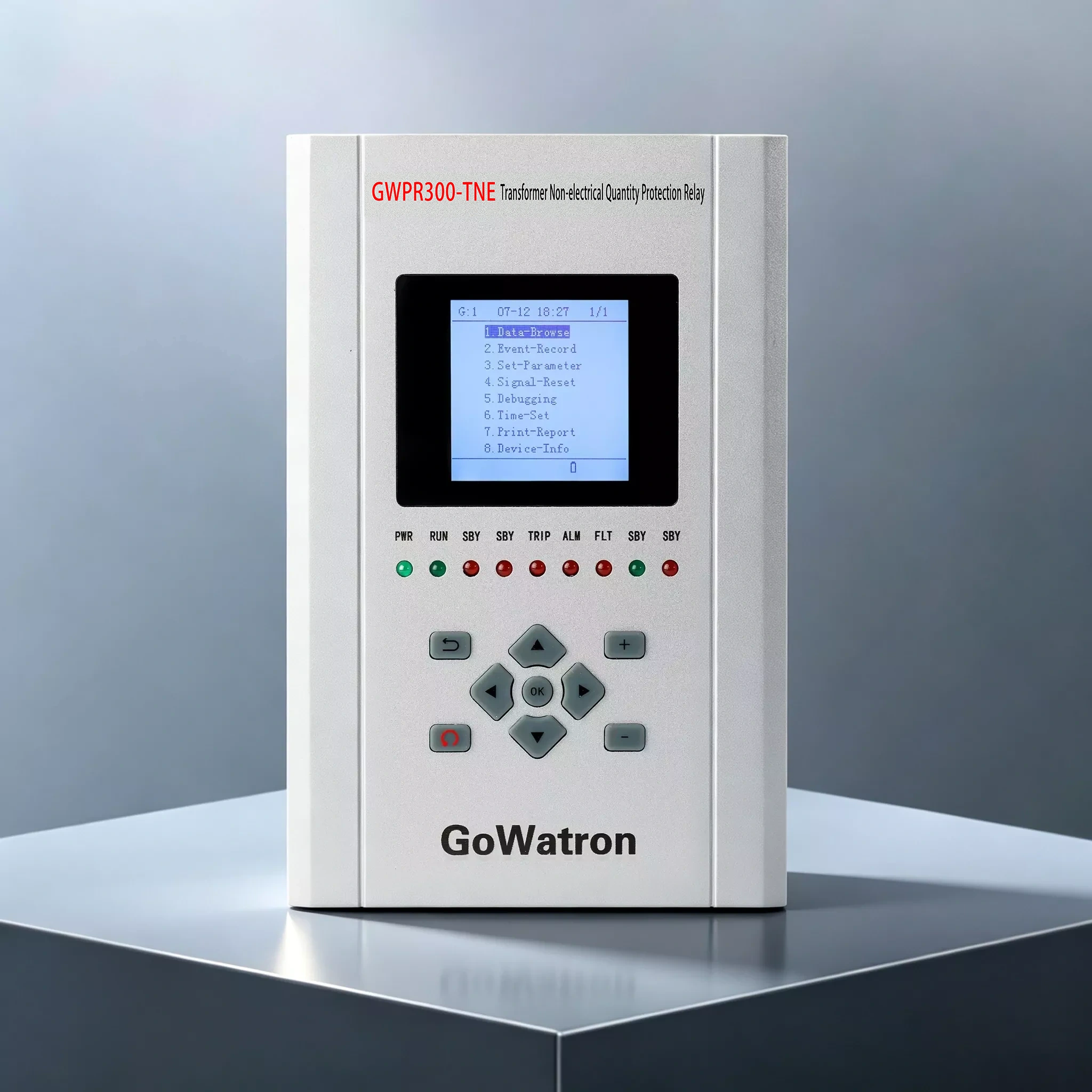
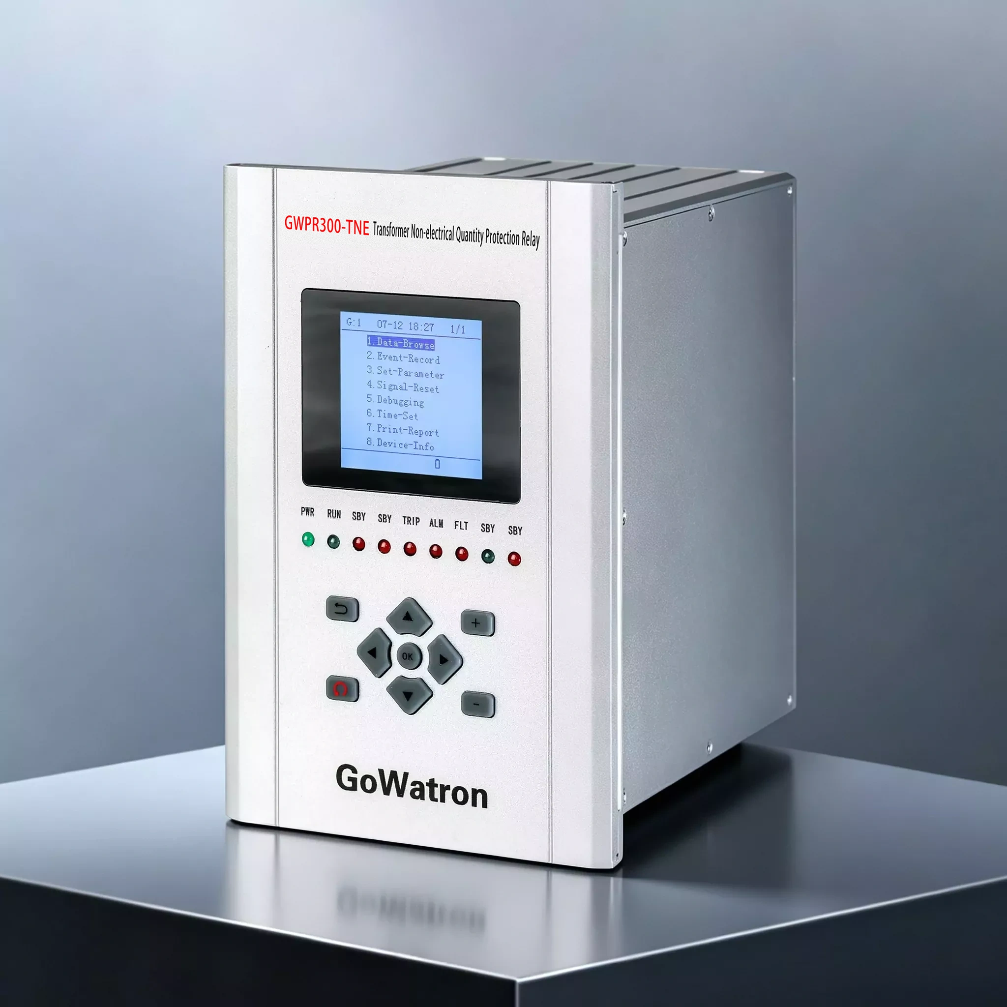
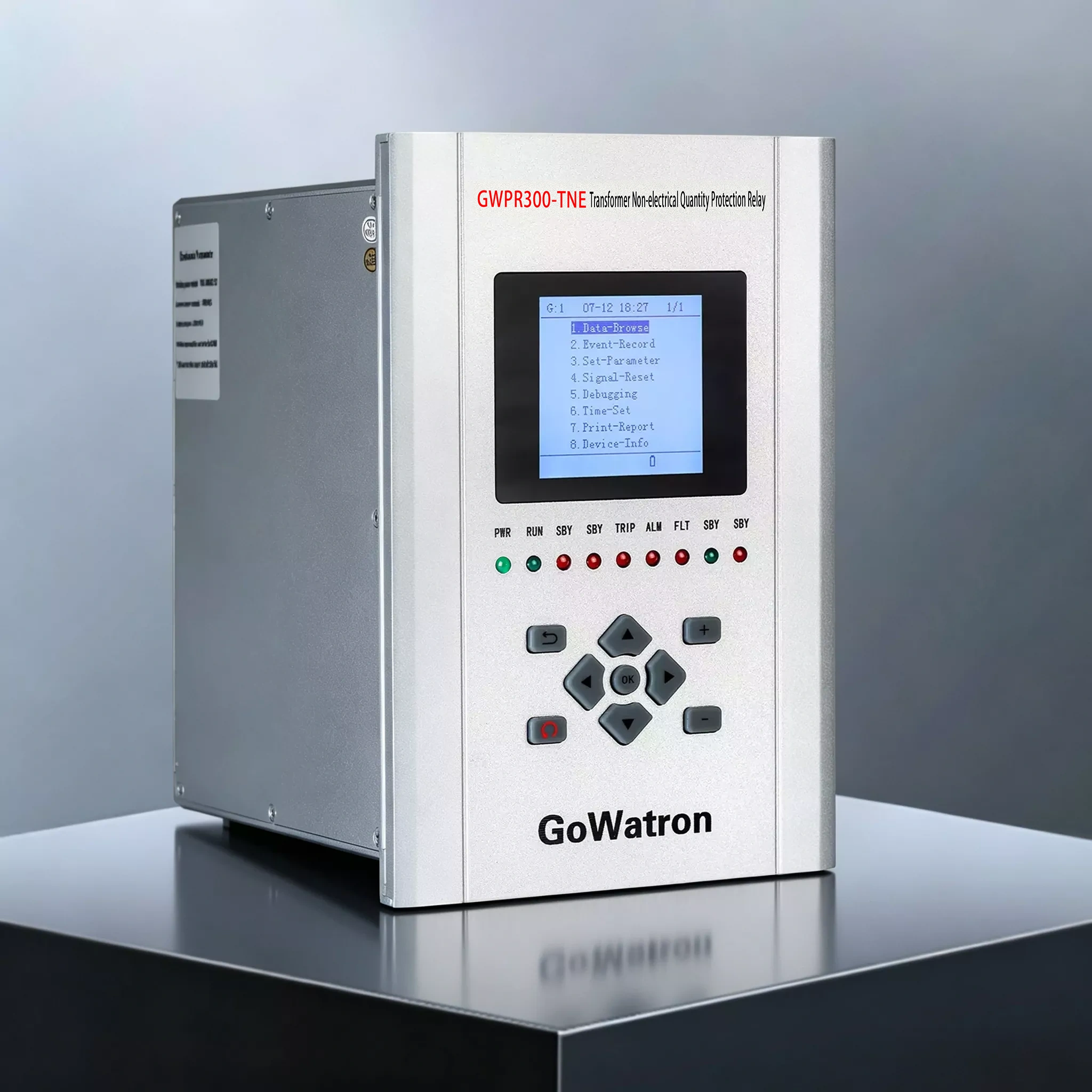
- The GWPR300-TNE features an integrated front panel and a fully enclosed chassis. High-voltage and low-voltage circuits are strictly separated, while both hardware and software incorporate anti-interference measures to provide strong electromagnetic compatibility and adaptability to demanding site conditions. Its flexible hardware architecture and internal high-speed bus facilitate expansion and maintenance.
- The relay is equipped with a user-friendly human–machine interface that supports an LCD, push-button operation, local commissioning, event-record review, and report printing. It also provides a wide range of external interfaces, including dual Ethernet ports, an RS-485 serial communication port, and an IRIG-B time-synchronization interface, meeting the communication and integration requirements of substation automation systems.
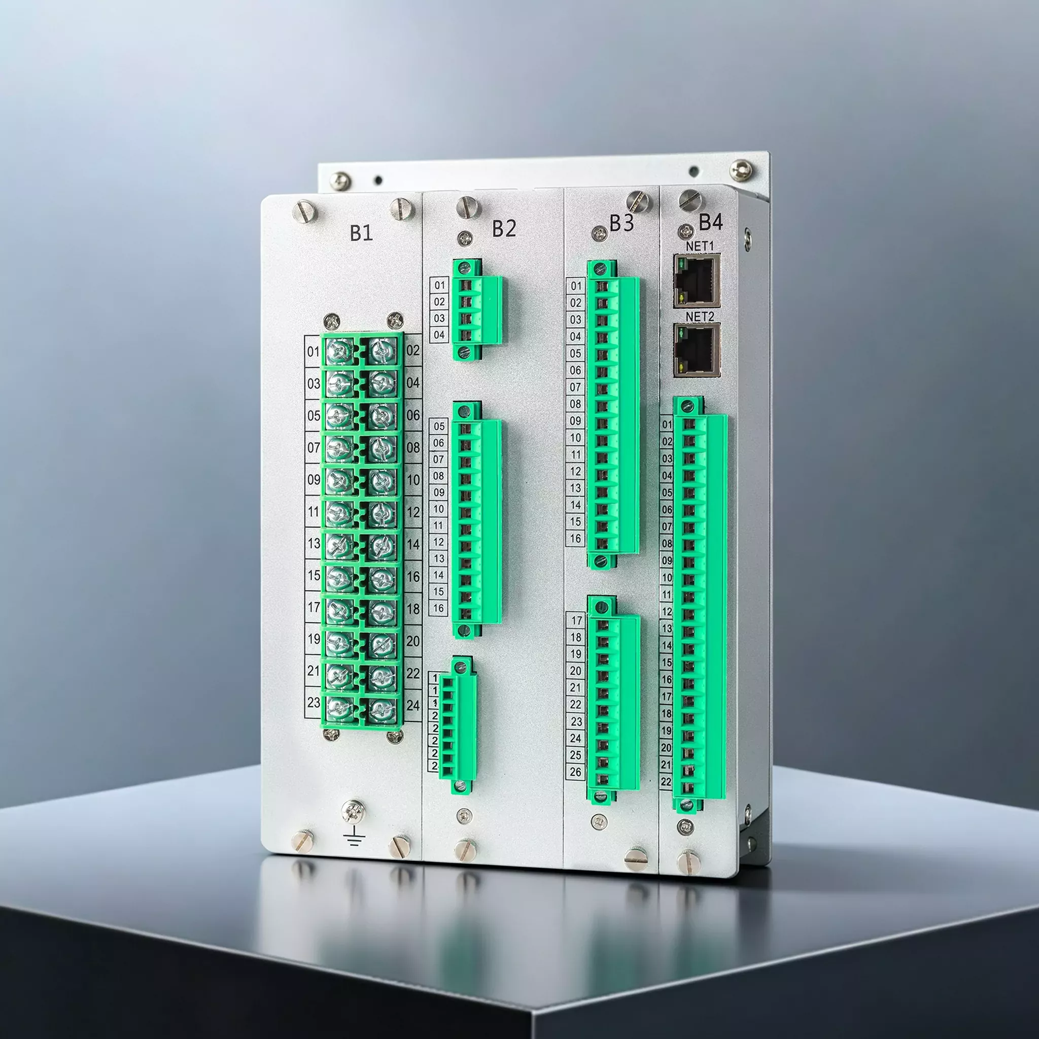
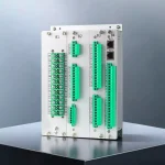
- The device consists of an AC input module (B1), power-supply module (B2), binary output module (B3), binary input module (B4), CPU module, and human–machine interface module. The B3 module provides 11 protection operation outputs and two signal outputs. The B4 module provides 21 binary inputs and two Ethernet ports, meeting the requirements of transformer non-electrical quantity protection, control, and monitoring.
Main Functions
1. Non-Electrical Quantity Protection Functions
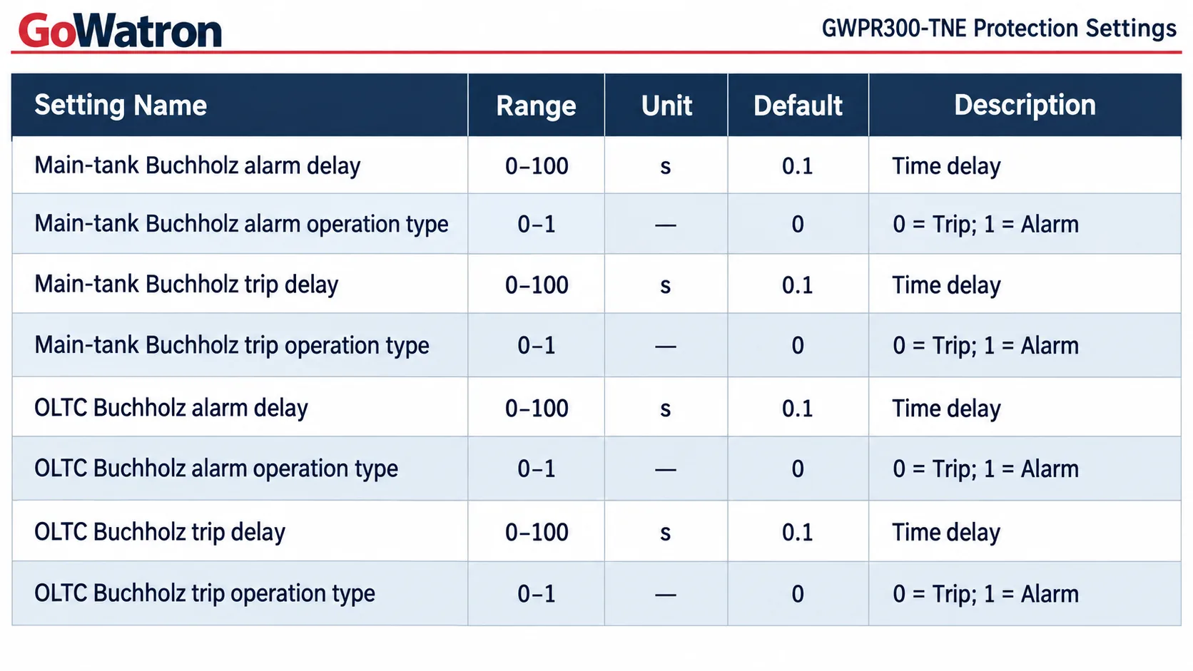
The relay provides ten non-electrical quantity protection elements. Each element can be configured through the settings as either “Trip” or “Alarm” and has an independently configurable time delay. The protection functions and corresponding ANSI device numbers, where applicable, are as follows:
- (ANSI 63) Main-tank Buchholz alarm (Trip/Alarm)
- (ANSI 63) Main-tank Buchholz trip (Trip/Alarm)
- (ANSI 63) OLTC (on-load tap changer) Buchholz alarm (Trip/Alarm)
- (ANSI 63) OLTC Buchholz trip (Trip/Alarm)
- (ANSI 26) High temperature (Trip/Alarm)
- (ANSI 26) Very high temperature (Trip/Alarm)
- Cooling-system failure (Trip/Alarm)
- (ANSI 63) Pressure-relief device operation (Trip/Alarm)
- (ANSI 26) Abnormal oil temperature (Trip/Alarm)
- (ANSI 71) Abnormal oil level (Trip/Alarm)
Using the main-tank Buchholz alarm function as an example, when the protection element and its software enable are both activated, the corresponding non-electrical quantity input signal is detected, the correct operation type is selected, and the signal persists for the configured time delay, the relay immediately initiates the assigned trip output or energizes the alarm signal relay. The corresponding message is displayed on the LCD, and the operation or alarm indicator on the front panel illuminates.
2. Control and Monitoring Functions
- Supports 21 externally powered binary inputs (AC/DC 220 V, DC 100 V, or DC 48 V; the required voltage must be specified when ordering)
- Supports 13 independent relay outputs
- Supports one device power-failure signal output
3. Recording Functions
- Protection events: Records the event time, operating value, and protection function name; stores up to 128 records
- Alarm events: Records the alarm time, operating value, and protection function name; stores up to 128 records
- Binary input events: Records changes in binary input status; stores up to 128 records
- Operation logs: Records operations such as setting changes and protection function enabling or disabling; stores up to 128 records
- Self-supervision events: Records events generated by the device’s self-supervision system; stores up to 32 records
Main Parameters
1. Environmental Conditions
- Operating temperature: −40 to +70°C
- Storage and transportation temperature: −40 to +80°C
- Relative humidity: 5% to 90%, non-condensing
- 2. Rated Electrical Parameters
Auxiliary power supply:
- AC supply: AC 100–264 V; 50 Hz ±0.5 Hz; total harmonic distortion not exceeding 15%
- DC supply: DC 100–264 V; ripple factor not exceeding 5%
- Power consumption:
- During normal operation with a DC auxiliary supply: ≤10 W
- During protection operation: ≤15 W
3. Main Technical Specifications
- Binary input time resolution: ≤1 ms
- Relay outputs:
- Output type: Potential-free contacts
- Contact rating: 8 A at 250 V AC; 8 A at 30 V DC
- Operating time: ≤8 ms
- Reset time: ≤5 ms
4. Electromagnetic Compatibility
- The relay is designed to withstand electrostatic discharge, electrical fast transients, radiated radio-frequency electromagnetic fields, surges, power-frequency magnetic fields, damped oscillatory magnetic fields, pulsed magnetic fields, and conducted disturbances induced by radio-frequency fields. It also complies with the applicable conducted-emission and radiated-emission limits.
5. Insulation Performance
- Insulation resistance: Not less than 100 MΩ between each conductive circuit and earth and between electrically isolated circuits
- Dielectric withstand: Circuits with a rated insulation voltage of 63–250 V can withstand a 2.0 kV power-frequency dielectric test for 1 minute. Circuits with a rated insulation voltage of ≤63 V can withstand a 500 V power-frequency dielectric test for 1 minute
- Impulse voltage withstand: Circuits with a rated insulation voltage of 63–250 V can withstand a standard 1.2/50 μs lightning impulse test with an open-circuit test voltage of 5 kV. Circuits with a rated insulation voltage of ≤63 V can withstand a standard 1.2/50 μs lightning impulse test with an open-circuit test voltage of 1 kV
6. Mechanical Performance
- The relay can withstand Severity Class I vibration, shock, and bump tests. After testing, its mechanical structure remains free from damage, loosening, or component detachment, while its protection, control, and monitoring performance continues to meet the applicable requirements.
7. Example Protection Settings
Applications
- Non-electrical quantity protection of transformers rated up to and including 132 kV
- Main-tank protection of power transformers in substations
- Non-electrical quantity protection of transformers equipped with on-load tap changers
- Applications requiring the acquisition of signals associated with Buchholz alarm, Buchholz trip, temperature, cooling-system failure, pressure-relief device operation, oil level, and other non-electrical conditions
- Substation automation systems requiring IEC 60870-5-104 and Modbus RTU communication or optional IEC 61850 communication
- Transformer protection applications requiring local printing, event recording, disturbance recording, and communication with supervisory systems
Appendix: ANSI Device Number Descriptions
- ANSI 63: Pressure switch or detector. For this product, it is applied to the main-tank Buchholz alarm, main-tank Buchholz trip, OLTC Buchholz alarm, OLTC Buchholz trip, and pressure-relief device operation signals
- ANSI 26: Apparatus thermal device. For this product, it is applied to high-temperature, very-high-temperature, and abnormal oil-temperature signals received from external transformer temperature-monitoring devices. ANSI 49 may instead be used when a relay provides transformer thermal protection based on measured quantities or a thermal model
- ANSI 71: Liquid-level switch. For this product, it is applied to the abnormal transformer oil-level signal
- Cooling-system failure: No single ANSI device number universally represents a general transformer cooling-system failure input. Therefore, no ANSI device number is assigned unless the input corresponds to a specifically defined pressure, flow, temperature, or auxiliary-equipment function
Conclusion
- Built on a high-performance hardware platform and incorporating comprehensive protection logic, flexible communication options, and a user-friendly human–machine interface, the GWPR300-TNE Transformer Non-Electrical Quantity Protection Relay provides a reliable non-electrical quantity protection solution for transformers rated up to and including 132 kV. The relay supports multiple binary input voltage levels, communication protocols, and optional functions and can be flexibly configured to meet project-specific requirements.


