Generator Zero-Sequence Voltage Protection (ANSI 59N): Operating Principles, Functions and Setting Calculations
- Generator zero-sequence voltage protection is used for stator earth-fault detection. With dedicated voltage transformer (VT) connections and suitable fault discrimination, a zero-sequence voltage scheme can also provide longitudinal zero-sequence voltage interturn protection.
- These applications use different measurement arrangements and operating criteria. Their protection zones, sensitivity and security must therefore be assessed separately.
1. Operating Principles
1.1 Zero-Sequence Voltage and Residual Voltage
Using fundamental-frequency voltage phasors, zero-sequence voltage is:
\[ \underline{U}_0= \frac{\underline{U}_A+\underline{U}_B+\underline{U}_C}{3} \]
Residual voltage is:
\[ 3\underline{U}_0= \underline{U}_A+\underline{U}_B+\underline{U}_C \]
Where:
- \( \underline{U}_A \), \( \underline{U}_B \) and \\( \underline{U}_C \)are the phase-to-earth voltage phasors.
- \( \underline{U}_0 \) is the zero-sequence voltage.
- \( 3\underline{U}_0 \) is the residual voltage.
Under balanced fundamental-frequency conditions, the phasor sum is approximately zero.
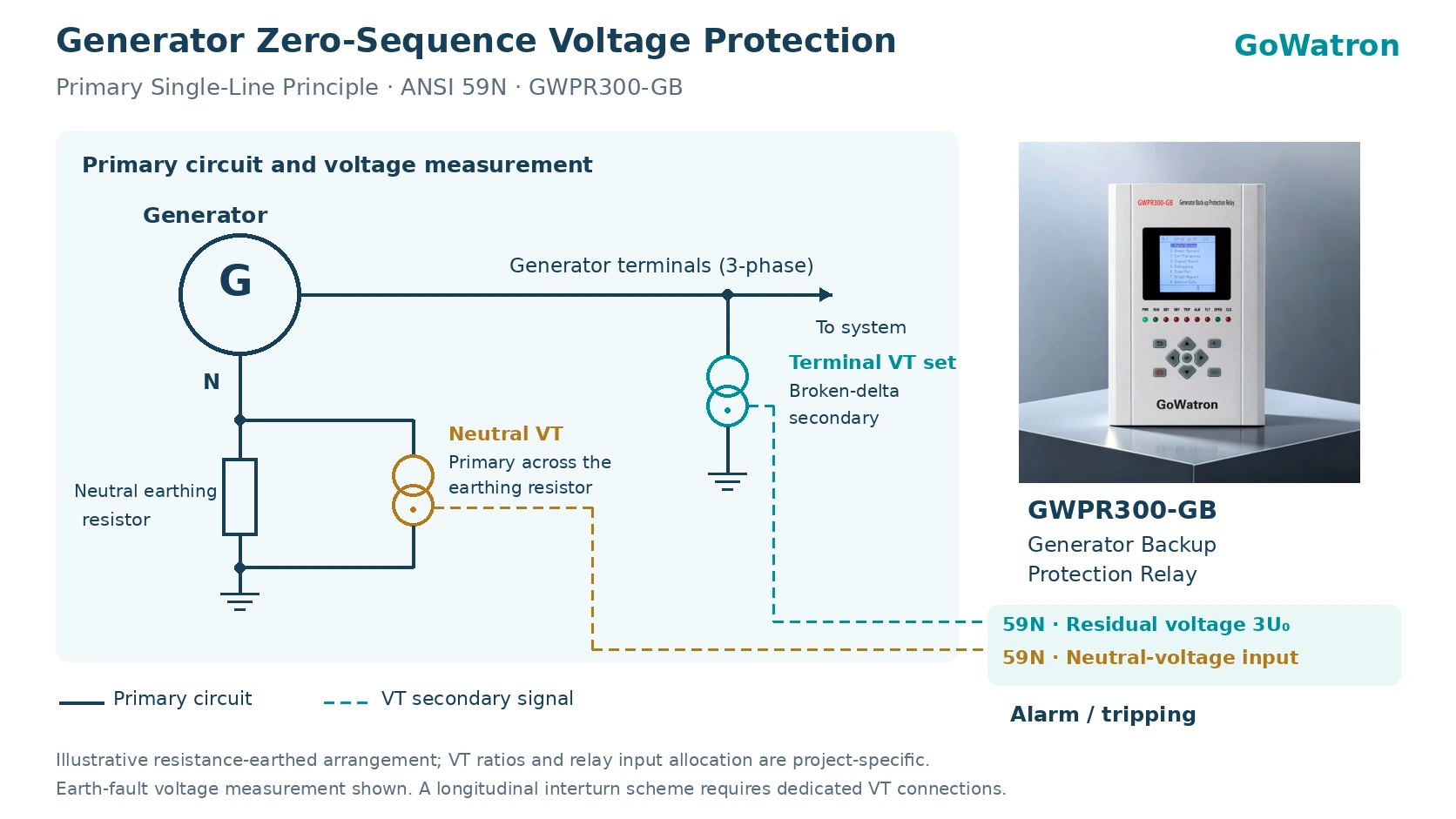
The protection may obtain residual voltage from a broken-delta winding, or it may calculate it from three phase-to-earth voltage inputs. A neutral-voltage scheme measures voltage through the generator neutral earthing circuit.
The quantities \( U_0 \), \( 3U_0 \)and neutral-point voltage must not be treated as interchangeable settings. Their scaling depends on the VT connections, transformation ratios and relay measurement definitions.
1.2 Stator Earth-Fault Protection
A stator earth fault connects part of the winding to earth. Depending on the neutral earthing arrangement, the fault produces neutral displacement and an increase in the measured neutral or residual voltage.
The protection detects earth faults in the stator winding and in electrically connected equipment within its protection zone.
The protection zone depends on the primary system connections and earthing arrangement.
A simplified definite-time overvoltage criterion is:
\[ U_{\mathrm{meas}}>U_{\mathrm{set}} \]
continuously for the operating time delay:
\[ t\geq t_{\mathrm{set}} \]
Where:
- \( U_{\mathrm{meas}} \) is the magnitude of the voltage quantity used by the element.
- \( U_{\mathrm{set}} \)is the pickup setting.
- \( t_{\mathrm{set}} \)is the operating time delay.
Operation also requires the element to be enabled, all applicable permission conditions to be satisfied and no applicable blocking condition to be present.
1.3 Neutral-End Blind Zone
- Fundamental-frequency zero-sequence voltage protection has a blind zone near the generator neutral.
- An earth fault close to the neutral generally produces less fundamental neutral voltage than a fault close to the generator terminals. The resulting voltage may remain below the pickup setting.
- Where full stator winding coverage is required, an appropriate complementary scheme is necessary. Depending on the application, this may use third-harmonic quantities or an injection-based protection method.
- A third-harmonic scheme must be assessed over the relevant generator operating range, because its suitability cannot be inferred solely from the availability of a third-harmonic voltage measurement.
1.4 Longitudinal Zero-Sequence Voltage Interturn Protection
A stator interturn fault short-circuits turns within a winding. The fault can produce a damaging circulating current without initially creating a large current difference at the winding terminals.
Longitudinal zero-sequence voltage interturn protection detects the winding voltage imbalance using a dedicated VT arrangement.
Its measured quantity differs from ordinary terminal residual voltage used for earth-fault protection. A complete scheme requires:
- Suitable VT connections.
- Correct ratios and polarities.
- Adequate internal-fault sensitivity.
- External-fault discrimination.
- VT circuit supervision.
- Appropriate operating delays and output logic.
The presence of an ANSI 59N element alone does not establish a complete longitudinal zero-sequence voltage interturn protection scheme.
1.5 ANSI Designations
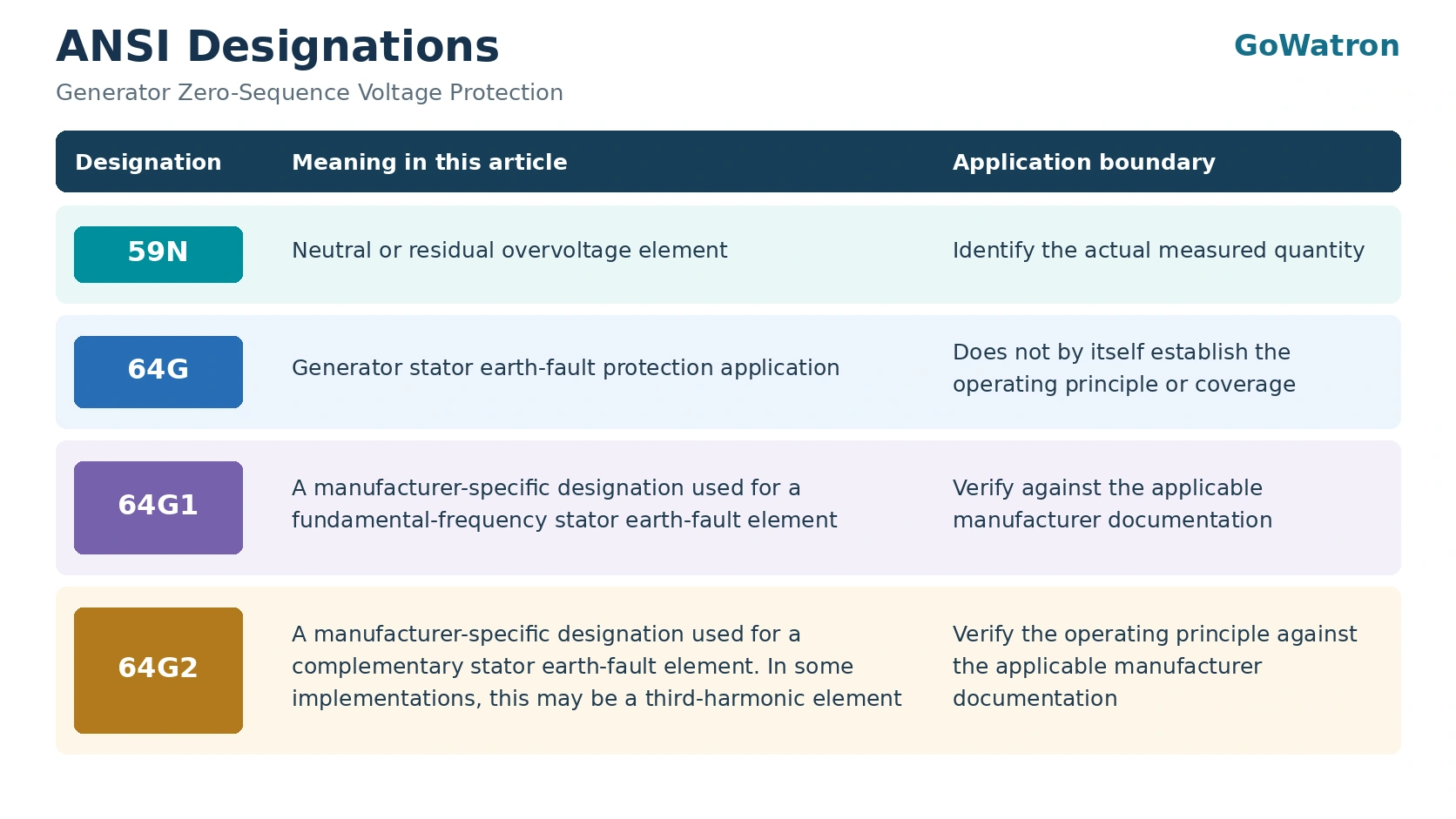
- In a documented combined scheme, a fundamental-frequency neutral overvoltage element and a suitable third-harmonic element may provide complementary stator winding coverage.
- The designations 64G1 and 64G2 must be interpreted according to the relevant manufacturer documentation. They must not be assigned to the GWPR300-GB without supporting technical information.
2. Main Functions
2.1 Detecting Stator Earth Faults
Neutral or residual overvoltage protection provides sensitivity to earth faults that produce a sufficient voltage response in the selected measurement circuit.
Its effectiveness depends on:
- The generator neutral earthing arrangement.
- Fault location and resistance.
- VT connections and transformation ratios.
- Pickup setting and operating delay.
- The generator operating condition.
2.2 Detecting Interturn Faults
- A dedicated longitudinal zero-sequence voltage interturn protection scheme can complement current-based protection where an interturn fault produces a detectable winding voltage imbalance.
- The scheme must distinguish internal winding faults from external disturbances and VT circuit abnormalities.
2.3 Complementing Generator Differential Protection
- Generator current differential protection, designated 87G, and voltage-based protection respond to different electrical quantities.
- Zero-sequence voltage protection can complement differential protection for fault conditions that produce a significant neutral or residual voltage but limited differential current.
2.4 Initiating Alarm or Tripping
- The output action depends on the approved protection philosophy and the role of the element.
- Alarm and tripping assignments must follow the project design.
- Protection reset does not automatically authorise generator restart or breaker closing. Reset and restart must be treated separately: element reset follows the configured protection logic, while restart remains subject to fault investigation, plant operating procedures and the required interlocks.
3. Setting Calculations
3.1 Confirm the Measurement Basis
Before calculating settings, confirm:
- Whether the element uses \(U_0\), \(3U_0\), neutral-point voltage or a dedicated winding voltage quantity.
- Whether the quantity is directly measured or calculated.
- The effective transformation ratio.
- Whether settings are entered in primary volts, secondary volts or per-unit values.
- The frequency component used by the element.
3.2 Voltage Conversion
For an effective primary-to-secondary voltage ratio \( K_U \):
\[ U_{\mathrm{sec}}= \frac{U_{\mathrm{pri}}}{K_U} \]
Where:
\( U_{\mathrm{pri}} \) is the primary voltage corresponding to the measured quantity.
\( U_{\mathrm{sec}} \) is the corresponding secondary voltage.
\( K_U \) is the effective transformation ratio.
The ratio must correspond to the actual measurement circuit. For a broken-delta winding or an earthing transformer circuit, the phase-voltage VT ratio must not be used without checking its applicability.
3.3 Security Requirement
A conceptual lower limit for the pickup setting is:
\[ U_{\mathrm{set}} \geq K_{\mathrm{rel}}\times U_{\mathrm{unb,max}} \]
Where:
\( K_{\mathrm{rel}} \) is the security margin factor.
\( U_{\mathrm{unb,max}} \)is the maximum assessed unbalance voltage in the measurement channel under conditions for which the element must remain stable, including relevant measurement errors and external-disturbance effects.
For this calculation, \(U_{\mathrm{unb,max}}\) must represent the relevant non-operating conditions. It must not be limited to normal operating unbalance if other conditions determine the security requirement.
3.4 Sensitivity Requirement
The sensitivity factor is:
\[ K_{\mathrm{sen}}= \frac{U_{\mathrm{fault,min}}}{U_{\mathrm{set}}} \]
Where:
\( U_{\mathrm{fault,min}} \) is the minimum assessed voltage for the fault conditions that must be detected.
\( U_{\mathrm{set}} \) is the pickup setting.
To satisfy the required sensitivity:
\[ K_{\mathrm{sen}}\geq K_{\mathrm{sen,req}} \]
Therefore:
\[ U_{\mathrm{set}} \leq \frac{U_{\mathrm{fault,min}}}{K_{\mathrm{sen,req}}} \]
The conceptual setting range is:
\[ K_{\mathrm{rel}}U_{\mathrm{unb,max}} \leq U_{\mathrm{set}} \leq \frac{U_{\mathrm{fault,min}}}{K_{\mathrm{sen,req}}} \]
All voltages must use the same measurement basis.
If no valid range exists, the scheme requires reassessment. The assessment should examine the measurement arrangement, required coverage, disturbance response and protection method.
3.5 Operating Time Delay
Select the operating delay with reference to:
– External-fault clearing times.
– Transient voltage responses.
– Protection coordination.
– Acceptable internal-fault duration.
– Alarm and tripping requirements.
The security margin factor, required sensitivity factor and operating delay must be established through the engineering study. They are not universal relay settings.
3.6 Illustrative Setting Example
Assume that an engineering study has established the following secondary quantities and factors:
\[ U_{\mathrm{unb,max}}=2.0\ \mathrm{V} \]
\[ K_{\mathrm{rel}}=1.5 \]
\[ U_{\mathrm{fault,min}}=12.0\ \mathrm{V} \]
\[ K_{\mathrm{sen,req}}=2.0 \]
The security lower limit is:
\[ U_{\mathrm{set}}\geq1.5\times2.0=3.0\ \mathrm{V} \]
The sensitivity upper limit is:
\[ U_{\mathrm{set}}\leq\frac{12.0}{2.0}=6.0\ \mathrm{V} \]
The resulting conceptual setting range is:
\[ 3.0\ \mathrm{V}\leq U_{\mathrm{set}}\leq6.0\ \mathrm{V} \]
For an illustrative pickup setting of \(4.0\ \mathrm{V}\):
\[ K_{\mathrm{sen}}=\frac{12.0}{4.0}=3.0 \]
The calculated sensitivity factor exceeds the assumed requirement of \( 2.0 \).
This example demonstrates the calculation method. It is not a recommended GWPR300-GB setting.
3.7 Approximate Blind-Zone Assessment
For a simplified low-resistance earth-fault model:
\[ U_{\mathrm{N,pri}}\approx xU_{\mathrm{ph}} \]
Therefore:
\[ x_{\min}\approx \frac{U_{\mathrm{N,pri,set}}}{U_{\mathrm{ph}}} \]
Where:
\( U_{\mathrm{N,pri}} \) is the fundamental neutral voltage on a primary basis.
\( U_{\mathrm{N,pri,set}} \)is the pickup setting referred to the primary neutral-voltage basis.
\( U_{\mathrm{ph}} \)is the generator phase voltage.
\( x \) is the fractional winding distance from the neutral.
\( x_{\min} \) is the approximate minimum detectable winding position measured from the neutral.
The corresponding idealised winding coverage is:
\[ C\approx(1-x_{\min})\times100\% \]
These expressions explain the neutral-end blind zone. Actual coverage requires assessment of fault resistance, earthing impedance, capacitances and operating voltage.
4. Summary Comparison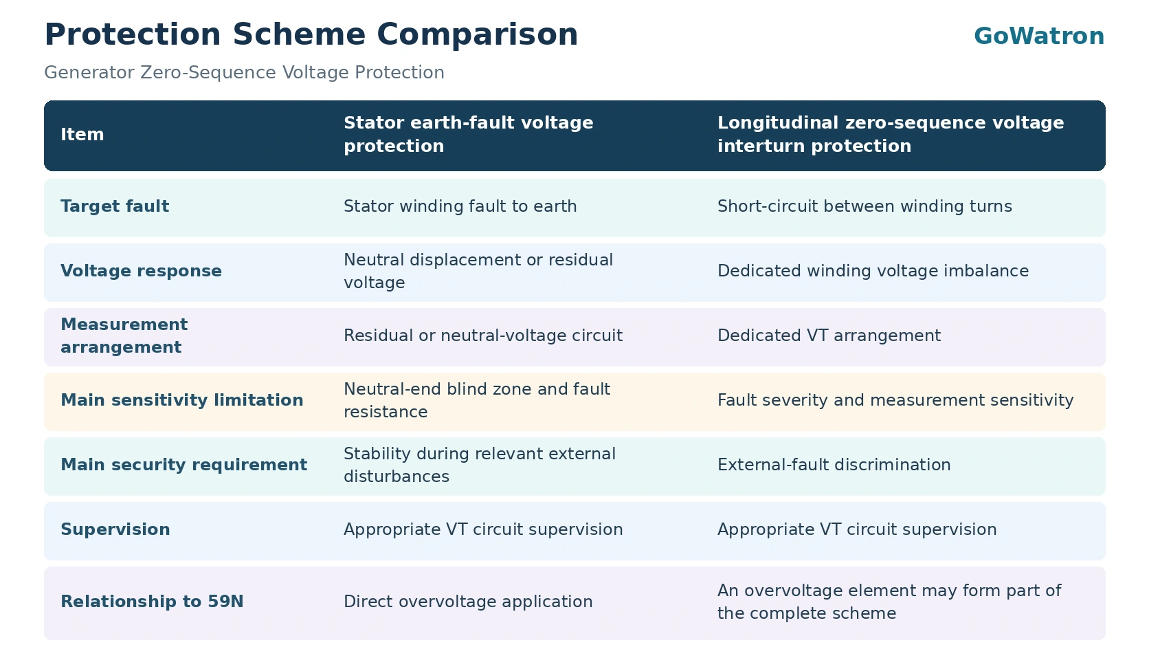
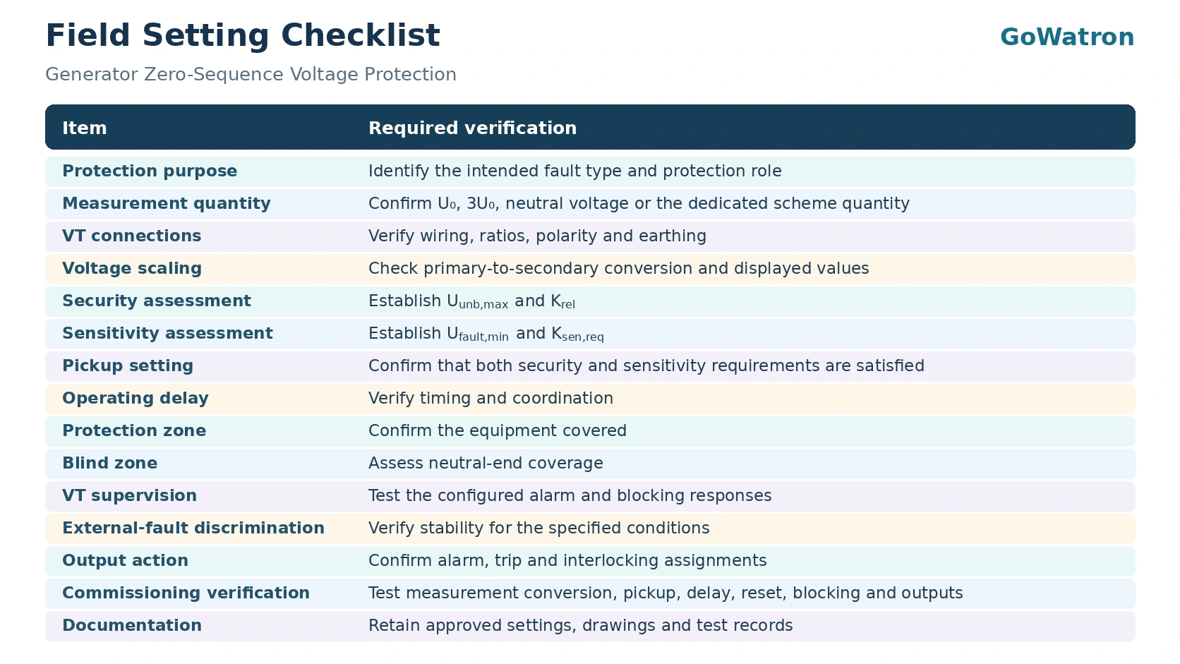
5. Field Setting Checklist
6. GWPR300-GB Application
6.1 Published Protection Functions
The GoWatron GWPR300-GB Generator Backup Protection Relay has the following relevant functions listed in its published product information:
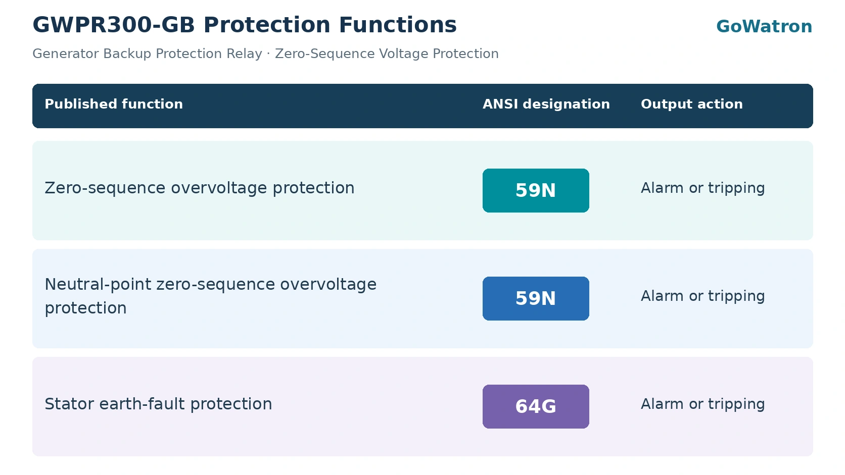 he 59N rows identify the published voltage elements. The 64G row identifies the published stator earth-fault protection application. The relationship between these entries should be verified against the applicable relay documentation.
- The 64G designation is retained as the published application designation. As noted in Section 1.5, this designation does not by itself establish the operating principle or the coverage achieved.
- The published product information does not establish a combined fundamental-frequency and third-harmonic protection scheme, nor does it establish 100% stator winding coverage.
6.2 Stator Earth-Fault Application
The GWPR300-GB can be incorporated into a generator protection scheme using its published zero-sequence and neutral-point overvoltage functions.
For the installed configuration, verify:
- The input used by each element.
- The definition and scaling of the measured voltage.
- Pickup settings and operating delays.
- Permission and blocking conditions.
- Alarm and tripping outputs.
- Protection coverage and any neutral-end blind zone.
6.3 Longitudinal Zero-Sequence Voltage Interturn Application
- The published GWPR300-GB information lists zero-sequence overvoltage functions, designated ANSI 59N.
- Its application to longitudinal zero-sequence voltage interturn protection requires confirmation of the relay version, VT connections and fault discrimination logic.
6.4 Hardware, Firmware and Commissioning
- Use technical documentation corresponding to the installed hardware and firmware version.
- Commissioning must verify the complete measurement and operating chain, from the VT secondary circuit through voltage scaling and protection logic to the assigned outputs.
- Any claim that the installed configuration provides full stator winding coverage or third-harmonic protection must be supported by technical documentation for that configuration.


