11 kV Medium Voltage Switchgear: Types, Applications and Selection Guide
1. What Is 11 kV Medium Voltage Switchgear?
11 kV medium voltage switchgear is an assembly of switching, protection, measurement and control equipment used to receive and distribute electrical power in an 11 kV network.
It is commonly installed in substations, industrial facilities, power plants, renewable energy projects and commercial distribution systems. Depending on the application, an 11 kV switchgear assembly may include circuit breakers, loadbreak switches, earthing switches, current transformers (CTs), voltage transformers (VTs), protection relays and associated control equipment.
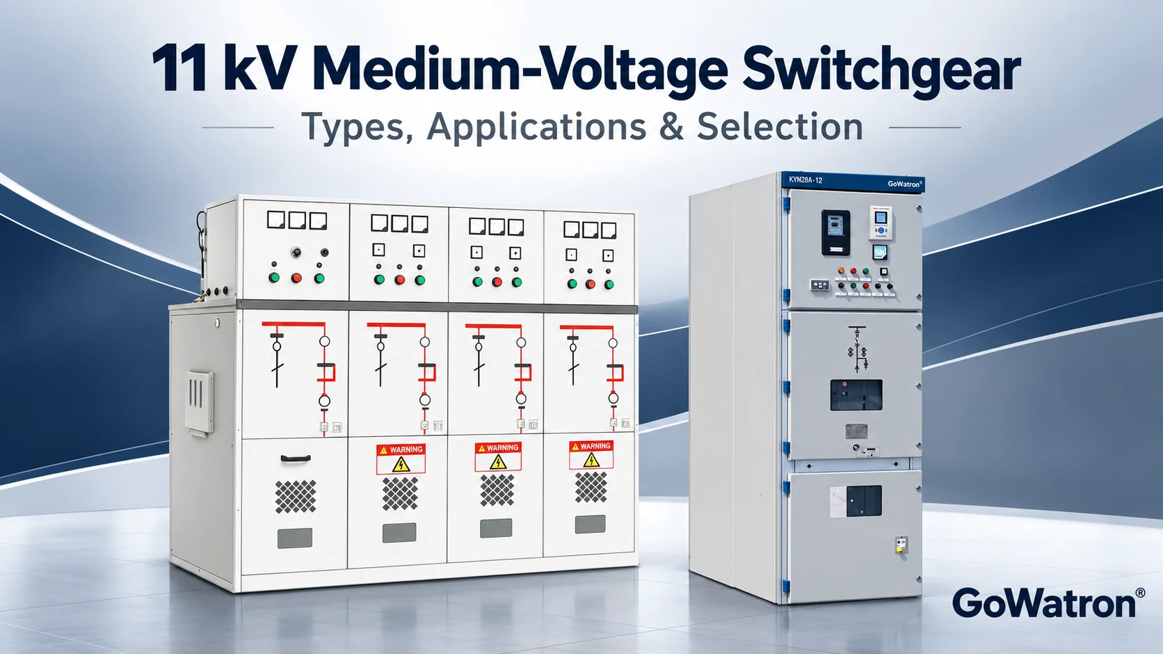
Its main functions include:
- Switching electrical circuits under normal operating conditions;
- Isolating faulty sections of the network;
- Protecting cables, transformers, motors and other equipment;
- Measuring current, voltage, power and energy;
- Providing local and remote control;
- Supporting safe isolation and earthing for maintenance.
In China, similar equipment is commonly described as 10 kV switchgear, because 10 kV is a widely used nominal distribution voltage. For an 11 kV project, equipment with a 12 kV rated voltage is often considered, provided its ratings and insulation performance meet the project requirements.
2. Main Types of 11 kV Medium Voltage Switchgear
11 kV medium voltage switchgear can be classified by its construction, switching device and insulation method. These categories overlap: for example, a ring main unit can be air-insulated, gas-insulated or solid-insulated.
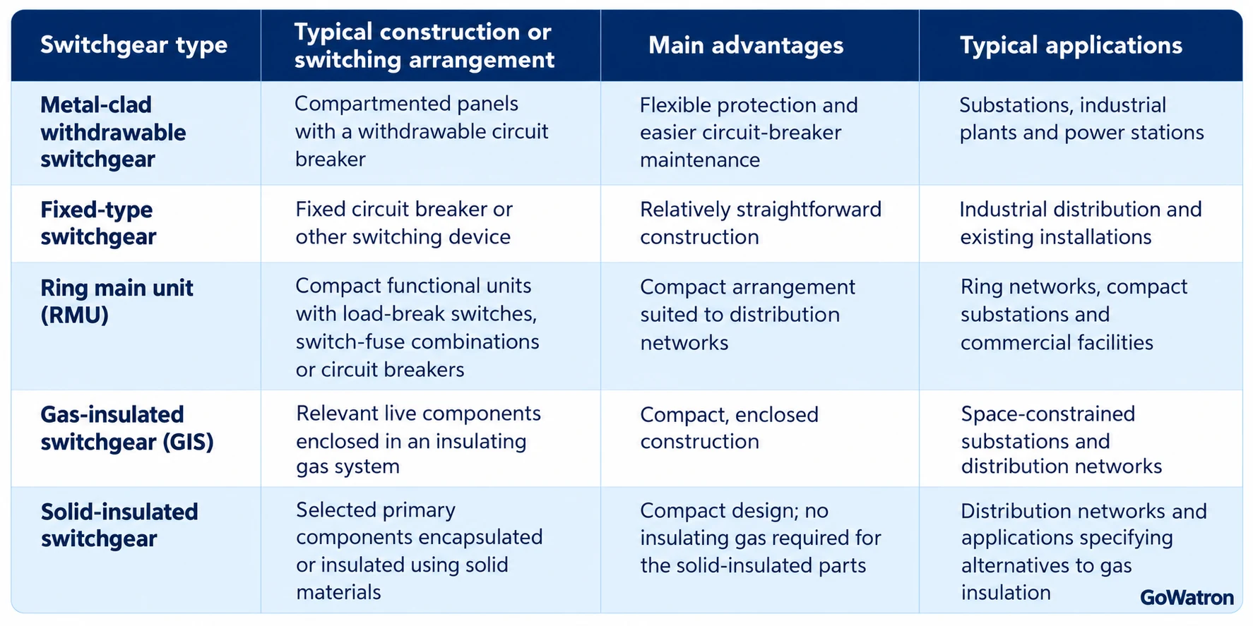
The exact configuration and performance vary by manufacturer and product series. A switchgear type or model name alone does not confirm its short-circuit rating, internal arc classification or protection functions.
3. Metal-Clad Withdrawable Switchgear
3.1 What Is Metal-Clad Withdrawable Switchgear?
Metal-clad withdrawable switchgear uses separate compartments and a withdrawable switching device, commonly a vacuum circuit breaker. Depending on the design, the main compartments may include the busbar, circuit-breaker, cable and low-voltage control compartments.
The withdrawable arrangement allows the circuit breaker to be moved between defined positions for operation, testing or maintenance, according to the manufacturer’s procedures.
Typical applications include:
- 11 kV substation incoming and outgoing feeders;
- Transformer feeders;
- Motor feeders;
- Generator feeders;
- Bus coupler panels;
- Capacitor bank feeders;
- Renewable energy collection and step-up substations.
3.2 KYN28A-12 Switchgear
KYN28A-12 is a widely used Chinese-design metal-clad withdrawable switchgear series. It is normally equipped with a vacuum circuit breaker and can be configured for different primary and secondary circuits.
Common panel functions include:
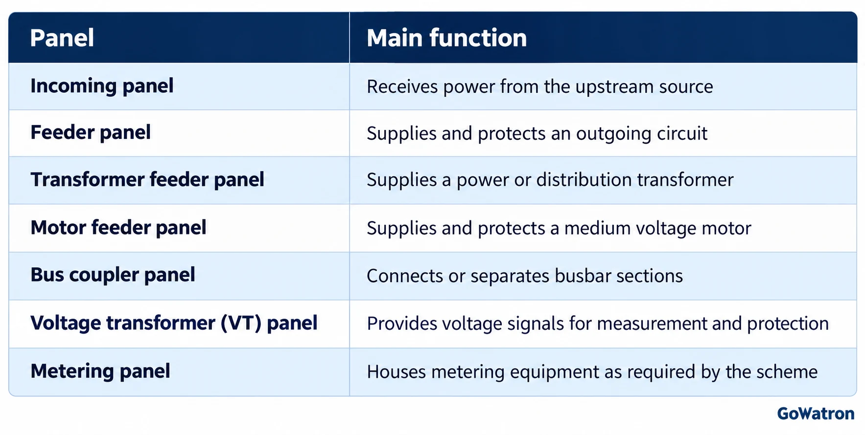
KYN28A-12 is generally considered when the project requires multiple feeder functions, comprehensive protection and a withdrawable circuit-breaker arrangement. The selected assembly’s rated voltage, current, fault level and tested configuration must be verified against the project specification.
4. Fixed-Type Medium Voltage Switchgear
Fixed-type switchgear uses a switching device installed in a fixed position rather than on a withdrawable truck. Depending on the design, it may include a circuit breaker, disconnectors and an earthing switch.
A commonly encountered Chinese model designation is XGN2-12, although construction and configuration must be checked against the individual manufacturer’s documentation.
Fixed-type switchgear may be considered for:
- Industrial distribution systems;
- Replacement of existing fixed switchgear;
- Projects with a defined and stable primary scheme;
- Applications where a withdrawable circuit breaker is not specified.
When comparing fixed and withdrawable switchgear, consider the isolation method, maintenance procedure, accessibility, interlocking and outage requirements. A fixed device should not be assumed to provide the same maintenance arrangement as a withdrawable device.
5. Ring Main Units for 11 kV Distribution
5.1 What Is an 11 kV Ring Main Unit?
An 11 kV ring main unit, or RMU, is a compact assembly of switching units commonly used in medium voltage distribution networks. It can be used in ring, radial or other arrangements, depending on the network design.
An RMU may include:
- Cable switching units;
- Load-break switches;
- Switch-fuse combination units;
- Vacuum circuit-breaker units;
- Earthing switches;
- Voltage indication and monitoring equipment;
- Protection and remote control functions, where specified.
An RMU is often selected for compact distribution substations, commercial facilities, industrial networks and renewable energy auxiliary distribution.
5.2 XGN15-12 and HXGN15-12 Ring Main Units
- XGN15-12 and HXGN15-12 are designations encountered in Chinese ring main switchgear products. The available functional units and insulation arrangements differ between product designs.
- A typical arrangement may include two cable switch units and one transformer feeder unit, but the actual circuit configuration must be chosen from the project’s single-line diagram.
5.3 Load-Break Switch, Switch-Fuse Combination or Circuit Breaker?
This distinction is important when selecting an 11 kV RMU.
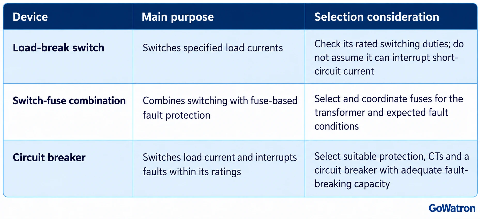
An RMU does not automatically include a circuit breaker or a numerical protection relay. The selected functional unit must match the required protection scheme.
6. Air-Insulated, Gas-Insulated and Solid-Insulated Switchgear
6.1 Air-Insulated Switchgear
Air-insulated switchgear (AIS) uses air as the principal insulating medium between relevant live parts. Many withdrawable metal-clad switchgear designs use air insulation together with vacuum circuit breakers.
Typical advantages include:
- A broad choice of panel configurations;
- Suitability for primary distribution;
- No insulating-gas handling for the air-insulated parts;
- Access arrangements determined by the switchgear design.
Its footprint and clearances depend on the rated voltage, construction and safety requirements.
6.2 Gas-Insulated Switchgear
Gas-insulated switchgear (GIS) encloses relevant primary components in an insulating gas system. It is often selected where a compact installation is required.
Depending on the product, the insulation medium may be SF₆ or an alternative gas. The choice should be based on the project specification, local regulations, environmental requirements and the manufacturer’s service documentation.
Before selecting GIS, check:
- The specified insulating medium;
- Gas monitoring and alarm provisions, where applicable;
- Expansion and replacement arrangements;
- Installation and maintenance requirements;
- End-of-life gas handling requirements.
6.3 Solid-Insulated Switchgear
Solid-insulated switchgear uses solid insulating materials around specified primary components. Its detailed construction varies by manufacturer.
When comparing solid-insulated equipment with other technologies, review the complete product design, including accessible connections, switching devices, environmental limits, type tests and maintenance requirements.
7. Can 12 kV Switchgear Be Used in an 11 kV System?
Yes. A suitably rated 12 kV switchgear assembly can be selected for an 11 kV nominal system, provided its rated voltage and all other ratings meet the system and project requirements.
The terms refer to different quantities:
11 kV; Nominal voltage used to describe the electrical system
12 kV; Rated voltage of the switchgear assembly
For example, KYN28A-12 is marketed for 10 kV networks with a switchgear rated voltage of 12 kV. A 12 kV rating is also available in internationally supplied medium voltage switchgear.
However, the 12 kV label alone is not enough. The project engineer should verify:
- The system’s specified highest voltage;
- The rated voltage of the complete switchgear and its components;
- Power-frequency and lightning impulse withstand levels;
- Rated frequency;
- Short-circuit making, breaking and withstand duties;
- Site conditions and any required derating;
- The applicable standards and utility specification.
The final selection should be based on the project’s electrical studies and approved equipment documentation.
8. Key Technical Parameters for 11 kV Switchgear Selection
8.1 Rated Voltage and Insulation Level
Select a rated voltage that is suitable for the system’s highest voltage and complies with the applicable standard. Also specify the required:
- Rated power-frequency withstand voltage;
- Rated lightning impulse withstand voltage;
- Insulation performance under the specified site conditions.
The required values should come from the applicable standard and project specification; they should not be selected solely from the nominal 11 kV system voltage.
8.2 Rated Frequency
- Confirm whether the network operates at 50 Hz or 60 Hz. Chinese domestic designs commonly use 50 Hz, but an export project may specify 60 Hz. The complete assembly and its components must be suitable for the specified frequency.
8.3 Rated Current
The switchgear’s busbar and feeder current ratings must accommodate the expected continuous operating current, including the effects of ambient temperature, ventilation, grouping and any applicable derating.
For a balanced three-phase load, an approximate current can be calculated as:
\[ I=\frac{S}{\sqrt{3}\,U} \]
Where:
– \(I\) = line current in A;
– \(S\) = three-phase apparent power in VA;
– \(U\) = line-to-line voltage in V.
Example: For a 10 MVA transformer at 11 kV:
\[ I=\frac{10{,}000{,}000}{\sqrt{3}\times11{,}000}\approx525\ \text{A} \]
A 630 A feeder may be a starting point for evaluation, but its suitability must be confirmed against overload requirements, site conditions, derating and the complete equipment rating.
8.4 Short-Circuit Ratings
The switchgear must withstand or interrupt the prospective fault duty at its installation point.
Check the following separately:
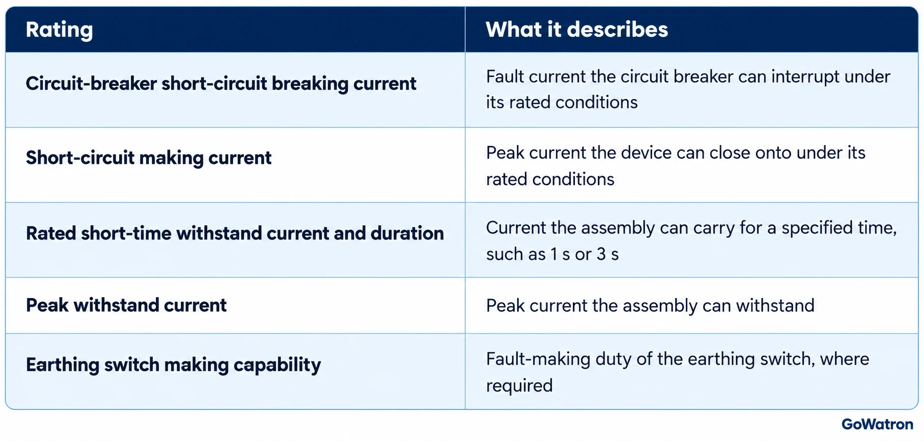
These ratings are not interchangeable. They must be checked against the maximum prospective fault current, peak duty, protection clearing time and the approved short-circuit study.
8.5 Internal Arc Classification
- Where required, specify the internal arc classification (IAC), including accessible sides, test current and duration.
- An IAC designation may identify access from the front, lateral and rear sides. It also states the test current and duration. Verify that the classification applies to the actual panel configuration, installation arrangement and pressure-relief design.
- An IAC rating does not replace safe operating procedures, correct installation, protection coordination or arc-flash risk assessment.
8.6 Service Continuity and Partition Class
- For metal-enclosed switchgear, the project may specify a loss of service continuity category, such as LSC2A or LSC2B, and a partition class.
- These classifications describe aspects of access and separation; they should be verified in the manufacturer’s documents rather than inferred from the model name.
8.7 Site and Environmental Conditions
Check:
- Maximum and minimum ambient temperature;
- Altitude;
- Relative humidity and condensation;
- Dust, corrosion and pollution;
- Indoor or outdoor installation;
- Seismic requirements, where applicable;
- Cable access and maintenance clearances;
- Required enclosure protection.
At high altitude or under non-standard ambient conditions, insulation and current-carrying performance may require special consideration or derating.
9. Protection Functions for 11 kV Switchgear
Protection functions should be selected according to the equipment being protected, the system earthing method and the protection coordination study. The following table lists commonly considered functions and reference relay models for different switchgear applications.
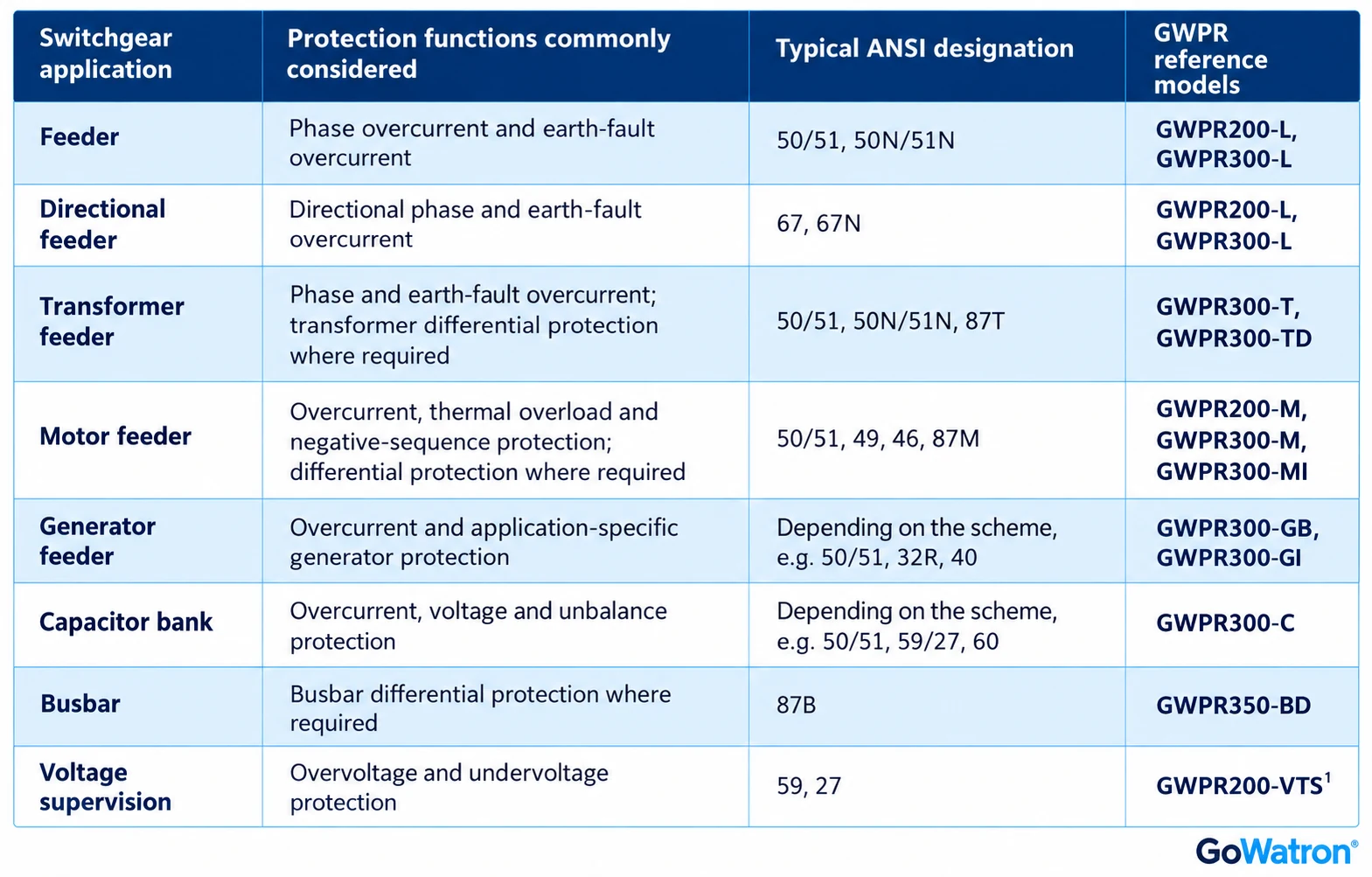
- The GWPR200-VTS is a busbar voltage-transformer supervision relay. Its available protection and supervision functions, including the applicable 59/27 functions, should be confirmed against the selected configuration and product specification.
- Note: The listed GWPR models are references for the corresponding applications. Functions shown in each row are not necessarily available in every listed model. For example, motor differential protection (87M) requires a suitable differential relay and CT arrangement. The GWPR300-MI may be considered where motor differential protection is specified. Confirm the protection functions, current and voltage inputs, communication options and configuration against the applicable product specifications.
- The table is a guide to commonly considered functions; it is not a complete protection design. CT and VT ratios, relay inputs, circuit-breaker tripping circuits, protection settings and coordination must be engineered for the actual installation.
- For earth-fault protection, the appropriate method depends on the system earthing arrangement. Directional earth-fault protection also requires suitable current and voltage inputs and an appropriate directional polarising method.
10. Control, Measurement and Communication
Modern 11 kV switchgear can be equipped with numerical protection relays, meters, bay control units and remote monitoring interfaces.
Depending on the project and device configuration, functions may include:
- Circuit-breaker and earthing-switch position indication;
- Local and remote circuit-breaker control;
- Current, voltage, power and energy measurement;
- Alarm and event recording;
- Fault recording;
- Interlocking and control logic;
- Time synchronisation;
- Communication with a substation automation system or a supervisory control and data acquisition (SCADA) system.
Communication protocols may include IEC 61850, IEC 60870-5-104 or Modbus, subject to the selected equipment and project specification. The required protocol, physical interface, network architecture and interoperability tests should be specified at the ordering stage.
11. How to Select the Right 11 kV Switchgear
A practical selection process can follow these steps:
- Define the system: Confirm nominal and highest system voltage, frequency, earthing method and operating arrangement.
- Prepare the single-line diagram: Identify incoming, outgoing, bus coupler, transformer, motor, metering and VT panels.
- Complete the electrical studies: Determine load currents, prospective short-circuit currents and protection clearing times.
- Choose the switchgear arrangement: Compare metal-clad, fixed-type, RMU and other solutions against the application and maintenance needs.
- Choose the insulation and switching technology: Evaluate air, gas or solid insulation and the required circuit breaker, load-break switch or switch-fuse unit.
- Specify protection and control: Define relay functions, CTs, VTs, interlocking, trip circuits, communication and SCADA interfaces.
- Verify installation and safety requirements: Confirm internal arc requirements, access, pressure relief, clearances and environmental conditions.
- Review the tested design: Check ratings, type-test evidence, drawings and documentation for the actual configuration offered.
Selection Examples
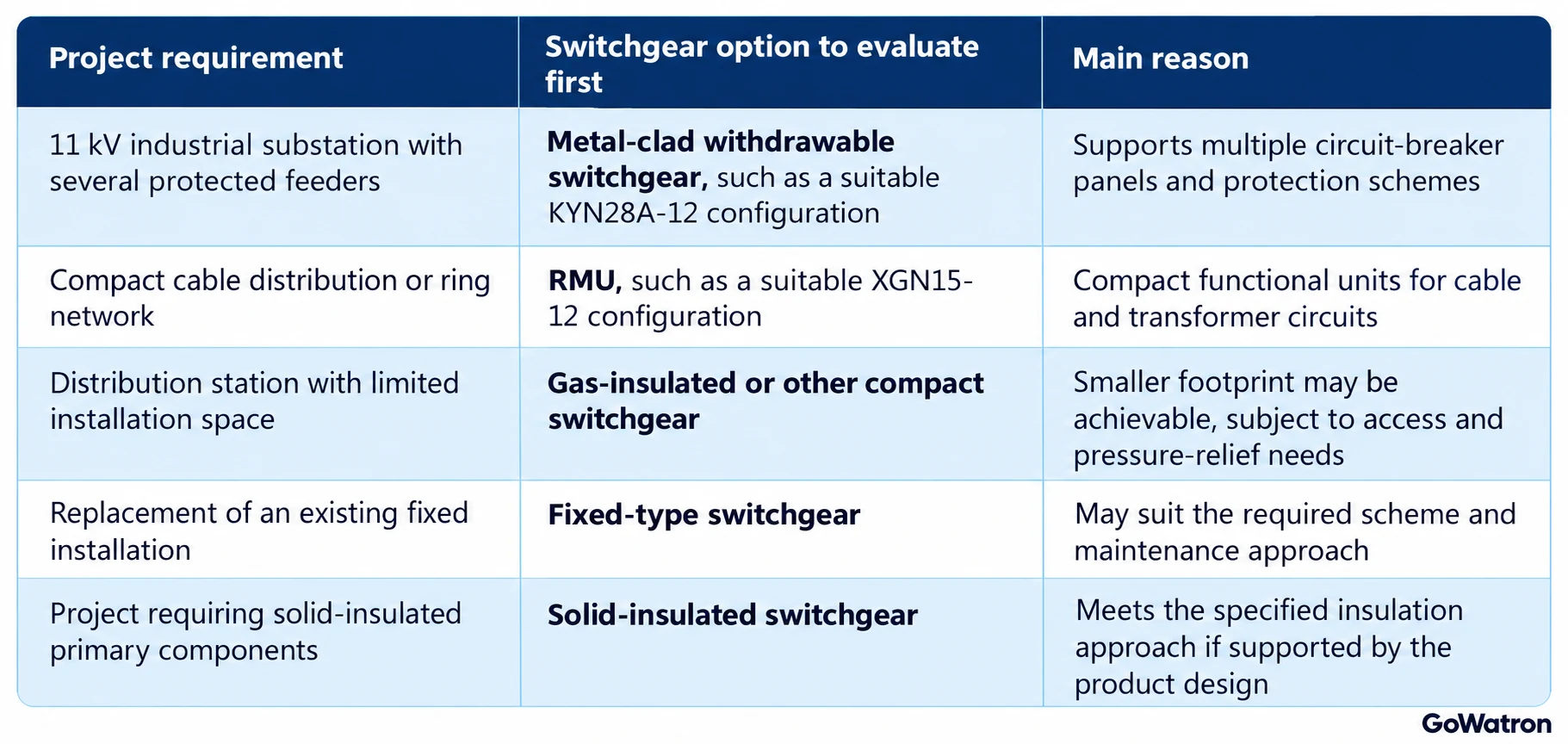
The final decision depends on the project’s electrical, safety, maintenance and commercial requirements.


