Switchgear Protection Relays Selection Guide: Types, ANSI Protection Functions, Technical Specifications and Applications
- Switchgear protection relays are essential secondary protection devices in medium-voltage power distribution systems. They detect electrical faults and abnormal operating conditions, including short circuits, earth faults, overloads, voltage abnormalities and equipment-related faults. When predefined protection criteria are satisfied, the relays initiate alarms or issue trip commands to circuit breakers to isolate the affected circuits.
- In substations, industrial power distribution networks, power plants, renewable energy installations and large infrastructure facilities, different types of switchgear require different protection functions, technical specifications, communication interfaces and control logic.
- Selecting a switchgear protection relay requires more than considering the system voltage. The selection process must also account for the switchgear application, protected equipment, system earthing arrangement, current transformer (CT) and voltage transformer (VT) configurations, prospective short-circuit currents, protection coordination and SCADA communication requirements.
- This guide explains the classification, ANSI protection functions, key technical parameters and selection methods for protection relays used in 6.6 kV, 11 kV, 22 kV and 33 kV medium-voltage switchgear. Typical applications and configurations are illustrated using the GoWatron GWPR200 series.
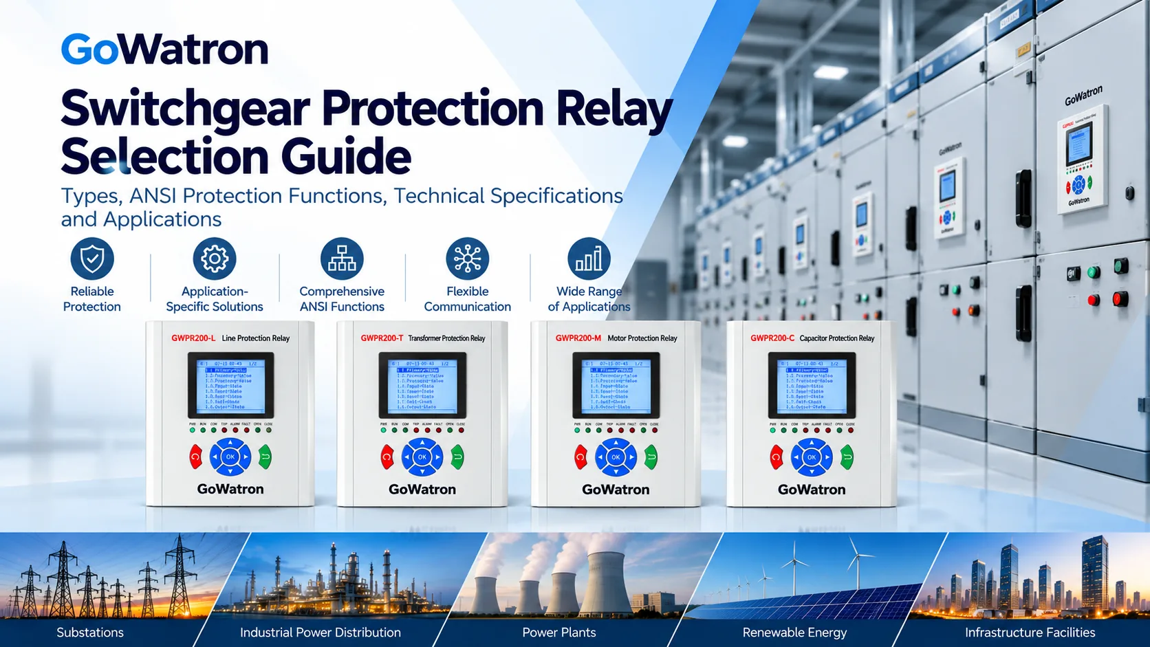
1. What Is a Switchgear Protection Relay?
- A switchgear protection relay is a numerical protection device designed to monitor electrical system conditions, detect faults and initiate circuit-breaker operation when specified protection criteria are met.
- Protection relays are typically installed in the low-voltage compartment of medium-voltage switchgear assemblies. They receive electrical measurements and equipment status signals through current transformers (CTs), voltage transformers (VTs) and digital inputs.
- When a measured quantity exceeds a configured threshold or other protection operating conditions are satisfied, the relay initiates an alarm or trip command according to its protection settings and operating logic.
- In this guide, the term switchgear protection relay refers to a numerical protection relay installed in or associated with a medium-voltage switchgear assembly.
- The term switchgear is used in its conventional industry context, while medium-voltage switchgear assembly is used where greater technical precision is required.
1.1 Main Functions of Switchgear Protection Relays
- Fault protection: Detects phase overcurrent, earth faults, overloads, negative-sequence currents and abnormal voltage conditions.
- Electrical measurement: Monitors current, voltage, frequency, power and other operating parameters.
- Circuit-breaker control: Supports opening and closing commands, circuit-breaker position monitoring and electrical interlocking.
- Event recording: Records protection operations, alarms, circuit-breaker status changes and fault information.
- Remote communication: Enables integration with automation systems through protocols such as Modbus, IEC 60870-5-103, IEC 60870-5-104 and optional IEC 61850, depending on the relay model and configuration.
1.2 Main Types of Switchgear Protection Relays
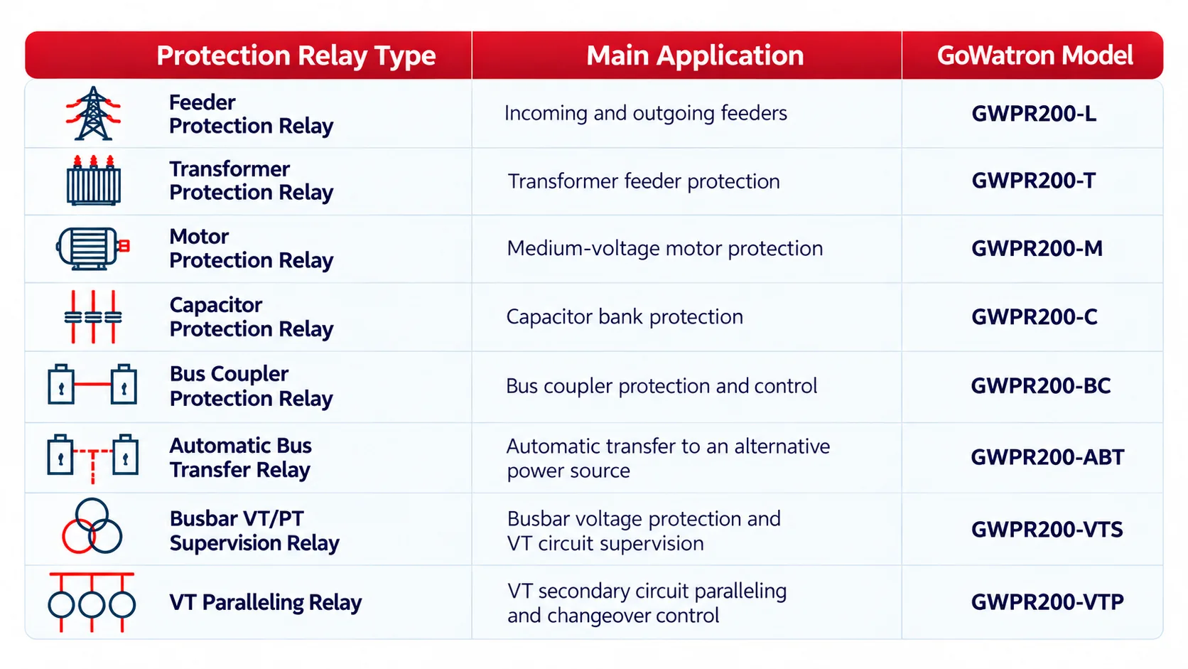
For applications requiring differential protection, high-speed bus transfer or dedicated arc-flash protection, suitable devices from the GWPR300, GWPR320 or GWPR350 series may be considered according to project requirements.
2. How to Select Protection Relays for Different Types of Switchgear
- The application of the switchgear determines its primary protection requirements. Even at the same voltage level, incoming feeders, outgoing feeders, transformer feeders, motor feeders and bus couplers may require significantly different protection functions.
2.1 Incoming and Outgoing Feeder Protection
- Recommended Model: GWPR200-L Feeder Protection Relay
- Incoming and outgoing feeder panels are among the most common types of medium-voltage switchgear. They are used for power supply connections, electricity distribution and feeder fault isolation.
- The GWPR200-L is designed for the protection, measurement and control of medium-voltage incoming feeders, outgoing feeders and cable circuits.
Typical protection functions include:
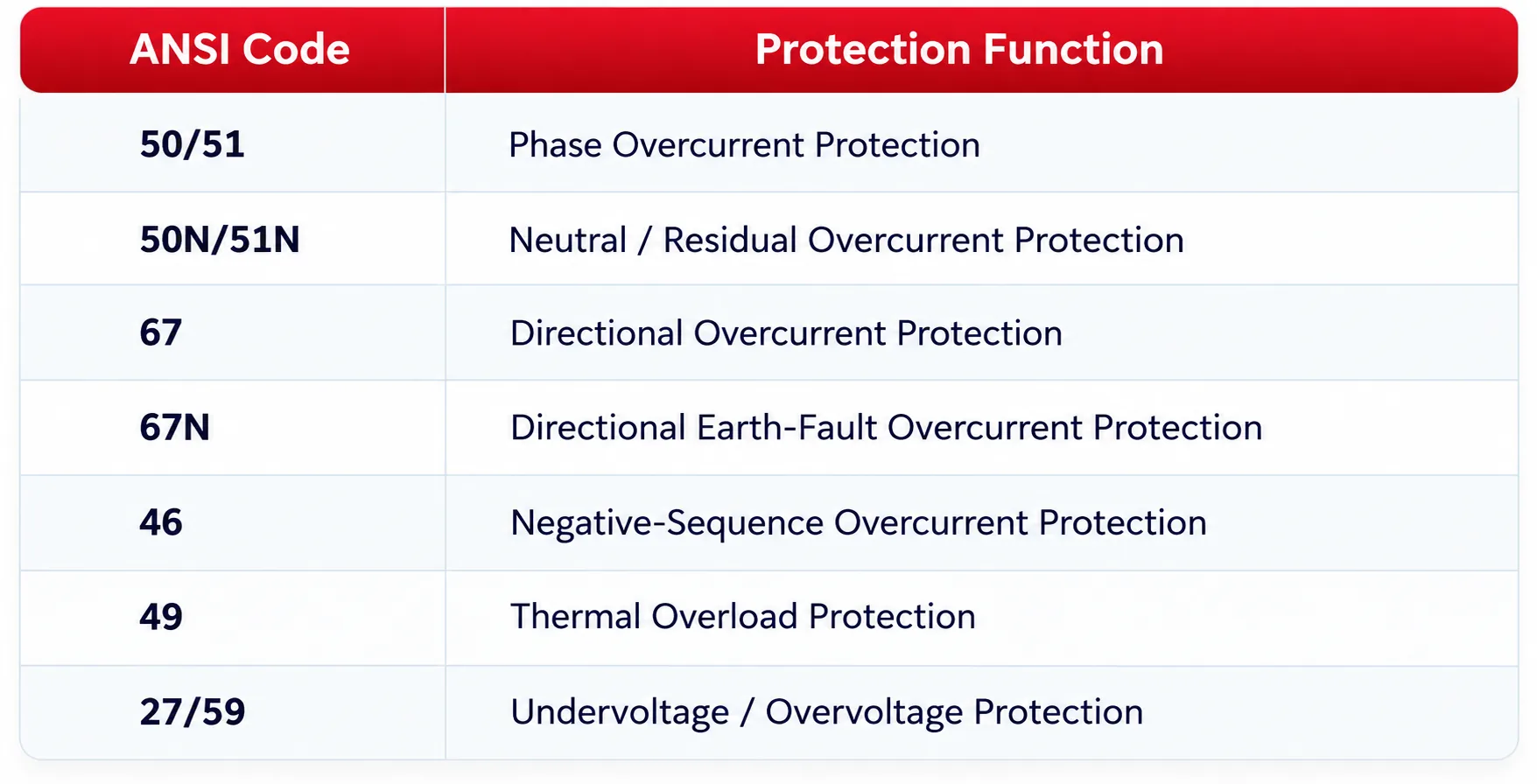
- For radial feeders supplied from a single source, phase overcurrent and earth-fault protection generally form the basis of the protection scheme.
- For ring networks, dual-source systems or feeders where fault current may flow in either direction, directional overcurrent and directional earth-fault protection should be considered according to the short-circuit study and protection coordination requirements.
- Directional Overcurrent Protection (ANSI 67) uses both current magnitude and directional criteria to determine whether a fault is within the configured operating direction. Depending on the protection settings and system requirements, the relay may be configured to operate for forward or reverse faults.
- ANSI 67 denotes directional overcurrent protection and should not be interpreted exclusively as reverse overcurrent protection.
2.2 Transformer Feeder Protection
- Recommended Model: GWPR200-T Transformer Protection Relay
- Transformer feeder switchgear is used to supply distribution transformers and provide electrical fault protection and operating condition supervision.
- The GWPR200-T is suitable for transformer feeder electrical protection and the supervision of external transformer protection signals.
Typical protection functions include:
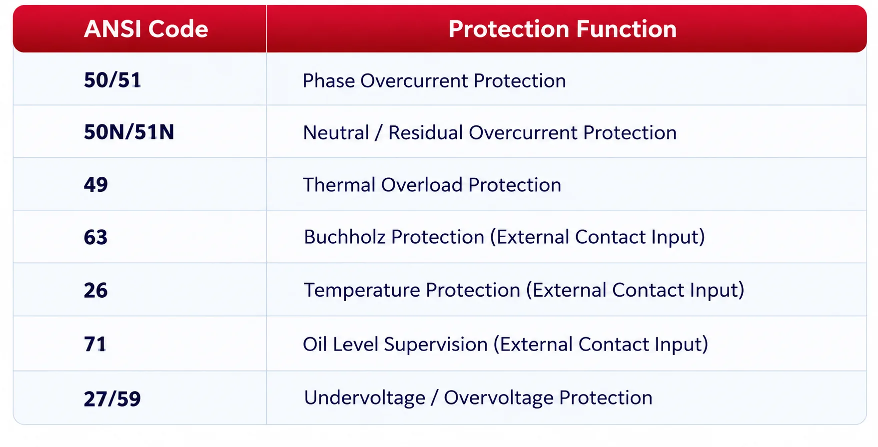
- ANSI 63 identifies a pressure- or gas-actuated device, such as a transformer Buchholz relay. In this application, the GWPR200-T receives alarm or trip contact signals from an external transformer-mounted Buchholz relay through its digital inputs.
- Similarly, transformer temperature and oil level supervision may be implemented using external device contacts associated with ANSI 26 and ANSI 71.
- These functions do not imply that the GWPR200-T directly measures transformer gas accumulation, oil temperature or oil level. The actual monitoring and protection arrangement depends on the external devices, wiring configuration and programmed relay logic.
- For larger or critical transformers requiring transformer differential protection (ANSI 87T), the GWPR300-TD Transformer Differential Protection Relay may be considered.
- Transformer differential protection requires appropriate CT locations, ratio compensation, transformer vector group compensation and magnetising inrush restraint or blocking.
- Conventional overcurrent protection cannot be regarded as a direct replacement for transformer differential protection.
2.3 Motor Switchgear Protection
- Recommended Model: GWPR200-M Motor Protection Relay
- Medium-voltage motor switchgear is widely used for industrial pumps, fans, compressors, conveyors and other motor-driven equipment.
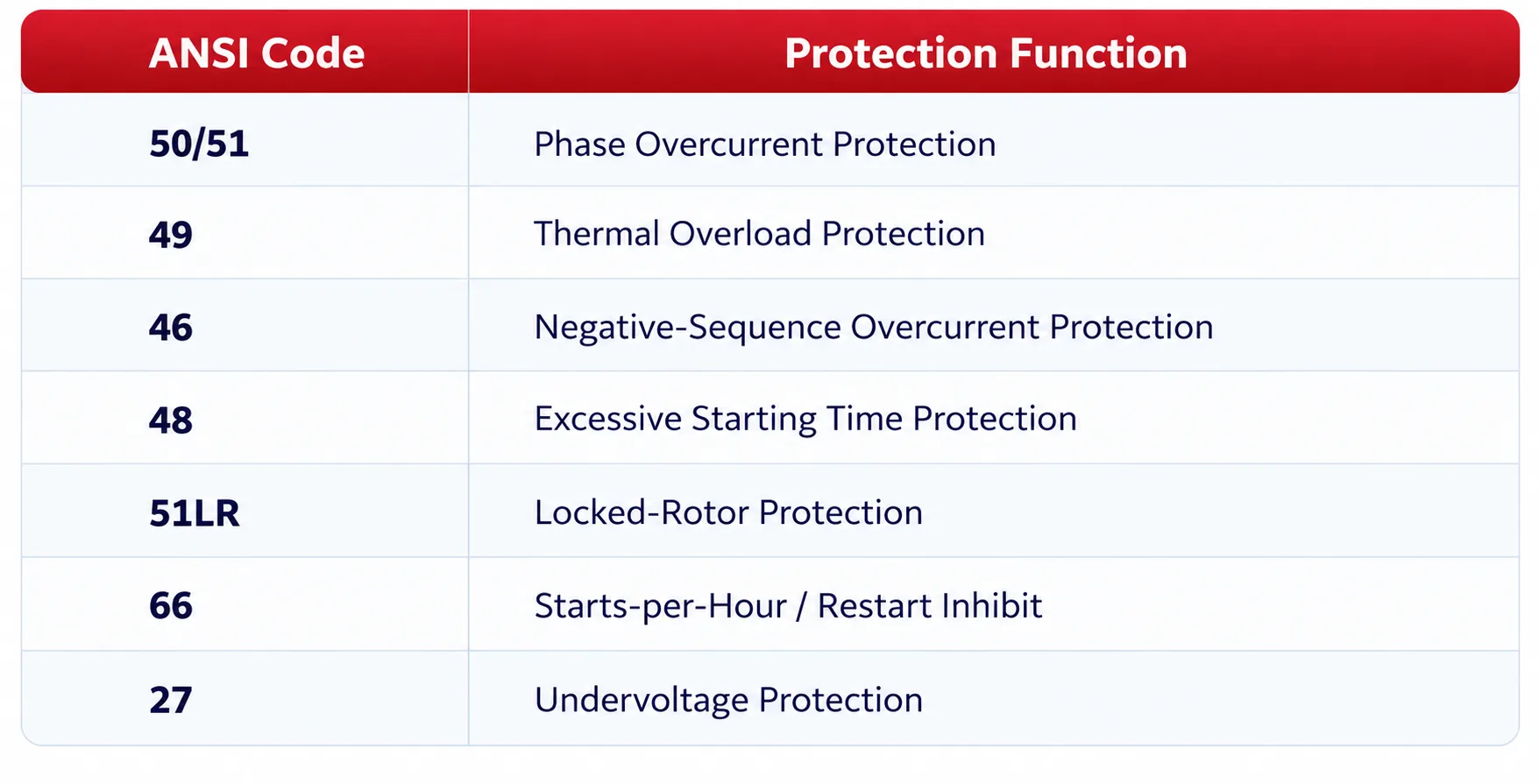
- Unlike general feeder protection, motor protection must account for starting characteristics, thermal capacity, locked-rotor conditions and phase-current unbalance.
Typical protection functions include:
2.4 Capacitor Bank Switchgear Protection
- Recommended Model: GWPR200-C Capacitor Protection Relay
- Capacitor bank switchgear is used for reactive power compensation, power factor correction and voltage support.
- Capacitor banks may experience switching inrush currents, harmonic distortion, overvoltage conditions and internal capacitor element failures.
- Consequently, capacitor bank protection requires more than conventional overcurrent protection. Depending on the capacitor bank configuration, appropriate unbalance protection may also be necessary.
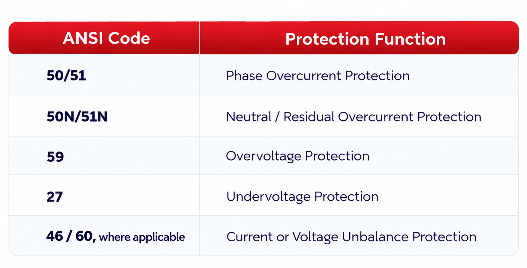
- For double-star capacitor banks, the appropriate current or voltage unbalance protection scheme should be selected according to the neutral connection arrangement and measurement configuration.
- Key selection considerations: Capacitor bank rated voltage, reactive power rating, connection arrangement, switching inrush current, harmonic conditions and unbalance protection sensitivity.
- The exact ANSI designation for capacitor unbalance protection should be verified against the implemented protection function and the applicable project specification. ANSI 46 and ANSI 60 are not universally interchangeable designations for all capacitor bank unbalance schemes.
2.6 Automatic Bus Transfer Protection and Control
- Recommended Model: GWPR200-ABT Automatic Bus Transfer Relay
- An automatic bus transfer relay is used in dual-source power distribution systems to transfer the load to an alternative power source when the normal source becomes unavailable and the predefined transfer conditions are satisfied.
- The GWPR200-ABT is intended for automatic transfer applications involving dual incoming feeders, sectionalised busbars and other supported power supply arrangements.
Typical functions include:
- Normal and alternative source voltage monitoring
- Busbar undervoltage detection
- Incoming and bus coupler circuit-breaker status monitoring
- Automatic transfer control logic
- Circuit-breaker opening and closing commands
- Transfer blocking, interlocking and abnormal condition alarms
The selection of an automatic bus transfer relay should focus on the transfer sequence, voltage supervision, circuit-breaker operating conditions, interlocking requirements and prevention of unauthorised source paralleling.
- For critical industrial loads requiring a shorter supply interruption, a dedicated high-speed bus transfer (HSBT) system may be considered.
- Automatic bus transfer (ABT) and high-speed bus transfer (HSBT) are distinct applications.
- Conventional ABT schemes generally initiate source transfer after predefined voltage, source availability and circuit-breaker conditions have been satisfied.
- HSBT schemes are designed to minimise supply interruption and may use fast-transfer, in-phase transfer or residual-voltage transfer strategies, depending on the system design and operating conditions.
- Actual transfer times depend on the transfer method, circuit-breaker operating characteristics, voltage and phase-angle conditions, and system configuration. They should be verified against the equipment specifications rather than assumed to be a fixed value.
2.7 Busbar VT Supervision and VT Paralleling
- Recommended Models: GWPR200-VTS / GWPR200-VTP
- In this section, VT (Voltage Transformer) is used consistently in accordance with IEC terminology. PT (Potential Transformer) is an alternative term commonly used in some markets and technical documentation. Both terms refer to the same general category of instrument transformer.
- The GWPR200-VTS retains VT/PT in its product name, while the GWPR200-VTP uses VT in its product name. Both devices are associated with voltage transformer secondary circuits but perform different functions: voltage supervision and VT paralleling, respectively.
- Busbar voltage transformer circuits provide voltage signals for protection, measurement, control and substation automation systems.
- Depending on the busbar arrangement and operating requirements, separate devices may be used for voltage supervision and VT secondary circuit paralleling.
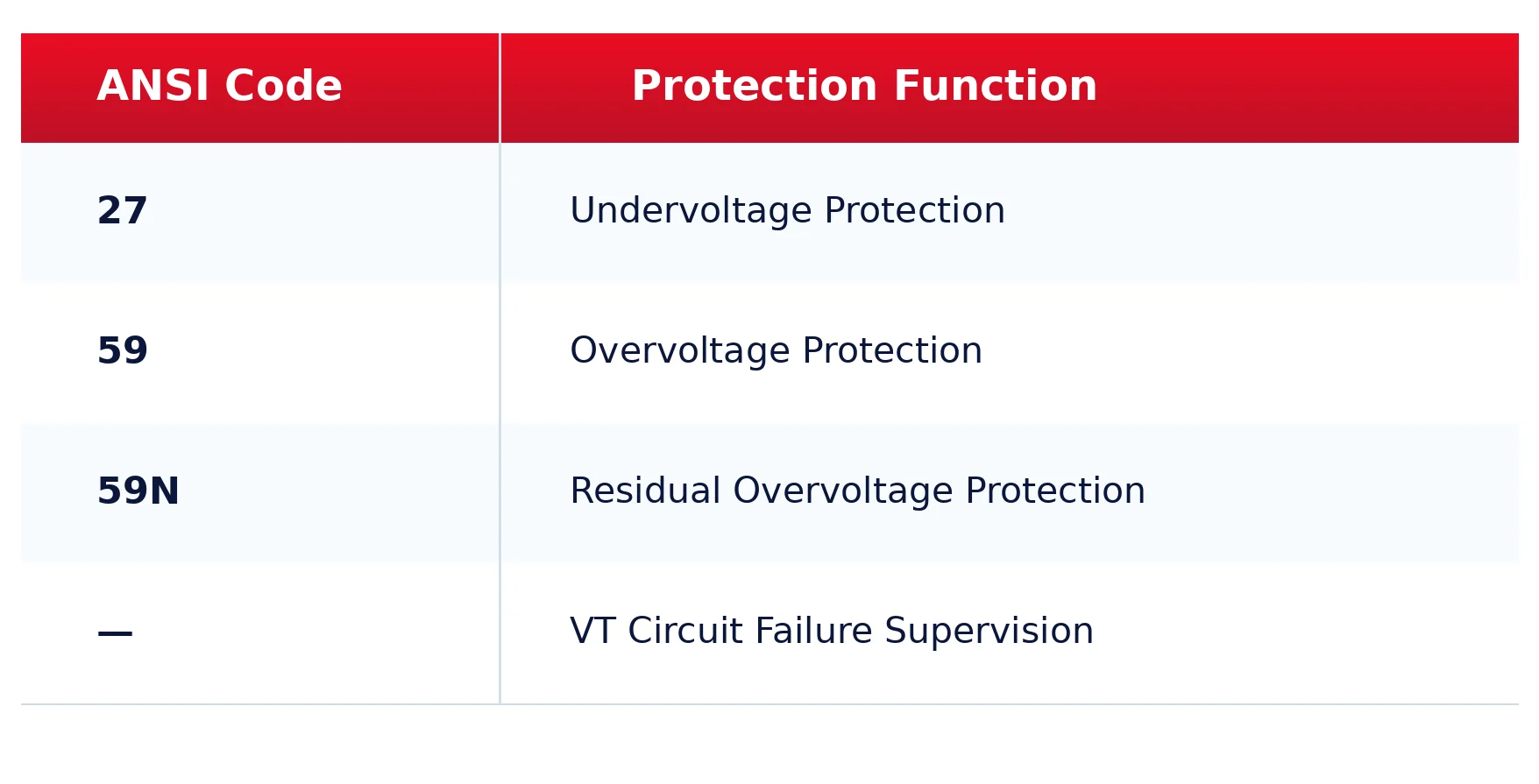
- GWPR200-VTS Busbar VT/PT Supervision Relay
- The GWPR200-VTS is intended for busbar voltage monitoring, voltage protection and VT circuit supervision in medium-voltage switchgear applications.
- Additional frequency-related functions, where required, should be confirmed against the product specifications.
- The GWPR200-VTS can provide voltage supervision and alarm or protection signals for associated switchgear and automation equipment, subject to its configured functions.
GWPR200-VTP VT Paralleling Relay
The GWPR200-VTP is intended for VT secondary circuit paralleling and changeover control in sectionalised busbar systems.
Typical functions include:
- Busbar VT secondary circuit status monitoring
- VT secondary voltage selection and changeover control
- VT paralleling control according to the configured operating logic
- Bus coupler and disconnector position supervision
- Electrical interlocking and paralleling permissive checks
- Abnormal condition alarms and operation blocking
- The VT paralleling scheme must prevent unintended connections between incompatible secondary voltage sources.
Paralleling permissive conditions should be coordinated with the primary busbar arrangement, circuit-breaker and disconnector positions, VT secondary circuit design and the applicable electrical interlocking requirements.
Application Note: The GWPR200-VTS performs voltage protection and VT circuit supervision, whereas the GWPR200-VTP performs VT secondary circuit paralleling and changeover control. These devices serve different functions and should not be treated as interchangeable.
3. Common ANSI Protection Functions for Switchgear
ANSI device function numbers provide a standardised reference for identifying protection and control functions in electrical power systems.
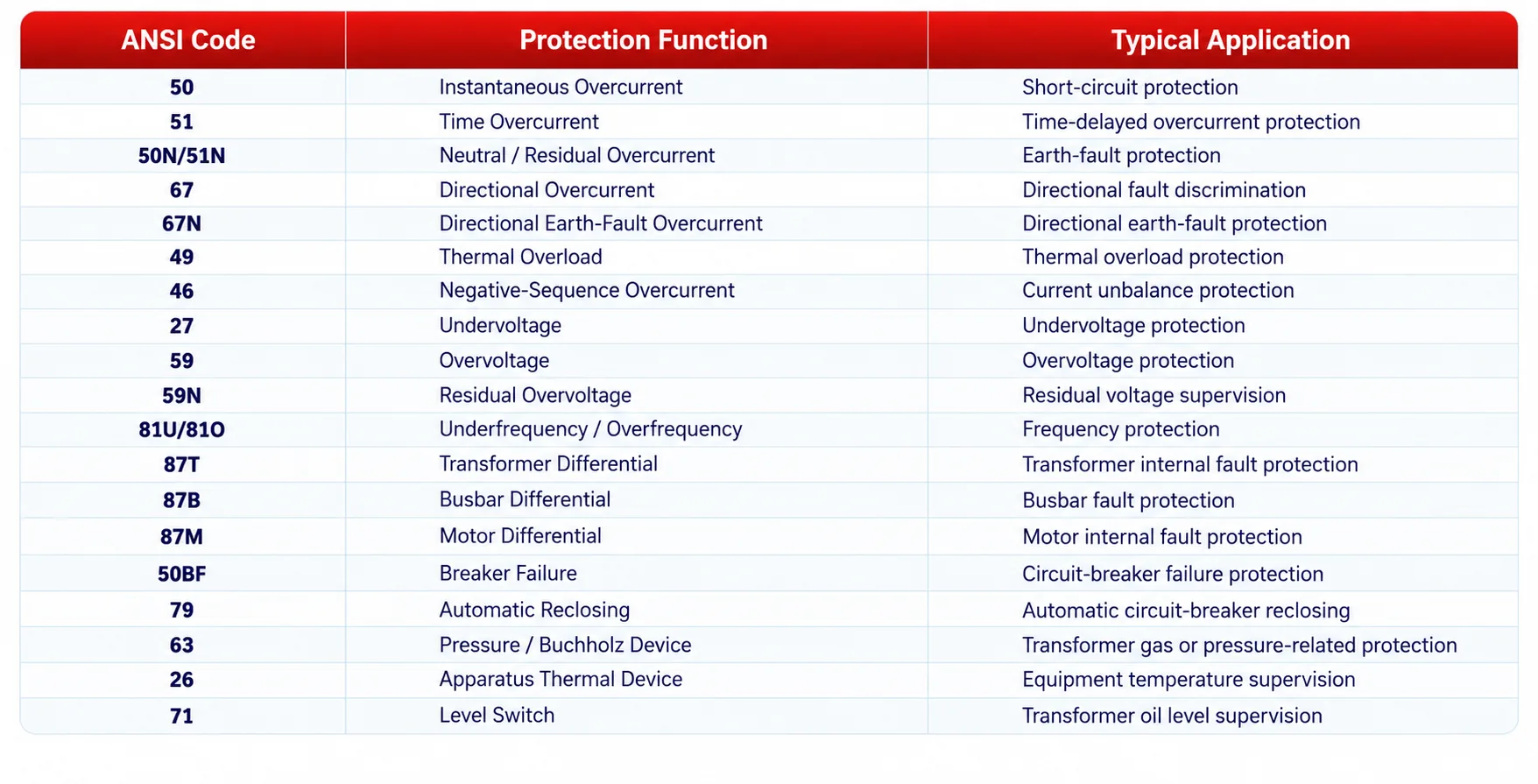
- The ANSI codes identify protection or device functions but do not define the number of protection stages, setting ranges or specific operating logic available in a particular relay.
- These characteristics must be verified against the relevant product technical specifications.
- ANSI 63 Application Note: ANSI 63 identifies a pressure- or gas-actuated device, including a transformer Buchholz relay. As described in Section 2.2, Buchholz protection in the GWPR200-T application is implemented through external contact inputs from the transformer-mounted device. The protection relay receives the corresponding alarm or trip signals rather than directly measuring gas accumulation or internal transformer pressure.
- Directional Protection Note: ANSI 67 and ANSI 67N refer to directional overcurrent and directional earth-fault overcurrent protection, respectively. The directional element determines whether the measured fault conditions correspond to the configured operating direction.
- Forward and reverse operation are determined by the relay’s directional reference, polarising quantities and protection settings. Reverse overcurrent protection is therefore a possible application of a directional overcurrent element, rather than a separate standard ANSI function.
4. Key Technical Parameters for Switchgear Protection Relay Selection
4.1 Rated System Voltage
The protection relay must be suitable for the switchgear application and the associated CT/VT secondary circuit configuration.
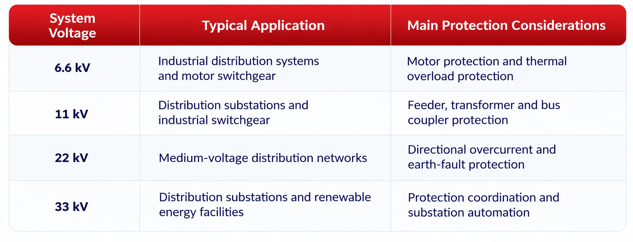
- Protection relays normally receive secondary current and voltage signals from CTs and VTs rather than being connected directly to the primary medium-voltage system.
- Therefore, the rated secondary inputs, insulation requirements and measurement configurations must be verified.
4.2 Current Transformer (CT) Requirements
The CT configuration directly affects measurement accuracy, fault detection sensitivity and protection reliability.
The following parameters should be considered:
- CT transformation ratio
- Rated secondary current: 1 A or 5 A
- Protection accuracy class
- Rated burden and secondary circuit impedance
- CT saturation characteristics under maximum fault conditions
- Protection sensitivity under minimum fault conditions
- Residual current measurement arrangement
For example, consider an 11 kV feeder with a primary load current of 400 A and a CT ratio of 500/1 A.
The CT has a rated primary current of 500 A and a rated secondary current of 1 A. Assuming ideal current transformation, the corresponding secondary current is:
Is = (400 / 500) × 1 = 0.8 A
The protection relay therefore receives a nominal secondary current of 0.8 A under this load condition.
However, the final CT selection must also consider maximum load current, prospective short-circuit currents, CT accuracy class, secondary circuit burden, saturation characteristics and protection sensitivity.
4.3 Voltage Transformer (VT) Requirements
For switchgear requiring voltage protection, directional protection or frequency measurement, the VT configuration must be checked.
Important parameters include:
- VT transformation ratio
- Rated secondary voltage
- VT connection arrangement
- Residual voltage measurement method
- VT circuit failure supervision
- Voltage measurement accuracy
For directional earth-fault protection, the required polarising quantity and the relay’s operating logic under VT circuit failure conditions must also be verified.
4.4 Auxiliary Power Supply and Digital I/O
The relay auxiliary power supply must be compatible with the switchgear control power system.
Common substation control voltages include 110 V DC and 220 V DC, although the actual permitted supply range depends on the relay model.
The following should also be verified:
- Number and rated voltage of digital inputs (DI)
- Number of trip, close and alarm outputs (DO)
- Output contact ratings and DC breaking capacity
- Circuit-breaker position monitoring
- Spring-charged status monitoring, where applicable
- Trip circuit supervision
- Local/remote control and electrical interlocking requirements
4.5 Dimensions and Installation Requirements
Mechanical compatibility is an important consideration, particularly for switchgear refurbishment and relay replacement projects.
The following dimensions and installation requirements should be checked:
- Overall relay dimensions
- Panel cut-out dimensions
- Mounting depth
- Terminal wiring clearance
- Operating temperature and environmental conditions
For retrofit applications, the existing panel cut-out and secondary wiring arrangements should be reviewed before selecting a replacement relay.
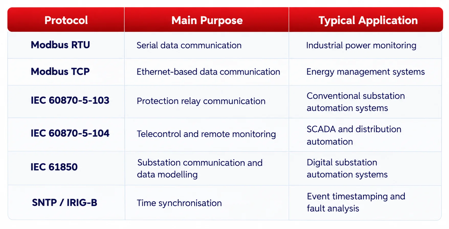
- The GoWatron GWPR200 series provides communication capabilities according to the specific relay model, hardware version and ordered configuration.
- IEC 61850 and other optional protocols should not be assumed to be standard across every GWPR200 model.
- When selecting a relay for SCADA integration, communication port availability, protocol implementation, data point mapping, time synchronisation and system compatibility should be verified.
6. Typical Protection Relay Selection for an 11 kV Switchgear System
- Consider an 11 kV industrial distribution substation with two incoming feeders, two busbar sections, a bus coupler, transformer feeders, motor feeders, a capacitor bank and VT panels.
A typical preliminary relay selection is shown below.
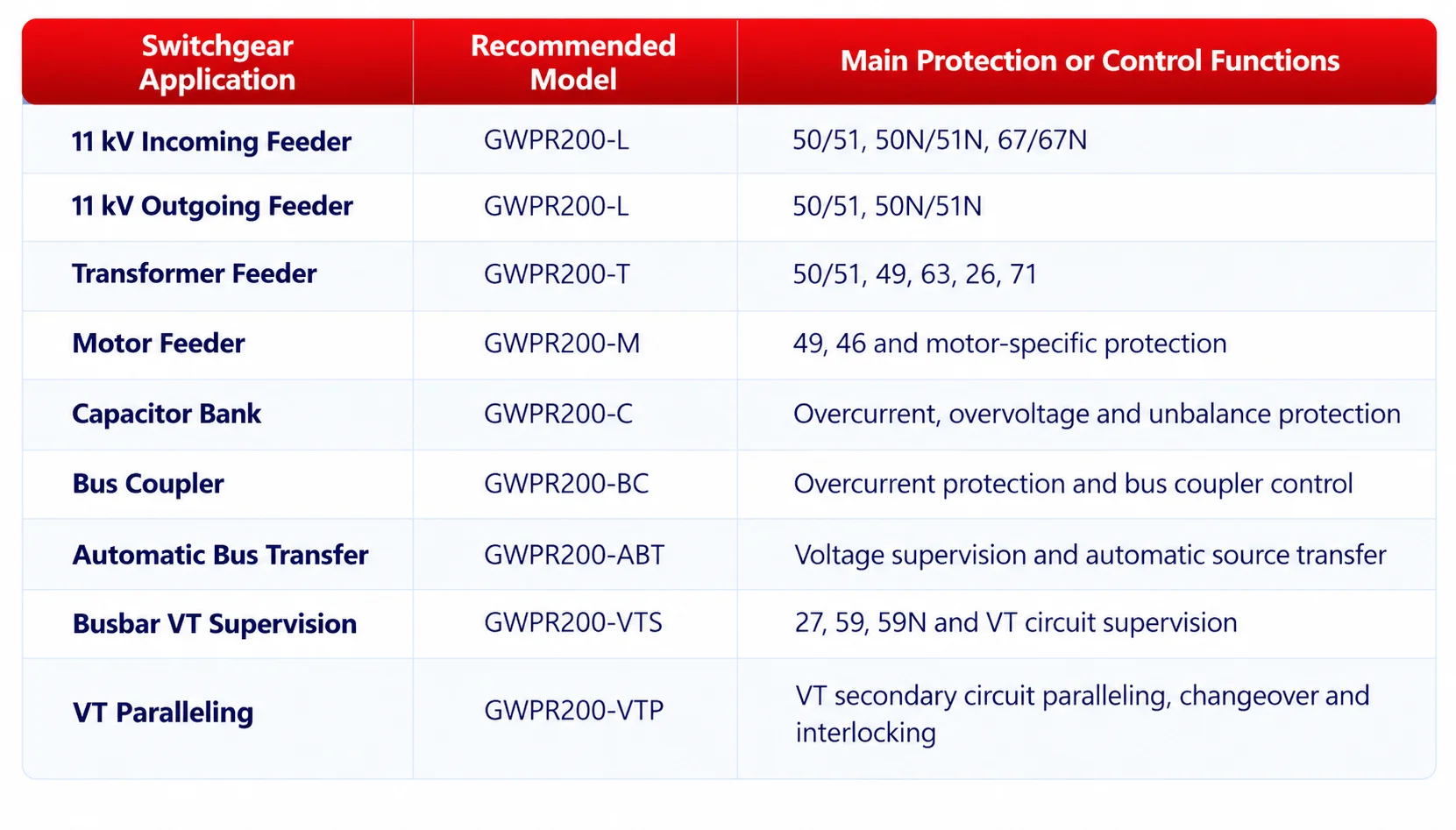
This table provides a preliminary selection reference rather than a complete protection design.
The final configuration must be confirmed using the electrical single-line diagram, protection coordination study, short-circuit calculations, CT/VT specifications, control logic and relay technical documentation.
7. Switchgear Protection Relay Selection Procedure
The following five-step procedure can be used for preliminary relay selection.
Step 1: Identify the Switchgear Application
- Determine whether the relay is required for an incoming feeder, outgoing feeder, transformer, motor, capacitor bank, bus coupler, automatic bus transfer scheme or VT panel.
Step 2: Determine the Required Protection Functions
- Identify the necessary ANSI protection functions, including 50/51, 50N/51N, 67/67N, 49, 27, 59 and any application-specific functions.
Step 3: Verify CT and VT Requirements
- Confirm the CT/VT transformation ratios, accuracy classes, connection arrangements, prospective fault currents and required protection sensitivity.
Step 4: Confirm Control and Communication Requirements
- Check the auxiliary power supply, digital inputs and outputs, circuit-breaker control requirements, SCADA interfaces and communication protocols.
Step 5: Select and Verify the Relay Model
- Select the appropriate GoWatron GWPR200 model and verify its protection functions, technical specifications, installation dimensions and compatibility with the protection coordination scheme.
8. Common Mistakes When Selecting Switchgear Protection Relays
8.1 Selecting a Relay Based Only on System Voltage
- Switchgear operating at the same voltage level may require completely different protection functions.
- For example, an 11 kV feeder relay is not necessarily suitable for an 11 kV motor or capacitor bank application.
8.2 Ignoring the System Earthing Arrangement
- Solidly earthed, resistance-earthed, isolated-neutral and resonant-earthed systems exhibit different earth-fault characteristics.
- The selected protection method must be appropriate for the system earthing arrangement and expected earth-fault current.
8.3 Overlooking CT Saturation and Protection Sensitivity
- A CT ratio suitable for normal load measurement does not automatically guarantee reliable protection operation during faults.
- CT saturation under maximum fault conditions and relay sensitivity under minimum fault conditions must both be evaluated.
8.4 Failing to Verify Communication Compatibility
- Support for the same communication protocol does not necessarily guarantee full system interoperability.
- Communication ports, data mapping, supported services and SCADA compatibility must be checked.
8.5 Neglecting Protection Coordination
- Upstream and downstream protection settings must be coordinated to achieve the required selectivity.
- Incorrect current or time settings may cause unnecessary upstream tripping and increase the extent of supply interruption.
9. Conclusion
- Selecting a switchgear protection relay requires a systematic assessment of the protected equipment, electrical network configuration, ANSI protection functions, CT/VT arrangements, communication requirements and installation conditions.
- For conventional medium-voltage switchgear, the GoWatron GWPR200 series provides application-specific solutions for feeder protection, transformer protection, motor protection, capacitor bank protection, bus coupler control, automatic bus transfer, busbar VT supervision and VT paralleling.
- For more specialised applications requiring transformer differential protection, busbar differential protection, motor differential protection, high-speed bus transfer or dedicated arc-flash protection, suitable devices from the GWPR300, GWPR320 and GWPR350 series may be considered.
- The final relay model and configuration should be determined using the electrical single-line diagram, protection requirements, short-circuit study, coordination calculations and applicable technical specifications.
- Appropriate relay selection contributes to reliable fault detection, selective fault isolation, improved operational safety and efficient power system maintenance.


