XGN15‑12 12 kV Air-Insulated Ring Main Unit (RMU)
Product Desc
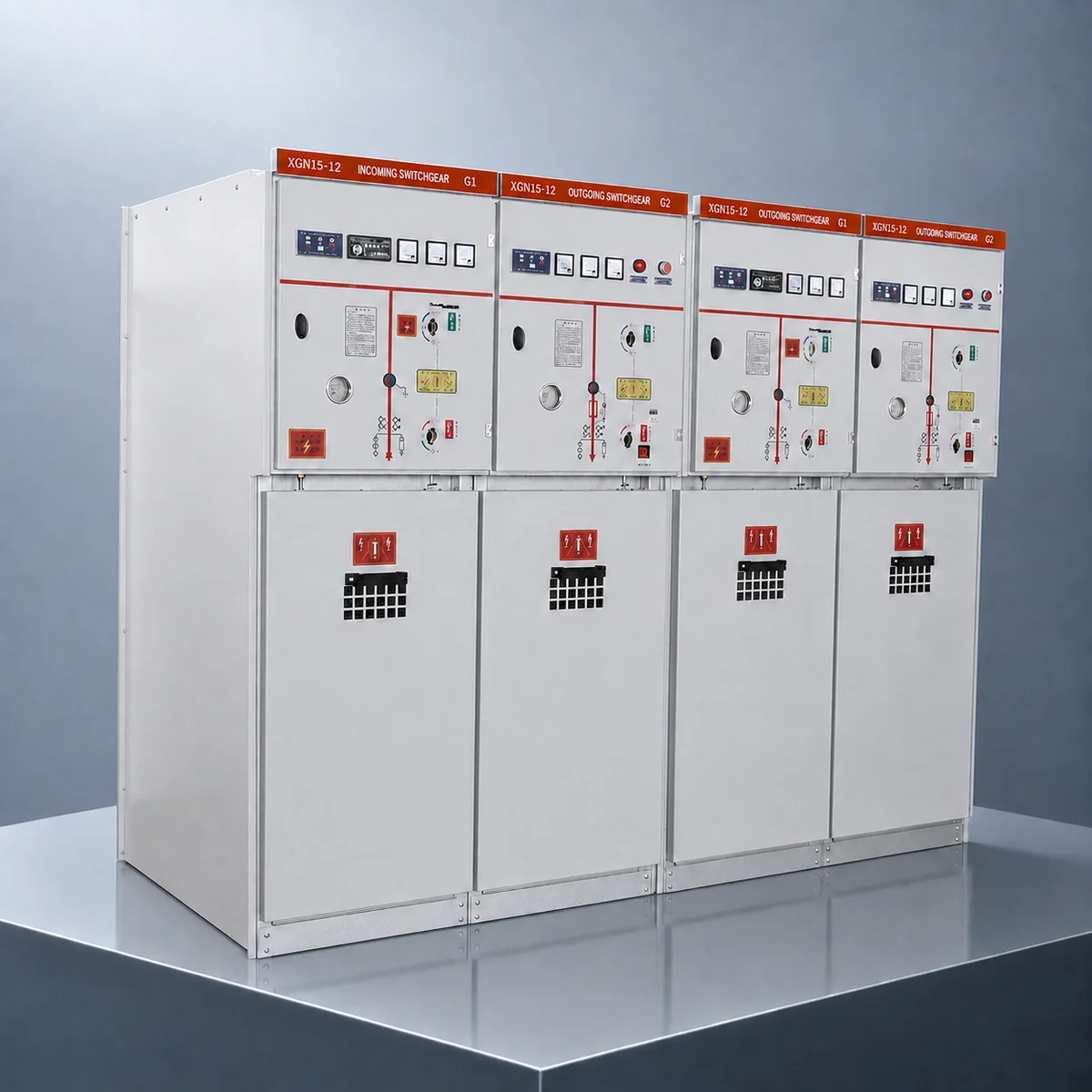
- The XGN15‑12 12 kV Air-Insulated Ring Main Unit (RMU) is indoor fixed-type AC metal-enclosed switchgear designed for 50 Hz, 11 kV/12 kV ring-main and terminal distribution systems.
- Atmospheric-pressure air is used as the principal insulation medium. The RMU can be configured with a vacuum or SF₆ load-break switch, switch-fuse combination or vacuum circuit-breaker. A completely SF₆-free version is also available.
- Its compact, modular and expandable design provides flexible configuration, reliable interlocking and convenient installation. It is suitable for municipal networks, industrial facilities, commercial buildings, prefabricated substations and infrastructure projects.
- The product is designed in accordance with IEC 62271‑1, IEC 62271‑200, IEC 62271‑102, IEC 62271‑103, IEC 62271‑105 and IEC 60529. Final ratings and configurations are subject to project requirements and applicable type-test reports.




12 kV Rated Voltage
11/12 kV Systems

Air Insulated
Atmospheric Air

630 A Rated Current
Standard Configuration

Flexible Switching
LBS · Fuse · VCB

Safety Interlocking
Reliable Operation

IEC Compliant
IEC 62271 Series

Warranty
2 Year Warranty
Product Construction
- The XGN15‑12 adopts a fixed, modular and expandable unit-type construction. It can operate as an individual terminal distribution panel or be assembled with multiple functional units to form a ring-main or radial distribution system.
- The functional units can be arranged according to the single-line diagram to satisfy requirements for incoming feeders, outgoing feeders, transformer protection, bus-section coupling, metering and voltage measurement.
- The enclosure is typically manufactured from high-quality aluminium-zinc-coated steel sheet using CNC machining, bending and riveted assembly processes. This construction provides high mechanical strength and corrosion resistance, reduces welding-related deformation, maintains structural flatness and facilitates manufacturing, transport, installation and maintenance.
Depending on the panel type and primary circuit arrangement, the enclosure may include the following compartments:
- Busbar compartment
- Switching-device compartment
- Operating-mechanism compartment
- Cable compartment
- Low-voltage control or instrument compartment
- The functional sections are separated by appropriate partitions or protective barriers, helping to limit the propagation of an internal fault into adjacent sections. The compartment construction, partition class, loss-of-service-continuity category and internal arc classification shall be confirmed according to the specific design and type-test results of the relevant panel.
- Mechanical or electrical interlocking is provided among the switching devices, disconnector, earthing switch and compartment doors. The operating sequence complies with the applicable requirements of the IEC 62271 series and relevant safety procedures.
Depending on the configuration, the interlocking functions include:
- Preventing inadvertent opening or closing of the circuit-breaker, where fitted, and preventing unauthorised operation of the load-break switch;
- Preventing operation of the disconnector under load;
- Preventing the earthing switch from being closed while the circuit is energised;
- Preventing energisation of the circuit while the earthing switch is closed;
- Preventing access to an energised compartment.
- The exact interlocking logic depends on the panel type and the configuration of the main switching device, disconnector and earthing switch. Each interlocking sequence shall be inspected and verified in accordance with the specified operating procedure before the equipment leaves the factory.
- The compact enclosure requires relatively little installation space and is suitable for indoor substations, basement substations, industrial plants, commercial buildings and prefabricated substations where installation space is limited.
3. Product Functions
3.1 Distribution Switching and Control
- The XGN15‑12 performs normal closing, opening, load-current switching and circuit-isolation functions in 12 kV distribution circuits. It is suitable for ring-main systems, dual-source supply systems and terminal radial distribution systems.
- The functions and interrupting capabilities depend on the selected switching device:
- A load-break switch is used to make and break normal load current and other specified currents within its rated switching capability.
A switch-fuse combination uses high-voltage fuses to interrupt short-circuit currents.
A vacuum circuit-breaker can interrupt its rated short-circuit current and operate with a protection relay to provide selective fault clearance. - A load-break switch does not have the same short-circuit breaking capability as a circuit-breaker. Short-circuit protection for a load-break-switch circuit must therefore be provided by fuses or an upstream protective device.
- The panel type shall be selected according to the load characteristics, transformer rating, prospective short-circuit current and protection-coordination requirements.
3.2 Fault Protection
- The switch-fuse combination unit is primarily used for the short-circuit protection of distribution transformers and similar feeder circuits. Depending on its time-current characteristics, the fuse may also provide a degree of overcurrent protection.
The fuse rated current, minimum breaking current, time-current characteristic, transfer current and take-over current shall be coordinated with:
- Distribution-transformer rated power and rated current
- Transformer magnetising inrush current
- Permissible transformer overload capability
- Transfer current of the switch-fuse combination
- Operating characteristics of upstream and downstream protective devices
- Prospective short-circuit current of the system
- A vacuum circuit-breaker unit may be equipped with current transformers and a numerical protection relay to provide phase overcurrent protection, earth-fault protection, short-circuit protection, overload alarm or protection, fault tripping and related indication functions.
- The protection scheme shall be selected according to the system earthing arrangement, short-circuit level and upstream/downstream protection-coordination requirements.
3.3 Safety Interlocking
- Mechanical or electrical interlocking among the main switching device, disconnector, earthing switch and compartment doors constrains the operating sequence and reduces the risk of incorrect operation, closing an earthing switch onto an energised circuit or accessing an energised compartment.
- Interlocking forms an important part of the switchgear safety system. During operation and maintenance, established safety procedures for isolation, verification of absence of voltage, earthing and work permits shall still be strictly followed.
3.4 Flexible Configuration and Extension
The modular unit design allows the following panel types to be configured according to the single-line diagram:
- Ring-main incoming panel
- Ring-main outgoing panel
- Load-break switch panel
- Switch-fuse combination panel
- Vacuum circuit-breaker panel
- Bus-section or bus-coupler panel
- Metering panel
- Voltage-transformer panel
- Auxiliary transformer panel
- Cable-riser panel
- The equipment may be used as a single panel or as a multi-panel switchgear assembly. Provision may be made for future extension according to the anticipated load and distribution arrangement.
- Whether an extension can be performed without de-energising the existing switchboard depends on the busbar connection, extension interface and site safety conditions.
3.5 Insulation and Enclosure Protection
- Atmospheric-pressure air is used as the principal insulation medium, so the main insulation system does not require gas filling or gas replenishment. Nevertheless, air-insulation performance remains affected by altitude, temperature, humidity, condensation, dust, salt contamination and pollution severity.
- The enclosure can provide a degree of protection of IP3X or a higher degree where required by the project. This prevents the ingress of solid foreign objects of the size defined by the relevant IP classification.
- Different compartments may have different degrees of protection, which shall be confirmed for the specific product design.
3.6 Condition Monitoring and Remote Control
The following intelligent functions are available as options:
- Motor-operated mechanism
- Local/remote control selection
- Open/closed position monitoring
- Earthing-switch position monitoring
- Voltage-presence indication and phase-comparison facilities
- Cable-termination temperature monitoring
- Internal temperature, humidity and condensation monitoring
- Partial-discharge monitoring
- Current, voltage and energy measurement
- Numerical protection relay
- RTU or communication gateway
- Remote opening and closing control
- IEC 61850, IEC 60870‑5‑104 or Modbus communication interfaces
- Remote operation shall incorporate local/remote selection, access-authorisation management and the necessary safety interlocks to prevent unauthorised operation or operation when permissive conditions are not satisfied.
4. Main Technical Parameters
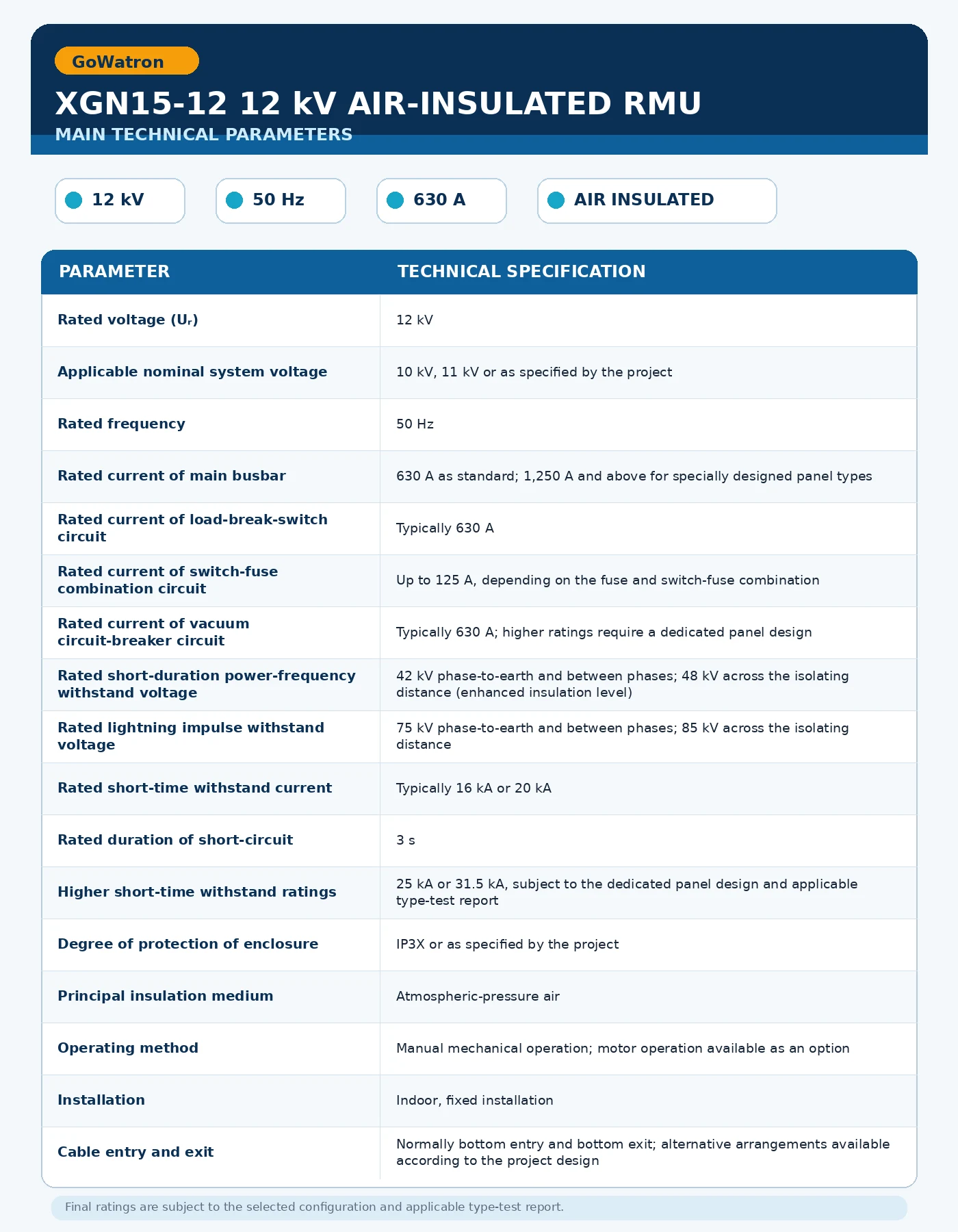
- The following values are typical. Final ratings shall be confirmed according to the specific panel type, switching devices, project technical agreement and applicable type-test reports.
4.1 Rated Voltage
- The rated voltage of the switchgear is 12 kV, while 11 kV is normally the nominal voltage of the distribution system. The recommended description is therefore:
- Rated voltage: 12 kV; suitable for 11 kV medium-voltage distribution systems.
- It should not be described as “11 kV rated voltage/12 kV maximum operating voltage.”
4.2 Insulation Level
- This product is designed and tested with an enhanced rated short-duration power-frequency withstand voltage of 42/48 kV. This exceeds the conventional IEC 62271‑1 insulation level of 28/32 kV for 12 kV equipment.
- The 42/48 kV rating applies only to panel types and configurations that have passed the corresponding dielectric type tests. It shall not be applied to other configurations that have not undergone equivalent test verification.
- The published technical data, project technical agreement, nameplate ratings and type-test reports shall be consistent.
- Under IEC 62271‑1, the conventional rated short-duration power-frequency withstand voltage for 24 kV equipment is generally 50/60 kV. The 42/48 kV rating shall therefore not be described as the conventional IEC insulation level for 24 kV equipment.
4.3 Rated Current
- The conventional rated current of an XGN15‑12 load-break-switch panel is generally 630 A. Ratings of 1,250 A, 1,600 A or 2,000 A shall not be presented as standard ratings applicable to every XGN15‑12 panel.
- Where a rated current of 1,250 A or above is required, a specially designed and type-tested circuit-breaker panel shall be used. The following characteristics shall be verified:
- Main-busbar current-carrying capability
- Temperature rise of contacts and connections
- Heat dissipation within the enclosure
- Short-time withstand current
- Peak withstand current
- Internal arc performance
- Applicable type-test results
4.4 Short-Circuit Capability
- A rated short-time withstand current of 16 kA or 20 kA may be offered as a conventional rating. Ratings of 25 kA or 31.5 kA shall be confirmed against the specific enclosure design and applicable type-test report and shall not be treated as standard ratings for every panel type.
- The rated short-time withstand current of a load-break switch shall not be confused with short-circuit breaking current. Short-circuit faults shall be interrupted by a vacuum circuit-breaker, a switch-fuse combination or an upstream protective device within its applicable rated capability.
5. Normal Service Conditions
The normal service conditions are as follows:
- Installation location: indoors;
- Ambient air temperature: −15°C to +45°C;
- Installation altitude: not exceeding 1,000 m above sea level;
- The surrounding air shall be free from excessive dust, smoke, corrosive gases, flammable gases, salt contamination and conductive pollution;
- The installation location shall not be subject to severe vibration or impact beyond the equipment design limits;
- Appropriate ventilation, moisture-control and anti-condensation measures shall be provided.
- An ambient temperature of +45°C exceeds the conventional maximum ambient temperature of +40°C specified in IEC 62271‑1 and therefore constitutes a special service condition.
- For operation above +40°C, the rated current, permissible temperature rise, enclosure heat dissipation and thermal performance of insulating materials shall be verified by design assessment and applicable testing.
- Where the equipment is installed at an altitude above 1,000 m or under conditions involving high temperature, high humidity, severe condensation, heavy pollution, salt-laden air, sand or seismic activity, the external insulation, electrical clearances, creepage distances, temperature rise, current-carrying capability, corrosion protection and structural strength shall be specifically evaluated.
- Suitability for markets in Southeast Asia, Africa, the Middle East, South America or other regions cannot be determined solely from the voltage rating. The local power frequency, maximum ambient temperature, altitude, humidity, pollution severity, salt-mist exposure, seismic requirements and utility specifications shall also be reviewed.
- Detailed site conditions should be provided to the manufacturer during the early project stage to support product selection, engineering verification and final rating confirmation.
Product Advantages
6.1 High Operational Safety
- The XGN15‑12 incorporates comprehensive mechanical or electrical interlocking among the main switching device, disconnector, earthing switch and compartment doors.
- This reduces the risk of closing an earthing switch onto an energised circuit, energising a circuit while the earthing switch is closed or accessing an energised compartment.
- The segregated construction helps limit the effects of an internal fault. Any claimed internal arc capability and classification shall be supported by the applicable IAC classification and type-test report.
6.2 Air Insulation and Convenient Maintenance
- Atmospheric-pressure air is used as the principal insulation medium, so the air-insulated main circuit does not require periodic gas replenishment.
- When a completely SF₆-free switching configuration is selected, the need for SF₆ pressure monitoring, leakage inspection and gas-recovery management is also eliminated, supporting environmentally responsible medium-voltage distribution.
- Although the air-insulated main circuit does not require gas replenishment, the enclosure, insulating components and switching mechanisms shall still be inspected periodically in accordance with the manufacturer’s maintenance manual.
6.3 Compact and Flexible Installation
- Compared with conventional large metal-clad switchgear, the XGN15‑12 features a compact enclosure, relatively small footprint and flexible arrangement, making it suitable for indoor substations and prefabricated substations.
- Compared with fully insulated gas-insulated ring main units of equivalent ratings, the XGN15‑12 is generally slightly larger. However, it remains a compact design within the category of fixed air-insulated switchgear.
6.4 Flexible Configurations
- Depending on the circuit duty and protection requirements, the switchgear can be configured with a load-break switch, switch-fuse combination or vacuum circuit-breaker. It is suitable for ring-main feeders, terminal feeders and distribution-transformer circuits.
6.5 Competitive Overall Cost
- The air-insulated construction is straightforward and facilitates inspection, maintenance and fault diagnosis. When the project requirements are satisfied, the product generally provides competitive procurement costs, convenient spare-parts availability and straightforward maintenance.
- The actual cost depends on the switching device, rated current, short-circuit rating, condition-monitoring functions, internal arc classification and applicable project standards.
6.6 Intelligent Upgrade Capability
- Motor-operated mechanisms, numerical protection, temperature monitoring, partial-discharge monitoring, communication gateways and remote-control equipment can be added to provide condition monitoring, fault warning and remote distribution management.
7. Applications
- Overseas municipal power distribution. Suitable for 10 kV, 11 kV and 12 kV medium-voltage ring-main and terminal distribution systems, including new construction, network expansion and ring-network upgrading projects. The local power frequency, highest system voltage, short-circuit level and utility requirements shall be confirmed during equipment selection.
- Industrial and commercial distribution. Suitable for medium-voltage incoming and outgoing feeders, ring-main distribution and distribution-transformer control and protection in factories, industrial parks, commercial complexes, hotels, office buildings and data centres.
- Prefabricated substations. Suitable as the high-voltage switching, isolation and protection unit of European-type prefabricated substations, with load-break-switch, switch-fuse combination or vacuum circuit-breaker configurations. For pad-mounted or American-type substations, suitability shall be confirmed according to the high-voltage construction, connection method and applicable local standards.
- Public buildings and community infrastructure. Suitable for medium-voltage terminal distribution systems in residential developments, schools, hospitals, airports, railway stations and other public facilities, providing switching, isolation and protection for medium-voltage feeders and distribution transformers.
- Infrastructure and renewable-energy projects. Suitable for 12 kV indoor medium-voltage distribution systems in rail-transit auxiliary facilities, photovoltaic power plants, wind farms, battery energy storage systems, water-treatment facilities, mines and other infrastructure projects.
- Existing distribution-system refurbishment. Suitable for equipment replacement and upgrading in existing substations, residential developments and industrial facilities. Before refurbishment, the enclosure dimensions, busbar interfaces, cable specifications, system short-circuit level, earthing arrangement and upstream/downstream protection coordination shall be verified.


