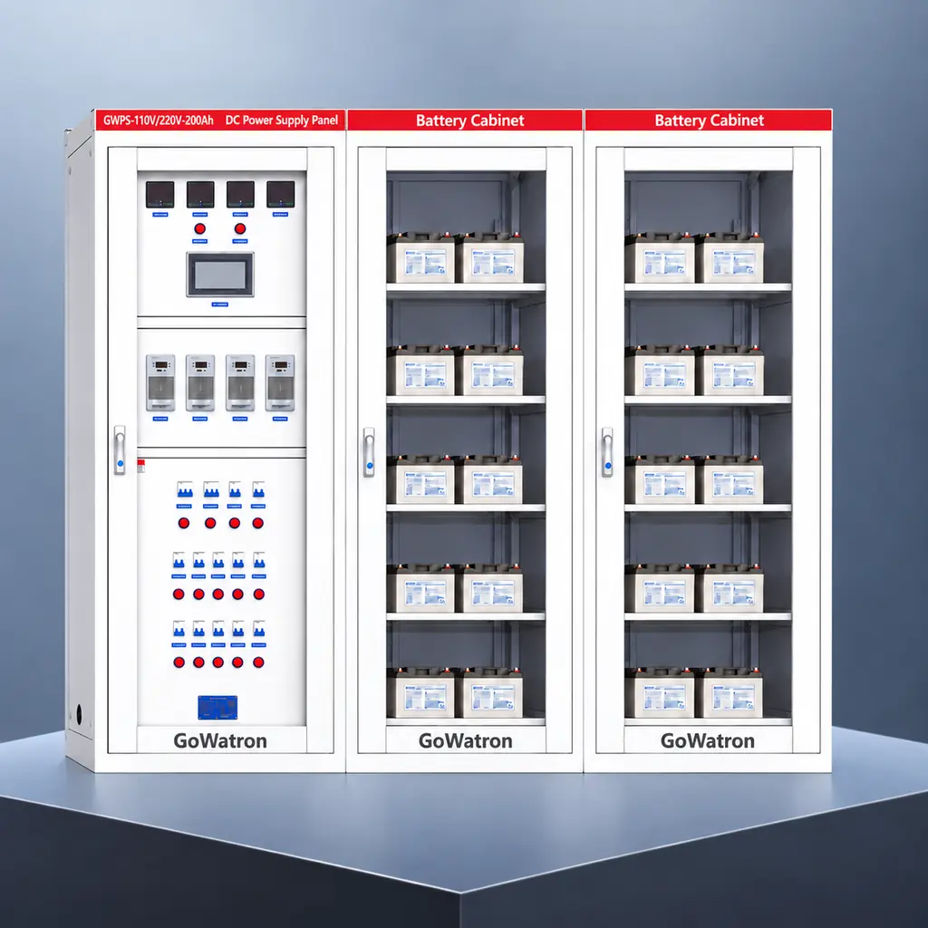
GWPS-110V/220V-200Ah DC Power Supply System/Panel
- The GoWatron GWPS-110V/220V-200Ah is an integrated station DC power supply system designed for substations, power plants, renewable energy facilities and industrial power distribution projects. Its typical rated DC voltage is 110 V DC or 220 V DC, with a 200 Ah battery bank.
- The system provides a stable and reliable DC supply for protection relays, bay control units, circuit-breaker trip and close circuits, signalling systems, communication equipment and emergency lighting.
- Under normal operating conditions, the high-frequency switch-mode charger modules supply the connected DC loads while charging the battery bank. If the AC auxiliary supply fails, the battery bank immediately supplies the essential DC loads, ensuring the uninterrupted operation of protection, control, signalling, communication and circuit-breaker operating circuits.
- The system provides intelligent monitoring, automatic battery charging, DC insulation monitoring, fault alarms and remote communication. In addition to 110 V DC and 220 V DC, GoWatron can provide systems rated at 24 V DC, 48 V DC and 125 V DC, as well as other customised voltage levels.
- The battery capacity, charger module ratings, outgoing feeder configuration, DC busbar arrangement and panel construction can all be customised to meet specific project requirements.





1. Product Introduction
- The GWPS-110V/220V-200Ah DC Power Supply System mainly comprises an AC distribution unit, high-frequency switch-mode charger modules, a DC distribution unit, a 200 Ah battery bank, an intelligent monitoring unit and a DC insulation monitoring device.
- The system features a modular design. The charger modules support parallel operation and automatic current sharing and may be configured with N+1 redundancy according to the continuous load and battery-charging requirements.
- If a charger module becomes faulty, the faulty module is isolated automatically while the remaining modules continue to supply the connected DC loads. This arrangement improves the availability and reliability of the station DC power supply system.
- The system may be equipped with one or two AC incoming supplies and configured with a single DC busbar, a sectionalised single DC busbar or a project-specific busbar arrangement. It can therefore accommodate different national practices, rated DC voltages and project requirements.
Main Technical Parameters
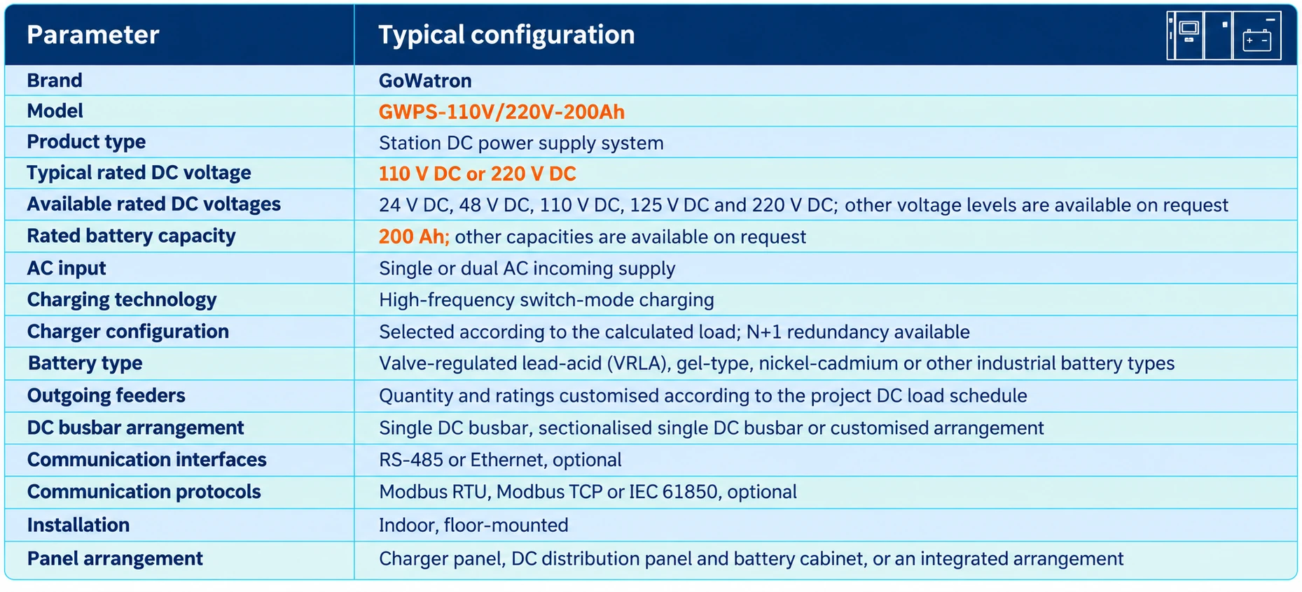
Model designation: GWPS-110V/220V-200Ah represents a typical system with a rated voltage of either 110 V DC or 220 V DC and a 200 Ah battery bank. The rated DC voltage, battery capacity and system configuration can be customised to meet the project specification.
2. System Configuration
2.1 AC Distribution Unit
- The AC distribution unit supplies power to the high-frequency switch-mode charger modules. The system may be equipped with either one or two AC incoming supplies.
- Where two independent AC supplies are provided, an automatic or manual transfer arrangement can be included to improve AC supply reliability.
The AC distribution unit typically includes:
- AC incoming circuit breakers;
- An automatic/manual transfer switch for dual AC supplies;
- AC voltage and current measurement;
- Surge protection devices;
- AC overvoltage, undervoltage and phase-loss monitoring;
- AC incoming supply failure alarms.
2.2 High-Frequency Switch-Mode Charger Modules
The high-frequency switch-mode charger modules convert the incoming AC supply into a stable, regulated DC output. They supply the continuous DC loads while charging the battery bank.
Principal features include:
- Modular parallel operation;
- Automatic current sharing;
- Constant-voltage and constant-current control;
- Float charging, boost charging and current-limited charging;
- N+1 redundant configuration;
- Input and output protection;
- Automatic isolation of a faulty module.
The rating and quantity of the charger modules are selected according to the continuous DC load, required battery-charging current and redundancy criteria.
2.3 200 Ah Battery Bank
- The typical system configuration includes a 200 Ah battery bank.
- Under normal operating conditions, the battery bank is maintained on float charge or boost charge as required. If the AC auxiliary supply fails or the charger becomes unavailable, the battery bank immediately supplies the connected DC load, including protection, control, signalling, communication and circuit-breaker operating circuits.
- The number of battery cells or blocks depends on the rated DC voltage and the nominal voltage of each cell or block. Battery type and capacity can be selected according to the required battery autonomy, load characteristics, ambient conditions and project specification.
2.4 DC Distribution Unit
The DC distribution unit supplies the connected loads through individual outgoing feeders and provides feeder protection and fault isolation.
Typical outgoing feeders include:
- Protection relay feeders;
- Bay control and automation equipment feeders;
- Circuit-breaker trip circuits;
- Circuit-breaker close circuits;
- Control and signalling circuits;
- Communication equipment feeders;
- Emergency lighting feeders;
- Uninterruptible power supply (UPS) or inverter input feeders.
The quantity of outgoing feeders, circuit-breaker ratings and feeder designations can be customised according to the project DC load schedule.
2.5 Intelligent Monitoring and DC Insulation Monitoring
The intelligent monitoring unit provides centralised supervision of:
- AC input voltage and supply status;
- DC busbar voltage and continuous load current;
- Charger module operating status;
- Battery-bank voltage and charge/discharge current;
- Outgoing feeder circuit-breaker status;
- DC busbar insulation condition;
- System faults, alarms and event records.
The DC insulation monitoring device continuously monitors the insulation resistance of the positive and negative DC busbars to earth.
If insulation deterioration or a DC earth fault occurs, the system generates an alarm. An optional earth-fault feeder detection function can help identify the affected outgoing feeder.
3. Load Capacity
- The GWPS-110V/220V-200Ah DC Power Supply System is designed to supply high-voltage and low-voltage switchgear panels, protection panels, control panels, communication panels and other essential DC equipment.
3.1 Number of Switchgear Panels That Can Be Supplied
- For preliminary planning, the continuous DC load of protection relays, bay control units, control circuits, status indication and communication equipment installed in a typical high-voltage switchgear panel may be estimated at approximately 15–40 W per panel.
- Depending on the equipment installed, the required battery autonomy and the circuit-breaker operating duty, one 200 Ah station DC power supply system can typically supply the DC control circuits of approximately 30–100 high-voltage and low-voltage switchgear panels.
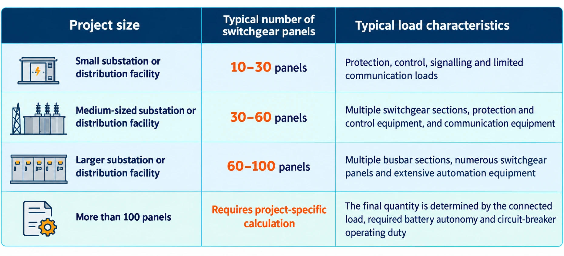
As a general guide:
- Fully equipped high-voltage switchgear: approximately 30–60 panels;
- High-voltage and low-voltage switchgear with mainly control, signalling and monitoring loads: approximately 50–100 panels;
- Mixed installations comprising switchgear panels, protection panels, control panels and communication panels: the final quantity must be determined from the actual DC load schedule.
These quantities are preliminary planning values and do not represent a fixed system limit. The actual number of switchgear panels depends on the continuous DC load of each panel, circuit-breaker trip coil and close coil currents, shared DC loads and the required battery autonom
3.2 Continuous Loads
Continuous loads remain energised during normal system operation and typically include:
- Protection relays;
- Bay control units;
- Supervisory control and data acquisition (SCADA) systems;
- Substation automation equipment;
- Circuit-breaker control circuits;
- Signalling and alarm equipment;
- Communication equipment;
- Switchgear status indication;
- DC system monitoring and insulation monitoring devices.
Assuming an average continuous load of 20 W per switchgear panel:
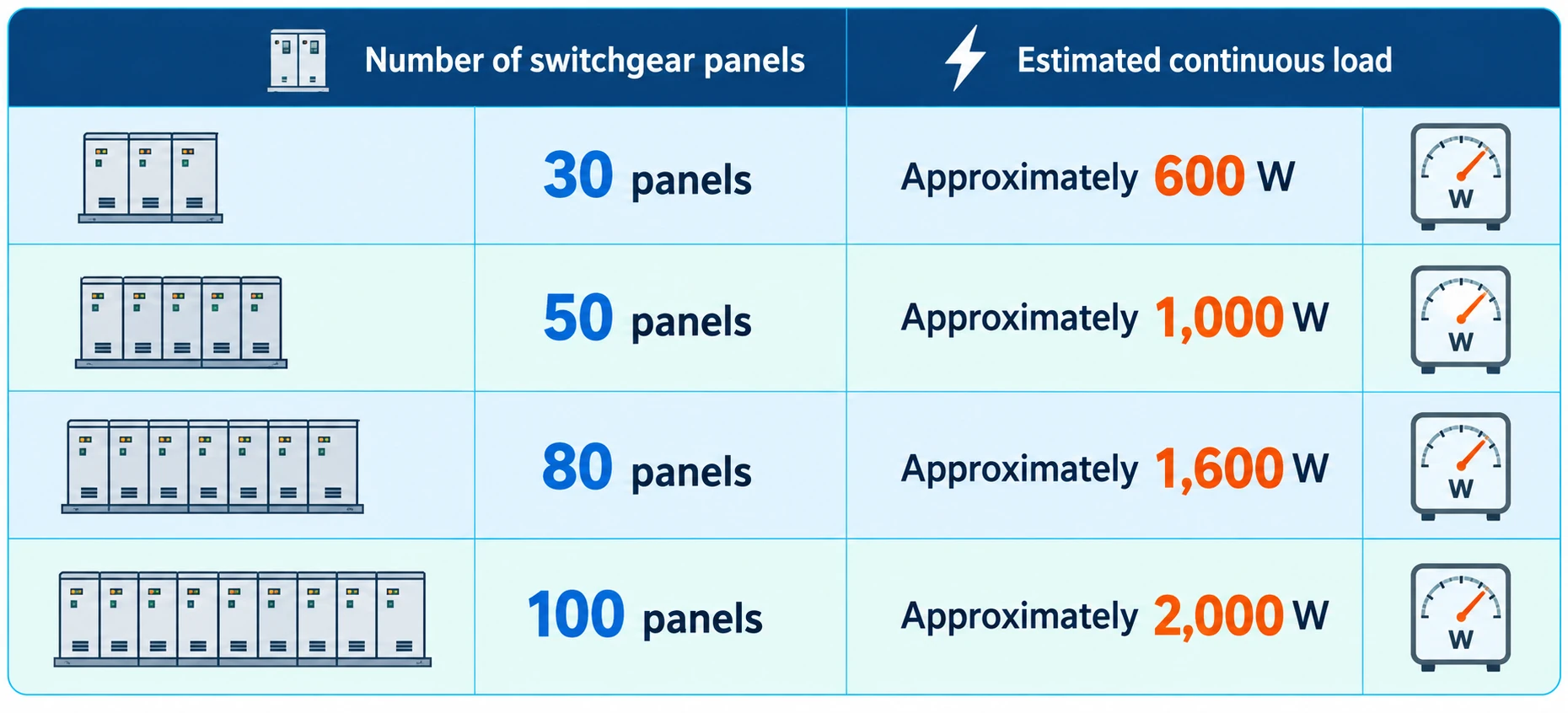
For example, 50 switchgear panels with an average continuous load of 20 W per panel represent a total continuous load of approximately 1,000 W.
The corresponding DC load current is approximately:
- 9.1 A for a 110 V DC system;
- 4.5 A for a 220 V DC system.
The final calculation must also include protection panels, control panels, communication equipment, emergency lighting and other shared DC loads
3.3 Short-Time Loads
Circuit-breaker trip coils, close coils and motor-operated mechanisms are short-time loads. Although their operating periods are brief, their instantaneous current draw may be considerably higher than the continuous load of the protection and control equipment.
The system design must therefore take account of:
- The trip current of an individual circuit breaker;
- The closing current of an individual circuit breaker;
- The maximum number of circuit breakers operating simultaneously;
- The number of circuit breakers required to trip under a fault condition;
- The DC busbar voltage at the end of the battery discharge period;
- Voltage drop across outgoing feeder cables;
- DC circuit-breaker ratings and protection coordination.
3.4 Emergency Loads
If all AC auxiliary supplies are lost, the battery bank continues to supply essential loads such as:
- Protection relays and automatic protection systems;
- Circuit-breaker trip and close circuits;
- Emergency signalling and alarm systems;
- Essential control and communication equipment;
- SCADA and telecontrol equipment;
- Emergency lighting;
- Other equipment required to remain operational during an AC supply failure.
3.5 Load Sizing Considerations
A battery capacity of 200 Ah indicates the nominal capacity of the battery bank. It does not by itself determine a fixed connected load or battery autonomy.
The number of switchgear panels that can be supplied must be determined by considering:
- Rated DC system voltage;
- Continuous load of each switchgear panel;
- Circuit-breaker trip coil and close coil currents;
- Maximum simultaneous circuit-breaker operating duty;
- Protection panel and communication equipment loads;
- Emergency lighting load;
- Required battery autonomy;
- Ambient temperature;
- Battery ageing factor;
- Design margin.
GoWatron can calculate the required battery capacity, charger rating and outgoing feeder configuration based on the project DC load schedule, required battery autonomy and operating conditions.
4. Product Functions
4.1 Continuous DC Power Supply
- When the AC auxiliary supply is available, the charger modules supply the connected DC loads and charge the battery bank.
- If the AC auxiliary supply fails, the battery bank immediately supplies the connected load without interruption, ensuring reliable operation of essential protection, control, signalling and communication equipment.
4.2 Automatic Battery Charging Management
- The system automatically manages float charging, boost charging and current-limited charging. The charging mode is selected according to the battery condition and configured operating criteria, helping to prevent overcharging or prolonged undercharging.
4.3 Redundant Charger Modules
- The charger modules support parallel operation, automatic current sharing and N+1 redundancy. If one charger module becomes faulty, the faulty module is isolated automatically while the remaining modules continue to supply the connected DC loads.
4.4 DC Insulation Monitoring
- The system continuously monitors the insulation resistance of the positive and negative DC busbars to earth. It generates an alarm if insulation deterioration or a DC earth fault is detected.
- An optional earth-fault feeder detection function can identify the affected outgoing feeder.
4.5 Battery Monitoring
- The system monitors battery-bank voltage, charge/discharge current and operating condition.
- An optional battery monitoring unit can also monitor individual cell or battery-block voltages and temperatures, helping operators identify weak or abnormal cells or blocks.
4.6 Outgoing Feeder Protection
- Each outgoing feeder can be provided with an individual DC protective device. If an overload or short circuit occurs on one feeder, the affected feeder can be isolated while the remaining essential loads continue to operate.
4.7 Fault Alarms
The system can monitor and report:
- AC incoming supply failure;
- AC overvoltage, undervoltage or phase loss;
- DC busbar overvoltage or undervoltage;
- Charger module failure;
- Abnormal battery voltage;
- DC insulation deterioration or earth fault;
- Outgoing feeder circuit-breaker trip;
- Equipment overtemperature;
- Communication failure.
4.8 Remote Communication
- Through RS-485 or Ethernet interfaces, the system can transmit measurements, equipment status and alarm information to a substation automation system, SCADA system or energy management system.
- Communication protocols can be configured according to project requirements, including Modbus RTU, Modbus TCP and IEC 61850.
5. Applications
- Substations: Supplies protection relays, bay control units, signalling systems, communication equipment and circuit-breaker trip and close circuits in substations at different voltage levels.
- Power plants: Supplies protection, control, signalling, communication and emergency loads in thermal, hydroelectric, gas-fired and other power generation facilities.
- Solar power plants: Supplies protection, automation, communication and high-voltage switchgear control circuits in solar substations and switching stations.
- Wind farms: Supplies protection relays, bay control units, communication systems, signalling circuits and circuit-breaker operating mechanisms in wind-farm substations.
- Battery energy storage systems (BESS): Supplies protection, control, monitoring, communication and emergency operating circuits in energy storage substations, power conversion systems and grid-connection facilities.
- Industrial substations: Supplies protection, control, signalling and switchgear operating circuits in mining, metallurgical, steel, petrochemical, cement and manufacturing facilities.
- Rail transport systems: Supplies protection, monitoring, communication, signalling and circuit-breaker operating circuits in railway, metro and urban rail traction and distribution substations.
- Data centres: Supplies protection, control, monitoring, communication and emergency operating equipment within data-centre electrical distribution systems.
- Airports and ports: Supplies protection, automation, communication and switchgear control circuits in airport, port and logistics-hub electrical distribution facilities.
- Water and municipal infrastructure: Supplies protection, control, signalling and emergency equipment in water-treatment plants, wastewater-treatment facilities, pumping stations and other municipal electrical installations.


