GWPS-DCW-110/220V 24AH Wall-Mounted DC Power Supply System
Product Desc
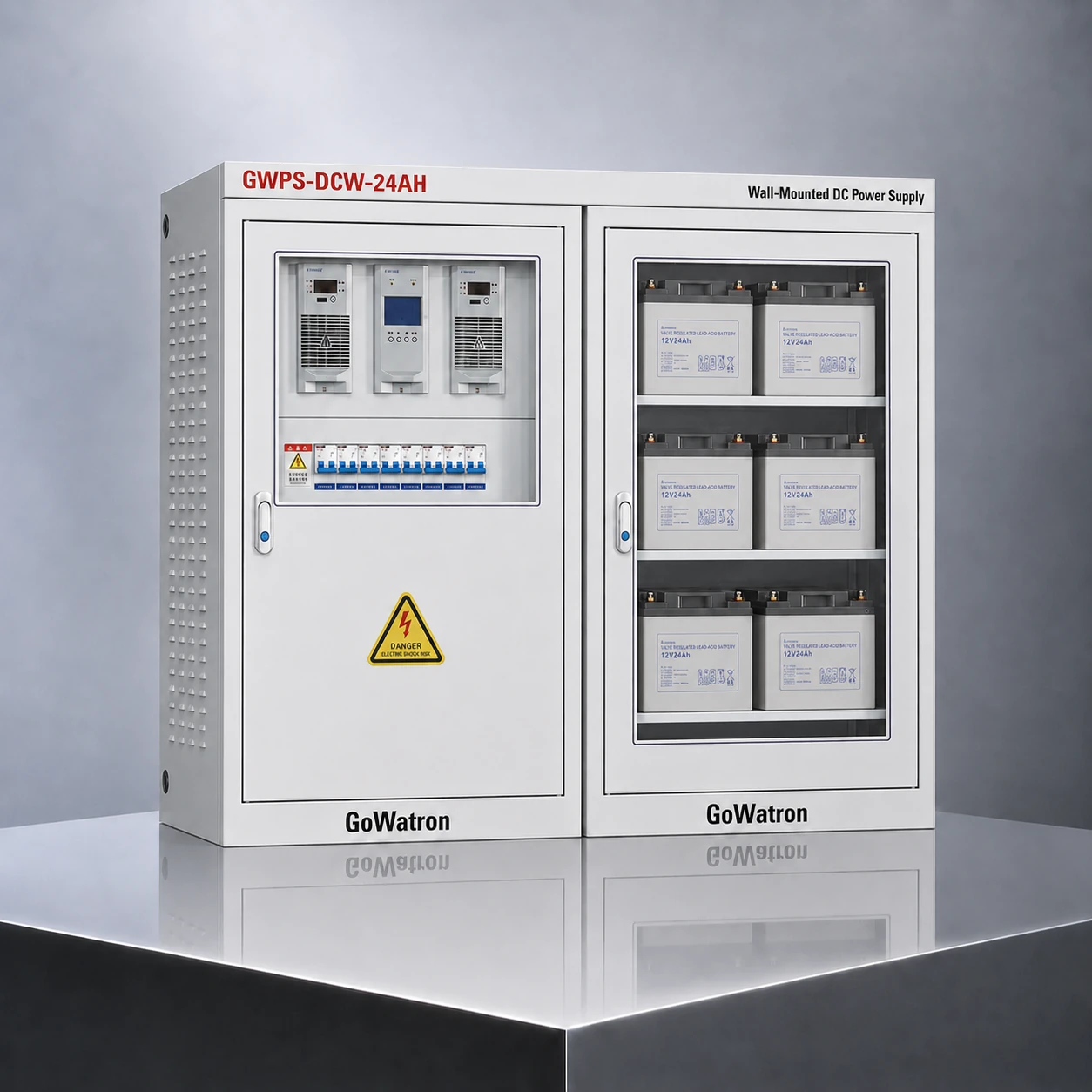
- The GWPS-DCW-110/220V 24AH Wall-Mounted DC Power Supply System is an integrated DC auxiliary power system developed by GoWatron for small switching stations, customer substations, distribution rooms and other applications with relatively low DC loads.
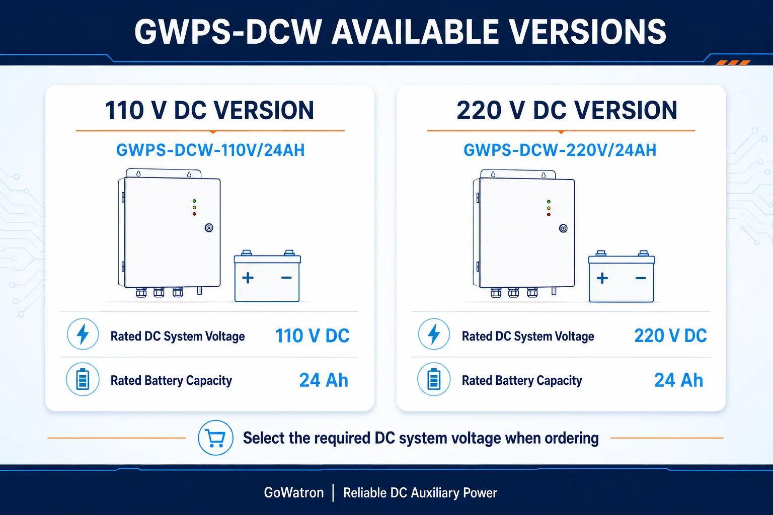
- Available in 110 V DC or 220 V DC versions, the system is equipped with a 24 Ah battery bank. It integrates AC input distribution, rectification and charging, battery management, silicon-diode voltage reduction, DC distribution, insulation monitoring, alarm annunciation and communication management.
- The system provides a stable and reliable DC supply for protection relays, bay control units, automation equipment, circuit-breaker opening and closing circuits, control circuits and signalling equipment.





Dual Voltage Options
110 V DC or 220 V DC

Battery Backup
24 Ah Battery Bank

Smart Charging
Float & Boost Charging

Insulation Monitoring
DC Earth-Fault Alarm

Compact Installation
Wall-Mounted Design

Fast Delivery
Global Shipping

Warranty
2 Year Warranty
Product Introduction
- The GWPS-DCW-110/220V 24AH Wall-Mounted DC Power Supply System is designed for power applications with relatively low DC loads, a limited number of outgoing feeders or restricted installation space.
- The system consists of an AC input unit, high-frequency switch-mode rectifier modules, a system monitoring unit, a silicon-diode voltage-dropping unit, a DC distribution unit, an insulation monitoring unit, a 24 Ah battery bank and a wall-mounted enclosure. These components form a complete, self-contained DC auxiliary power system.
- Under normal AC supply conditions, the rectifier modules convert the AC input into a regulated DC output. The rectifiers simultaneously supply the connected DC loads and charge the battery bank according to the configured charging mode. If the AC supply fails, the battery bank supplies the DC bus directly, maintaining power to protection, control, signalling and circuit-breaker opening and closing circuits.
- The monitoring unit continuously supervises the AC inputs, rectifier modules, DC buses, battery bank and outgoing feeders. It also manages battery float and boost charging according to preset operating thresholds. Alarms can be generated for AC supply failure, rectifier module failure, abnormal DC bus voltage, battery abnormalities, low insulation resistance and DC earth faults.
Key features
- Available in 110 V DC and 220 V DC versions;
- 24 Ah rated battery capacity;
- Integrated charging, energy storage, monitoring and DC distribution;
- Battery-backed operation following loss of the AC supply;
- Automatic battery charging and management;
- LCD-based monitoring and menu operation;
- DC insulation monitoring and comprehensive alarm functions;
- Compact wall-mounted construction;
- Modular design for convenient installation and maintenance.
System Components and Configuration
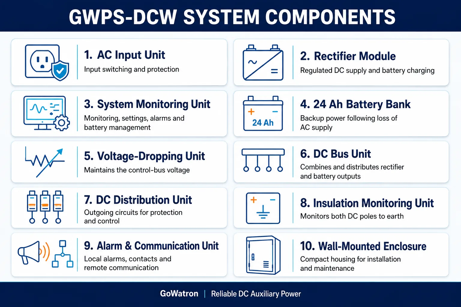
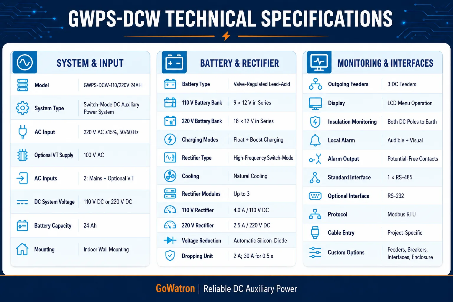
- Typical configuration: Two AC inputs are provided: one mains supply input and one optional VT (PT) supply input. The system can accommodate up to three naturally cooled high-frequency switch-mode rectifier modules, subject to the system load and thermal design. The 220 V DC version may use 2.5 A/220 V rectifier modules, while the 110 V DC version may use 4.0 A/110 V rectifier modules. The system includes a 24 Ah valve-regulated lead-acid battery bank, an automatic silicon-diode voltage-dropping unit, an LCD monitoring unit and DC insulation monitoring. Three DC outgoing feeders are provided as standard. The number of feeders, protective-device ratings and communication options can be adapted to project requirements.
Functions
- Reliable DC auxiliary supply: Provides a stable DC supply for protection relays, bay control units, automation equipment, circuit-breaker operating mechanisms, control circuits and signalling circuits.
- Battery-backed supply following AC failure: If the AC input fails, the 24 Ah battery bank supplies the DC bus directly, maintaining the operation of protection, control, signalling and circuit-breaker opening and closing circuits.
- Automatic charging management: Supports float charging, boost charging and charge-current limiting, with automatic transition between float and boost charging based on preset thresholds.
- System condition monitoring: Continuously monitors the AC input voltage, rectifier module status, battery-bank voltage, battery charge/discharge current, closing-bus voltage, control-bus voltage, control-bus current, outgoing feeder status and DC bus insulation condition.
- Automatic battery management: Monitors battery voltage and charge/discharge current, manages the charging cycle and detects and reports battery overvoltage, undervoltage and abnormal operating conditions.
- Automatic voltage reduction: Uses a silicon-diode voltage-dropping unit to regulate the control-bus voltage, preventing the elevated bus voltage during boost charging from being applied directly to protection, control and signalling equipment.
- DC insulation monitoring: Continuously monitors the insulation resistance of the positive and negative DC poles to earth. An alarm is generated if the insulation resistance falls below the preset threshold or a DC earth fault occurs.
- Outgoing feeder protection and fault isolation: Each outgoing DC feeder can be equipped with an independent DC circuit breaker, providing individual circuit switching, overcurrent protection and fault isolation. This reduces the effect of a feeder fault on other DC loads.
- Rectifier module protection: Provides output current limiting, overcurrent protection, overvoltage protection, short-circuit protection and overtemperature protection. When multiple rectifier modules operate in parallel, a faulty module can be disconnected while the remaining healthy modules continue operating.
- Alarm annunciation: Collects and reports system alarms, including AC input failure, rectifier module failure, abnormal DC bus voltage, battery abnormalities, outgoing feeder faults, low insulation resistance and DC earth faults.
- Communication and remote monitoring: One RS-485 interface with Modbus RTU is provided as standard. An RS-232 interface and other communication protocols are available according to project requirements. Measurements, operating status and alarm information can be transmitted to a substation automation system or SCADA system.
Technical Specifications
Available Versions
Backup Duration
- The 24 Ah value is the rated capacity of the battery bank. Actual backup duration depends on the continuous DC load, end-of-discharge voltage, discharge rate, ambient temperature, battery ageing and the required design margin. A fixed five-hour backup duration therefore cannot be guaranteed for every application.
- Estimated backup duration (h) = available battery capacity (Ah) ÷ average continuous load current (A)
- For preliminary engineering estimates, the available battery capacity may be taken as approximately 70%–80% of the rated capacity to allow for ageing and design margin. Final battery sizing shall be based on the battery manufacturer’s discharge curves, end-of-discharge voltage, discharge rate, ambient temperature, required service life and applicable project requirements.
- For purely DC loads, an inverter-efficiency factor is not applicable. Cable voltage drop, protective-device voltage drop and other DC circuit losses should be considered where relevant.
- Load capability: Under defined load conditions, the system may supply the protection, control and operating circuits associated with approximately three to five medium-voltage switchgear panels. The actual number of panels and backup duration must be confirmed by a DC load assessment covering continuous loads, emergency loads and the momentary current required for circuit-breaker opening and closing operations.
Applications
- Small switching stations and distribution substations: Supplies DC power to protection relays, bay control units, control circuits, signalling circuits and circuit-breaker operating mechanisms.
- Small customer substations: Suitable for small power distribution systems with relatively low DC loads and a limited number of outgoing feeders.
- Distribution substations rated up to 10 kV: Provides DC auxiliary power for protection, measurement, control and signalling equipment installed in medium-voltage switchgear.
- Compact substations: Its space-saving wall-mounted construction makes the system suitable for compact substations and other installations with restricted equipment space.
- Ring main units and switchgear assemblies: Supplies protection devices, motor-operated mechanisms, communication equipment and control circuits.
- Commercial and industrial distribution rooms: Provides DC power for circuit-breaker operation, protection, control, signalling and distribution automation equipment.
- Renewable-energy power systems: Suitable for auxiliary DC supply applications in PV power stations, wind farms and battery energy storage facilities.
- Industrial and municipal facilities: Applicable to industrial plants, pumping stations, water-treatment facilities and other sites requiring a reliable DC auxiliary power supply.
The rated DC voltage, feeder configuration, rectifier capacity and required backup duration should be selected according to the project’s DC load assessment and technical requirements. For projects requiring a larger battery capacity or longer backup duration, please refer to the GWPS-DC series product family for alternative configurations.


