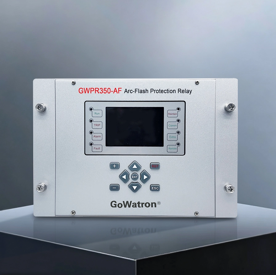
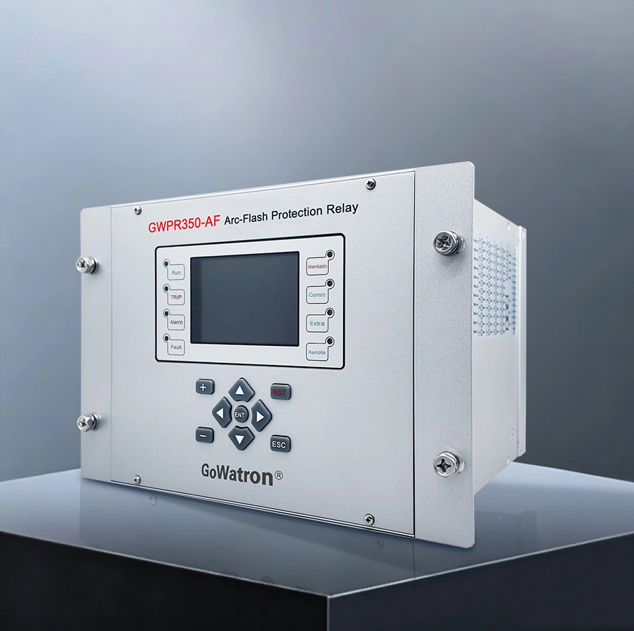
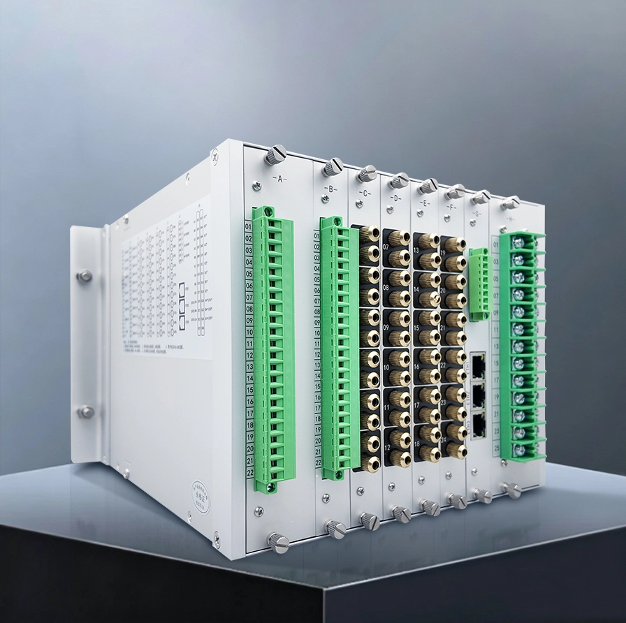
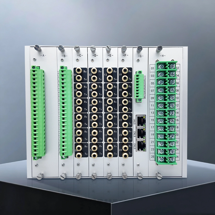


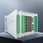
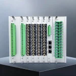
GWPR350-AF Busbar Arc-Flash Protection Relay
Developed for 0.4 kV to 132 kV power distribution systems, the GWPR350-AF Busbar Arc-Flash Protection Relay provides ultra-fast fault protection. It is engineered to detect and clear arc-flash faults within milliseconds to reduce equipment damage, prevent personnel injuries and limit power outages, acting as a vital safeguard to secure system reliability. Equipped with integrated protection, monitoring, control, communication and event recording functions, the relay realizes reliable busbar arc-flash protection and automatic control for distribution networks. It supports multiple protection modes: pure arc tripping, dual-criterion tripping, overcurrent alarming, arc-flash alarming and time-delay protection. Widely applicable to busbar protection, feeder protection and single-cabinet protection, it fully meets varied protection demands of medium and low-voltage power distribution systems.
- Modbus-TCP, Modbus-RTU; 2 RS485 serial communication interfaces
- IEC 60870-5-104 protocol; 3 optional Ethernet ports
- IEC 61850 (optional) and other communication protocols are supported




Product Features
Protection Functions
- (ANSI 50AF) Arc-Flash Single-Criterion Trip
- (ANSI 50AF/50) Arc-Flash & Current Dual-Criterion Trip
- (ANSI 50AF/59N) Arc-Flash & Zero-Sequence Voltage Dual-Criterion Trip
- (ANSI 50AF/50/59N) Arc-Flash + Current + Zero-Sequence Voltage Triple-Criterion Trip
- (ANSI 50AF) Time-Delayed Arc-Flash Protection
- (ANSI 50BF)Circuit Breaker Failure Protection
- (ANSI 86/94) Interlocking Protection
- (ANSI 50AF) Arc-Flash Alarm
- (ANSI 59N) Zero-Sequence Overvoltage Alarm
I. Four Core Arc Flash Trip Protection Logics (Core Fault Clearing Function)
The device supports multiple protection logics including single-criterion, dual-criteria and triple-criteria arc flash protection, adapting to various power distribution scenarios while balancing operating speed and anti-maloperation capability. It can clear arc faults rapidly within ≤8 ms at the fastest speed.
(ANSI 59AF) Arc-Only Tripping
Tripping is triggered solely when the light intensity detected by arc flash sensors exceeds the operating threshold, without auxiliary current or voltage criteria.
- Operating speed: ≤8 ms, the fastest protection logic across the full product range;
- Applicable scenarios: Independent enclosed switchgear compartments, compact busbar compartments and cable compartments free from sunlight or artificial light interference;
- Advantages: Instantaneous breaker tripping upon fault occurrence, minimizing risks of arc burns and cabinet explosion.
(ANSI 59AF+51) Arc Flash + Overcurrent Dual-Criterion Tripping
Tripping is executed only when two conditions are satisfied simultaneously: ① Arc flash is detected; ② Circuit fault current exceeds the setpoint.
- Operating speed: ≤12 ms;
- Core function: Filters out stray external light interference such as ambient lighting, sunlight and flashlight illumination to prevent protection maloperation;
- Applicable scenarios: Incoming/outgoing feeder cabinets, open-type power distribution rooms and distribution areas vulnerable to external light interference.
(ANSI 59AF+59N) Arc Flash + Residual Voltage Dual-Criterion Tripping
Tripping is triggered when two conditions are met simultaneously: arc flash signal and residual voltage over-limit.
- Targeted faults: Arc faults caused by internal single-phase earth faults in switchgears;
- Applicable scenarios: Non-solidly earthed systems (e.g., unearthed or resonant-grounded systems), PT cabinets and power distribution systems with high risk of busbar earth faults;
- Advantages: Effectively targets single-phase earth arc faults in switchgears, achieving accurate fault judgment and avoiding unnecessary tripping for normal system voltage fluctuation.
(ANSI 59AF+51+59N) Arc Flash + Overcurrent + Residual Voltage Triple-Criterion Tripping
Tripping is executed only when arc flash, fault current and residual voltage all exceed their respective setpoints simultaneously, with triple interlocking.
- Advantages: Extremely low maloperation probability and maximum safety redundancy;
- Applicable scenarios: Class-I critical power supply facilities where unintended outages are prohibited, such as hospitals, data centers and precision chemical plants.
II. Backup Protection Functions (Prevent Fault Propagation)
(ANSI 50BF) Circuit Breaker Failure Time-Delay Protection
Serving as the backup function for arc flash protection, it addresses breaker failure issues including mechanical jamming and trip coil inoperability.
- Operating logic: After the arc flash protection trip command is issued, the device continuously monitors circuit current. If the current remains above the setpoint upon expiry of the adjustable time delay (0–1000 s adjustable), the upstream trip output will be activated automatically;
- Value: When the fault cannot be cleared locally within the cabinet, the upstream power switch is tripped to prevent sustained arcing from burning down the entire busbar section.
(ANSI 85) Interlocking Protection – Graded Coordination Mode
Enables coordinated protection between multiple arc flash protection devices at different levels to establish a station-wide graded busbar protection network.
- Operating logic: When an arc fault occurs in a single cabinet, the device trips the local circuit breaker preferentially and sends an interlocking signal to the host/upstream protection device. Upon receiving the interlock signal, the upstream device conducts a secondary judgment based on its own criteria and trips the main incoming switch if the fault persists;
- Core advantages: Implements fault clearing at the closest source to the fault to minimize outage scope; reduces total on-site fiber optic cabling volume and construction costs; forms a progressive backup protection system that significantly improves power supply reliability.
III. Pre-Warning & Alarm Functions (Pre-fault Hidden Hazard Detection, Non-Tripping)
(ANSI 59AF) Arc Flash Alarm Function
Different from tripping protection, this function generates alarms without tripping and captures incipient weak arc discharge signatures.
- Logic: An alarm signal is triggered when sensors detect faint arc flash whose intensity reaches the alarm threshold;
- Applicable scenarios: Early-stage faults including busbar insulation degradation, loose contact arcing and minor cable discharge;
- Function: Pushes alarm signals to the monitoring background in advance for maintenance personnel to conduct troubleshooting before faults escalate into severe short-circuit arc explosions.
Multi-type Electrical Abnormality Alarms
(ANSI 59N) Residual Overvoltage Alarm
- Continuously monitors system residual voltage. An alarm is output after the overvoltage duration exceeds the adjustable delay (0–1000 s adjustable). It provides early warning of single-phase earth faults, PT fuse failures and busbar insulation deterioration risks.
(ANSI 51) Three-Phase Overcurrent Alarm
- Three groups of sampled currents support independent enabling/disabling of overcurrent alarms with individual current setpoints and adjustable delays (0–1000 s adjustable). Applicable for early warning of overload conditions and incipient short-circuit faults.
IV. Full-Link Self-Test Functions (Ensure Constant Protection Availability)
Device & Optical Path Self-Test (No direct ANSI device number assigned)
Dual self-test covering the entire unit and sensor optical paths continuously monitors equipment health status to fundamentally prevent protection failure to operate.
- Real-time detection of fiber breakage, probe damage and optical attenuation for up to 24 arc flash sensors;
- Automatic identification of faults in device power supply, sampling circuits, trip output contacts and communication channels;
- The front-panel FAULT indicator illuminates upon self-test abnormality, with alarm signals uploaded to the monitoring background simultaneously;
- Compatible with ST self-test-capable sensors supporting bidirectional optical path self-test, completely preventing protection failure caused by fiber breakage.
V. Flexible Setting & Group Management Functions
4 Independent Setting Groups
- Equipped with 4 independent setting groups (Setting Group 1 to Setting Group 4), corresponding to 3 sets of three-phase current sampling loops and 3 residual voltage sampling loops. Protection logics for incoming feeders, bus couplers and outgoing feeders can be configured independently without mutual interference.
Free Association Between Trip Outputs and Arc Flash Channels
- 12 passive trip outputs can be freely bound to any of the 1–24 arc flash sensors via binary coding. Multiple trip outputs can be actuated by one single arc flash detection point, or multiple arc channels can share one trip output, adapting to complex wiring schemes such as multi-cabinet interlocking and sectionalized busbar protection.
Fully Customizable Parameter Setting
- All operating parameters are configurable: criterion mode, overcurrent setpoint, residual voltage setpoint, breaker failure protection delay, alarm threshold, alarm delay, CT ratio, system frequency (50/60 Hz), etc.
VI. Human-Machine Interface & Operation and Maintenance Management Functions
Local Visualized Operation
- Real-time data displayed on the LCD main screen: three-phase currents, residual voltage, online status of 24 arc flash sensors and system time;
- 8 status indicators (RUN / TRIP / ALARM / FAULT / BLOCK / COMM / EXT / SPARE) for intuitive equipment status observation;
- Complete operation keys: RST (Reset), ENT (Enter), ESC (Escape), value adjustment keys and directional cursor. Full commissioning can be completed without external computers.
Comprehensive Fault Record Management
- Four categories of event reports are stored: trip reports, alarm reports, remote signal change reports and fault oscillography records. Each record precisely stores fault timestamp, fault current and triggered arc flash channel.
- Report management functions: single-category clearing, full clearing and on-site real-time access for post-fault review and analysis.
Output Commissioning Test Function
- An independent [Output Test] menu enables manual individual triggering of 12 trip outputs, action signals, alarm signals and self-test contacts. On-site secondary wiring commissioning and circuit verification require no additional test instruments, significantly improving construction efficiency.
VII. Multi-Protocol Remote Communication & Monitoring Functions
Communication Remote Transmission Function (No direct ANSI device number assigned)
Establishes data connection between local equipment and substation automation background to enable remote online monitoring and remote retrieval of fault data.
- Serial communication: 2 RS485 ports as standard, expandable to maximum 4 ports, Modbus-RTU protocol;
- Ethernet communication: 1 Ethernet port as standard, expandable to maximum 3 ports, supporting Modbus-TCP and IEC 61850 protocols for digital substations;
- Remote capabilities: Background real-time reading of current, voltage and arc flash sensor status; reception of trip/alarm signals; remote query of fault reports.
VIII. Maintenance Safety Blocking Function
(ANSI 86) Maintenance Blocking Function
- Fitted with 2 hardware blocking digital input terminals connected to switchgear maintenance test blocks.
When the maintenance test block is enabled during maintenance, the device automatically blocks arc flash protection for the corresponding zone. This prevents protection false tripping induced by work light irradiation or reflective light from tools, ensuring the safety of maintenance personnel.
Typical Applications:
- Power Industry: GIS switchgear, busbar bridge systems, high and low-voltage switchgear, compact secondary substations.
- Industrial Sector: Power distribution and Motor Control Center (MCC) systems for metallurgical, chemical, mining, and manufacturing facilities.
- New Energy Sector: Power distribution and energy storage system protection for photovoltaic power plants and wind farms.
- Commercial & Public Facilities: Power distribution rooms in office buildings, shopping centers, hospitals, educational institutions, and sports venues.
- Other Infrastructure Sectors: Medium and low voltage distribution systems for water conservancy, transportation, marine vessels, data centers, and municipal industrial parks.


